


 本文深入解析了STM32定时器的同步和通讯特性,介绍了如何利用不同频率、相位和波形脉宽生成波形。详细阐述了主从定时器配置、事件触发方式以及定时器通讯功能的预加载设计,适用于复杂波形的精确控制。
前言:
如何实现复杂的不同频率、相位、波形脉宽的波形就在这个章节:
This application example is split into two parts describing two similar application examples.(两个例子)
Both examples use of the inter-timers synchronization to generate an N-pulse waveform but with a small difference:
• Within the first application example, covered by the part 1 of this section, an N-pulse waveform is generated on the output and the complementary output of TIM1 timer channel 1. At the end of the N-pulse waveform generation, the TIM1 timer channel 1 outputs keep their last (互补)where the channel 1 output is low and its complementary output is high.
• Within the second application example, covered by the part 2 of this section, an Npulse waveform is generated on the output and the complementary output of TIM1 timer channel 1. At the end of the N-pulse waveform generation, the TIM1 timer channel 1 outputs should be both low. This can be achieved by using the commutation feature built-in the STM32 timers. This feature is detailed in the second part of this chapter.
1 Timer synchronization overview(定时器同步方法)
Some of the STM32 timers are linked together internally for inter-timer synchronization or chaining.
一些定时器可以内部级联,达到内部定时器同步和定时器链。
The STM32 timer peripherals featuring the inter-timers synchronization capability have only one synchronization output signal named TRGO (abbreviation for “Trigger Out”).
STM32的定时器分离器器件有内部同步的功能,只有一个同步输出信号。
They also have four synchronization inputs (named ITRx where x ranges from 1 to 4) connected to the other STM32 timers synchronization outputs. The reference manual for any STM32 microcontroller lists the inter-timers connection matrix.
有4个同步的输入,ITRX,连接到定时器同步的输出上。
Note that only the timers featuring the master/slave controller unit support the inter-timer synchronization (with only few exceptions). For example, the TIM2 timer peripheral features a master/slave controller unit and it can be synchronized with other STM32 timer peripherals.
注意,只有标识有master/slave控制单元的定时器,支持内部定时器同步。
The TIM2 can trigger events inside other timers through its synchronization TRGO output signal. In this case the TIM2 timer peripheral is acting as a master timer. TIM2 timer peripheral can also be configured to be triggered by other timer synchronization output signals;
TIM2可以通过TRGO输出信号触发内部其他定时器。这种情况下,TIM2定时器作为主控定时器。TIM2也可以配置为被其他定时器同步触发的方式。
in this case the TIM2 timer peripheral is acting as a slave timer. A timer peripheral can act as a slave timer and as a master timer simultaneously.
在这种情况下,TIM2定时器作为从定时器。一个定时器分离器件可以同时充当从、主定时器。
The TIM11 timer peripheral is an example of timer peripheral that does not feature a master/slave controller unit. It does not feature a synchronization of TRGO output signal, but it is able to act as master timer for some other timer peripherals. This is possible through the usage of the TIM11 timer channel output as synchronization output signal. The TIM11 timer channel output is connected to other timer peripherals synchronization inputs.
定时器11 这是没有master/slave的定时器单元。他没有TRGO的同步输出信号。但是,他具备作为master定时的能力。通过TIM11的使用输出一个同步信号,然后,把这个同步信号连接到其他的定时器的输入上。
1.1 Timer-master configuration(主定时器配置和控制的方式)
When a timer peripheral is configured as a master timer, its corresponding synchronization TRGO output signal may output a synchronization pulse next to any of the timer events listed below.
如果一个定时器配置为主定时器,他的同步TRGO的输出信号,将输出同步到下表中的其他任何一个定时器事件.
笔者案:主从定时器的触发同步模式有很多,事件的方式有很多,下面列出的是几种主要的方式。
Note that the presented list is not exhaustive and only the most common modes are listed. The list of master modes may vary from one microcontroller family to another:(本文举例也许对其他版本的MCU并不详尽)
1.1.1EGR(EVENT GENERATE REGISTER)重置
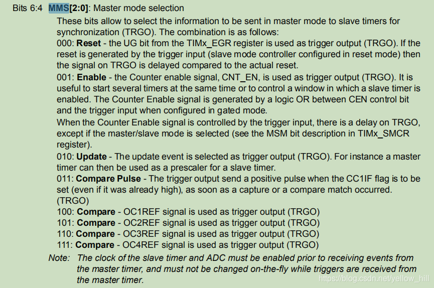
Reset: the UG bit from the EGR register is used as a trigger output (TRGO)
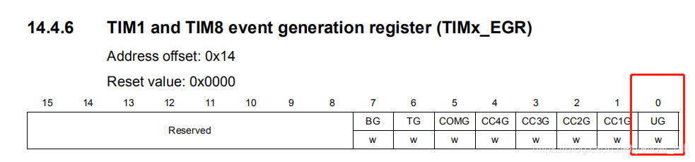
设置UG bit为1 ,
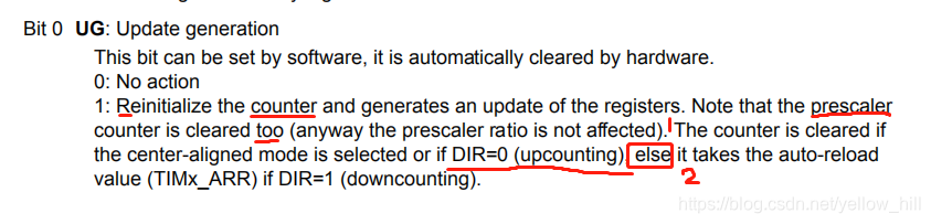
这个设置会把Presscaler重置,同时会分两种情况分别重置Counter的值。
第一种情况,就是主从定时器,通过RESET UG位的方式,重置之前的预设定值。
1.1.2 使能
Enable: the counter enable signal is used as a trigger output (TRGO). It is used to start several timers at the same time, or to control a window in which a slave timer is enabled
Counter 使能信号被用作TRGO。被用于同时启动多个Timer,或者控制一个窗口让从timer使能。
通过控制定时器的使能,
1.1.3 更新
Update: the update event is selected as trigger output (TRGO). For example, a master timer can be used as a prescaler for a slave timer
更新事件作为TRGO,例如,Master timer用于从timer的prescaler
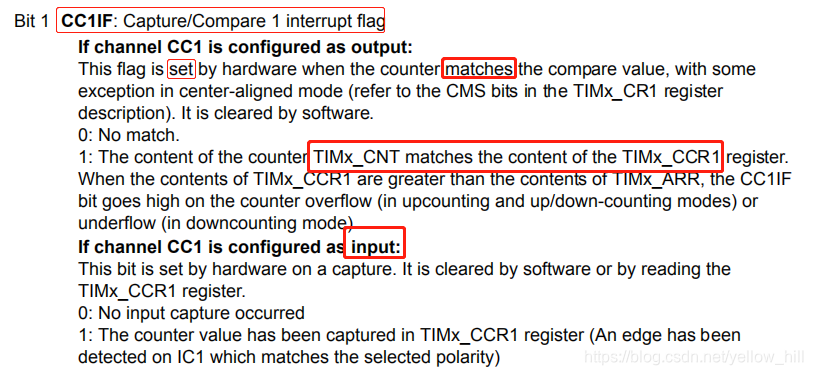
1.1.4 比较脉冲
Compare pulse: the trigger output sends a positive pulse when the CC1IF flag is set (even if it was already high) as soon as a capture or a compare match occurs
比较plus,触发输出一个正脉冲,
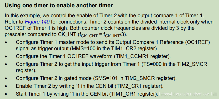
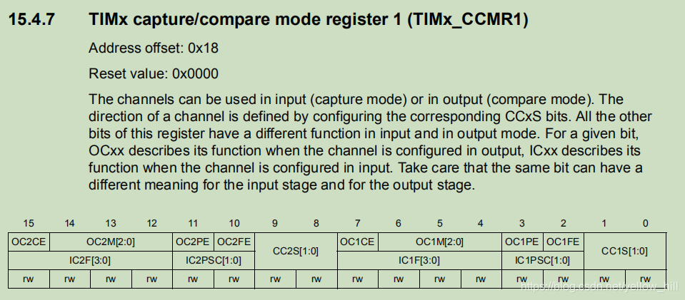
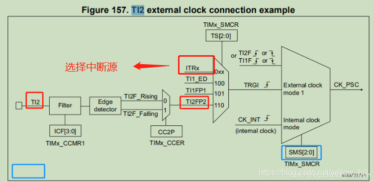
• OC1Ref: OC1REF signal is used as trigger output (TRGO)
OC1Ref,Output compare 1 Reference. 输出比较查看寄存器。
笔者案:下面为OC1Ref的一个控制例子:
T1设定的OC1REF(输出比较参考)作为触发信号的设定信号给出后到另外一个定时器T2,OC1REF的设定由TIM1的CCMR1完成。(设定连接的Mapping和设定值的装载和清除)
• OC2Ref: OC2REF signal is used as trigger output (TRGO)
• OC3Ref: OC3REF signal is used as trigger output (TRGO)
• OC4Ref: OC4REF signal is used as trigger output (TRGO)
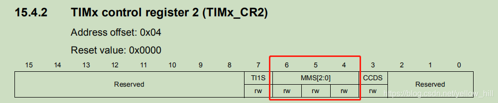
To configure the timer event or internal signal to be used as a synchronization output, the right value should be written to the MMS (master mode selection) control bit-field within the TIMx_CR2 timer control register 2.
要配置定时器事件或者内部信号作为同步的输出,正确的值需要通过MMS寄出去的控制位来进行。
1.2 Timer-slave configuration(定时从模式配置)
Each timer peripheral that embeds a master/slave controller unit features four synchronization inputs already connected to the other timers synchronization outputs.
每个分离的定时器,具备主从控制单元具备上述4中同步输入已经连接到其他定时器的输出。
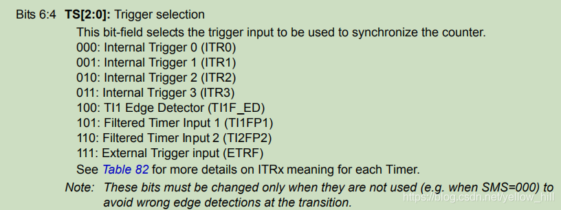
Note that only one synchronization input can be active at each time and the TS (trigger selection) control bit-field is used to select which synchronization input is the active one.
注意,每个定时器只有一个同步信号的输入可以使能,用TS的控制位去选择哪个同步输入。
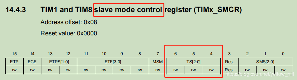
我们看一下SMCR的TS设置:
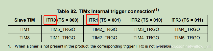
我们看ITR0,这里可以选择被TIM5的TRGO接入。
TIM1 可以被2,3,4,5来作为从timer被触发。
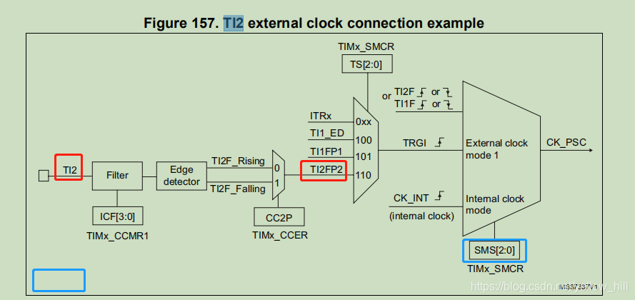
The detection of an active edge on the synchronization input of one timer peripheral may trigger one of timer event inside the peripheral like an “update event” and counter reset, or counter increment.
检测某个定时器输入同步的使能边沿输入可以触发另外一个定时器的事件。
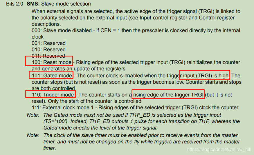
This depends on the configured value into the SMS (slave mode selection) control bit-field within the timer slave mode control register (TIMx_SMCR).
至于触发哪个类型的事件,有SMS控制位来决定。
To select which synchronization input to use, the slave timer is connected to the master timer through the input trigger.
1.3 STM32 timer-commutation feature(定时器的通讯功能 - 预加载设计)
The commutation feature is used in combination with the preload feature to change the timer channel-configuration in perfect synchronization with timer external events that are fed into it through one of its internal or external inputs.
预加载绑定给定时器,这样可以使得定时器的配置通道可以完美的适应于拓展的时间和内部外面的事件输入。
The configuration to which this refer, can be for example channel output mode, channel enabled/disabled or other. ITRx inputs are an example of internal inputs and ETR, TI1, or TI2 are examples of external inputs.
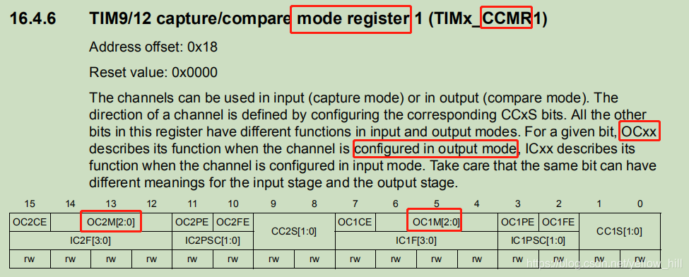
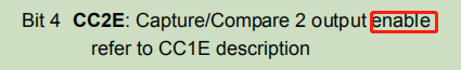
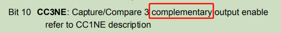
As stated in Section 1: Basic operating modes of STM32 general-purpose timers, the OCxM, CCxE and CCxNE control bit-fields feature the preload capability.
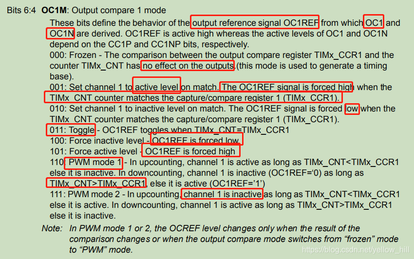
OCxM: output compare mode x:
STM32的功能强大,寄存器的复用也非常多,这个OCXM就是CCMRx里面配置output模式的寄存器:
配置好了之后,是使能寄存器控制:
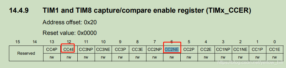
CCxE 使能
CCxNE
When the preload feature on these bit-fields is enabled, any write access to them does not change the timer channel operating mode. The reason is that the write operation is performed on the preload instances of these control bit-fields. Their active instances, which effectively control the timer channel output mode, remain unchanged.Each ITRx is connected internally to another timer, and this connection is specific for each STM32 product.
当preload功能使能后,对这些寄存器的访问都不会改变定时器配置通道的操作模式。因为,写操作处理的是这些控制位的实例,他们的控制定时器输出通道的有效实例不会被改变。
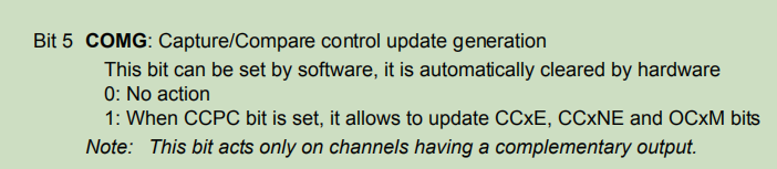
As soon as a commutation event is generated inside the timer, the content of the preload instances of these control bit-fields is transferred into the active instances and consequentially the channel output mode may be changed.
一旦触发事件发生,设置值就会立即反馈到通道的输出上。
Depending on the configuration of the CCUS control bit-field within the timer control register 2 (TIMx_CR2), the commutation event can be generated after detecting an active edge on the timer trigger input signal (TRGI).
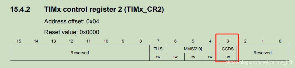
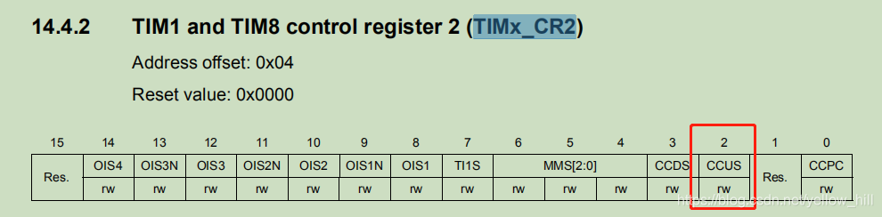
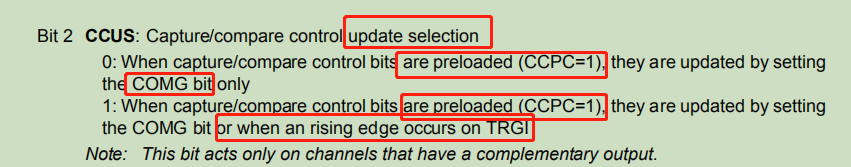
通过配置CCUS,可以将timer trigger input signal (TRGI).设定为边缘触发。
In particular, it can be generated after detecting an active edge on the timer active synchronization ITRx input of the timer peripheral (ITRx inputs are part of the sources of TRGI signal).
再特殊一点,就是当探测到一个ITRX 定时器的活动边沿的时候,产生输出。
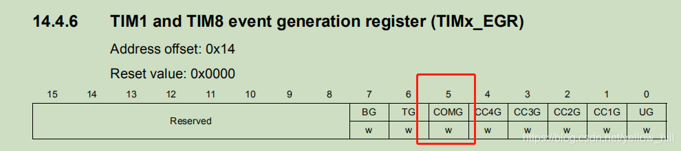
This capability may be used to make one timer control when a commutation event on a second timer should be triggered through inter-timers synchronization. Alternatively, the commutation event may be generated by software through the setting of the COMG control bit-field within the TIMx_EGR timer register.
这个功能可以把两个定时器串起来,软件设定事件产生寄存器,可以拿到


 2111
2111

 被折叠的 条评论
为什么被折叠?
被折叠的 条评论
为什么被折叠?
 到【灌水乐园】发言


