


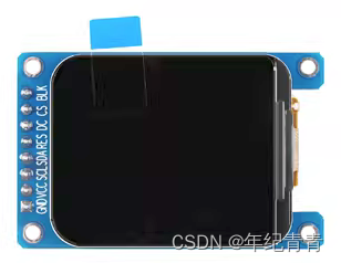
屏幕介绍
本文以中景园
1.69寸LCD,驱动芯片ST7789V2该款屏幕示例,屏幕的分辨率为240*280
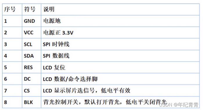
屏幕引脚说明
NanoPi NEO IO介绍
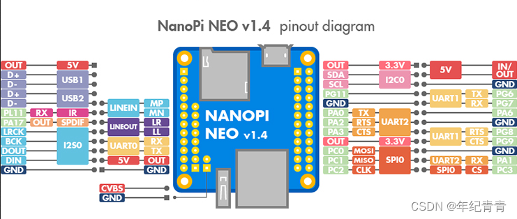
屏幕与板子的IO连接关系
| 屏幕 | NanoPi NEO |
|---|---|
| GND | GND |
| VCC | 3.3V |
| SCL | PC2 |
| SDA | PC0 |
| RES | PG11 |
| DC | PA1 |
| CS | PC3 |
| BLK | PA0 |
下载交叉编译器和linux内核源码并按教程配置好开发环境
参考友善官方链接:Building U-boot and Linux for H5/H3/H2+/zh
修改设备树
需要修改的设备树文件路径:
linux/arch/arm/boot/dts/sun8i-h3-nanopi.dtsi
找到其中spi0节点,修改为如下:
&spi0 {
    /* needed to avoid dtc warning */
    #address-cells = <1>;
    #size-cells = <0>;

    status = "okay";
    pinctrl-names = "default";
    pinctrl-0 = <&spi0_pins &spi0_cs_pins>;
    cs-gpios = <&pio 2 3 GPIO_ACTIVE_HIGH>, <&pio 0 6 GPIO_ACTIVE_HIGH>;

    spidev0: spi@0 {
        compatible = "nanopi,spidev";
        reg = <0>;
        status = "disabled";

        spi-max-frequency = <10000000>;
    };

    spiflash: spiflash@0 {
        #address-cells = <1>;
        #size-cells = <1>;
        compatible = "mxicy,mx25l12805d";
        reg = <0>;
        status = "disabled";

        spi-max-frequency = <50000000>;
        mode = <0>;

        partition@0 {
            reg = <0x0 0x1000000>;
            label = "spi-flash";
        };
    };

    pitft: pitft@0{
        compatible = "sitronix,st7789v";
        reg = <0>;
        status = "okay"; /* 使能 */

        spi-max-frequency = <96000000>; /* 修改了默认速度 */
        rotate = <90>;/* 初始默认旋转了90度 横屏 */
        fps = <33>;
        buswidth = <8>;
        dc-gpios = <&pio 0 1 GPIO_ACTIVE_HIGH>;  /* PA1 */
        reset-gpios = <&pio 6 11 GPIO_ACTIVE_HIGH>; /* PG11 */
        led-gpios = <&pio 0 0 GPIO_ACTIVE_LOW>;  /* PA0 */
        debug = <0x0>;
    };

    pitft_ts: pitft-ts@1 {
        compatible = "ti,ads7846";
        reg = <1>;
        status = "disabled";

        spi-max-frequency = <2000000>;
        interrupt-parent = <&pio>;
        interrupts = <6 9 IRQ_TYPE_EDGE_FALLING>;   /* PG9 / EINT9 */
        pendown-gpio = <&pio 6 9 GPIO_ACTIVE_LOW>;
        ti,swap-xy;
        ti,vref-delay-usecs = <1000>;
        ti,x-min = /bits/ 16 <100>;
        ti,x-max = /bits/ 16 <0xfff>;
        ti,y-min = /bits/ 16 <100>;
        ti,y-max = /bits/ 16 <0xfff>;
        ti,vref-mv = <3300>;
        ti,x-plate-ohms = /bits/ 16 <256>;
        ti,penirq-recheck-delay-usecs = <10>;
        ti,settle-delay-usec = /bits/ 16 <100>;
        ti,keep-vref-on = <1>;
        ti,pressure-max = /bits/ 16 <0xfff>;
        ti,debounce-max = <10>;
        ti,debounce-tol = <30>;
        ti,debounce-rep = <1>;
    };
};
找到pio节点,添加屏幕其它控制引脚的io
&pio {
    leds_npi: led_pins {
        pins = "PA10";
        function = "gpio_out";
    };
    lcd_reset_pins: lcd_reset_pins {
        pins = "PG11";
        function = "gpio_out";
    };

    lcd_dc_pins: lcd_dc_pins {
        pins = "PA1";
        function = "gpio_out";
    };

    lcd_led_pins: lcd_led_pins {
        pins = "PA0";
        function = "gpio_out";
    };
    spi0_cs_pins: spi0_cs_pins {
        pins = "PC3", "PA6";
        function = "gpio_out";
    };
};
禁用hdmi音频视频输出,否则屏幕不显示
&hdmi {
    #status = "okay";
    status = "disabled";
};

&hdmi_out {
    hdmi_out_con: endpoint {
        remote-endpoint = <&hdmi_con_in>;
    };
};

&sound_hdmi {
    #status = "okay";
    status = "disabled";
};
修改驱动文件
linux/drivers/staging/fbtft/路径下,找到fb_st7789v.c,根据自己屏幕情况修改相关参数本人移植时,出现屏幕颜色不对,坐标偏移等情况,根据中景园提供的驱动程序对该文件进行了一定修改,本人用途屏幕旋转90度横屏使用,只做了横屏坐标校准,其它旋转角度下坐标不准只需要修改set_addr_win函数内的坐标偏移即可,至此代码修改内容全部完成
/*
 * FB driver for the ST7789V LCD Controller
 *
 * Copyright (C) 2015 Dennis Menschel
 *
 * This program is free software; you can redistribute it and/or modify
 * it under the terms of the GNU General Public License as published by
 * the Free Software Foundation; either version 2 of the License, or
 * (at your option) any later version.
 *
 * This program is distributed in the hope that it will be useful,
 * but WITHOUT ANY WARRANTY; without even the implied warranty of
 * MERCHANTABILITY or FITNESS FOR A PARTICULAR PURPOSE.  See the
 * GNU General Public License for more details.
 */

#include <linux/bitops.h>
#include <linux/delay.h>
#include <linux/init.h>
#include <linux/kernel.h>
#include <linux/module.h>
#include <video/mipi_display.h>
#include <linux/gpio.h>

#include "fbtft.h"

#define DRVNAME "fb_st7789v"

#define DEFAULT_GAMMA \
    "70 2C 2E 15 10 09 48 33 53 0B 19 18 20 25\n" \
    "70 2C 2E 15 10 09 48 33 53 0B 19 18 20 25"

/**
 * enum st7789v_command - ST7789V display controller commands
 *
 * @PORCTRL: porch setting
 * @GCTRL: gate control
 * @VCOMS: VCOM setting
 * @VDVVRHEN: VDV and VRH command enable
 * @VRHS: VRH set
 * @VDVS: VDV set
 * @VCMOFSET: VCOM offset set
 * @PWCTRL1: power control 1
 * @PVGAMCTRL: positive voltage gamma control
 * @NVGAMCTRL: negative voltage gamma control
 *
 * The command names are the same as those found in the datasheet to ease
 * looking up their semantics and usage.
 *
 * Note that the ST7789V display controller offers quite a few more commands
 * which have been omitted from this list as they are not used at the moment.
 * Furthermore, commands that are compliant with the MIPI DCS have been left
 * out as well to avoid duplicate entries.
 */
enum st7789v_command {
    PORCTRL = 0xB2,
    GCTRL = 0xB7,
    VCOMS = 0xBB,
    VDVVRHEN = 0xC2,
    VRHS = 0xC3,
    VDVS = 0xC4,
    VCMOFSET = 0xC5,
    PWCTRL1 = 0xD0,
    PVGAMCTRL = 0xE0,
    NVGAMCTRL = 0xE1,
};

#define MADCTL_BGR BIT(3) /* bitmask for RGB/BGR order */
#define MADCTL_MV BIT(5) /* bitmask for page/column order */
#define MADCTL_MX BIT(6) /* bitmask for column address order */
#define MADCTL_MY BIT(7) /* bitmask for page address order */

/**
 * init_display() - initialize the display controller
 *
 * @par: FBTFT parameter object
 *
 * Most of the commands in this init function set their parameters to the
 * same default values which are already in place after the display has been
 * powered up. (The main exception to this rule is the pixel format which
 * would default to 18 instead of 16 bit per pixel.)
 * Nonetheless, this sequence can be used as a template for concrete
 * displays which usually need some adjustments.
 *
 * Return: 0 on success, < 0 if error occurred.
 */
static int init_display(struct fbtft_par *par)
{
    /* turn off sleep mode */
    write_reg(par, MIPI_DCS_EXIT_SLEEP_MODE);
    mdelay(120);
#if 0
    /* set pixel format to RGB-565 */
    write_reg(par, MIPI_DCS_SET_PIXEL_FORMAT, MIPI_DCS_PIXEL_FMT_16BIT);

    write_reg(par, PORCTRL, 0x08, 0x08, 0x00, 0x22, 0x22);

    /*
     * VGH = 13.26V
     * VGL = -10.43V
     */
    write_reg(par, GCTRL, 0x35);

    /*
     * VDV and VRH register values come from command write
     * (instead of NVM)
     */
    write_reg(par, VDVVRHEN, 0x01, 0xFF);

    /*
     * VAP =  4.1V + (VCOM + VCOM offset + 0.5 * VDV)
     * VAN = -4.1V + (VCOM + VCOM offset + 0.5 * VDV)
     */
    write_reg(par, VRHS, 0x0B);

    /* VDV = 0V */
    write_reg(par, VDVS, 0x20);

    /* VCOM = 0.9V */
    write_reg(par, VCOMS, 0x20);

    /* VCOM offset = 0V */
    write_reg(par, VCMOFSET, 0x20);

    /*
     * AVDD = 6.8V
     * AVCL = -4.8V
     * VDS = 2.3V
     */
    write_reg(par, PWCTRL1, 0xA4, 0xA1);
    write_reg(par, MIPI_DCS_SET_DISPLAY_ON);
    #endif

    write_reg(par, 0x3A,0x05);

    write_reg(par, 0xB2,0x0C,0x0C,0x00,0x33,0x33);
    write_reg(par, 0xB7,0x35);
    write_reg(par, 0xBB,0x32);
    write_reg(par, 0xC2,0x01);

    write_reg(par, 0xC3,0x15);

    write_reg(par, 0xC4,0x20);

    write_reg(par, 0xC6,0x0F);
    write_reg(par, 0xD0,0xA4,0xA1);
        write_reg(par,PVGAMCTRL,0xD0,0x08,0x0E,0x09,0x09,0x05,0x31,0x33,0x48,0x17,0x14,0x15,0x31,0x34);
        write_reg(par,NVGAMCTRL, 0xD0,0x08,0x0E,0x09,0x09,0x15,0x31,0x33,0x48,0x17,0x14,0x15,0x31,0x34);
    write_reg(par,0x21);

    write_reg(par,0x29);
    return 0;
}

/**
 * set_var() - apply LCD properties like rotation and BGR mode
 *
 * @par: FBTFT parameter object
 *
 * Return: 0 on success, < 0 if error occurred.
 */
static int set_var(struct fbtft_par *par)
{
    u8 madctl_par = 0;

    if (par->bgr)
        madctl_par |= MADCTL_BGR;
    switch (par->info->var.rotate) {
    case 0:
        break;
    case 90:
        madctl_par |= (MADCTL_MV | MADCTL_MY);
        break;
    case 180:
        madctl_par |= (MADCTL_MX | MADCTL_MY);
        break;
    case 270:
        madctl_par |= (MADCTL_MV | MADCTL_MX);
        break;
     default:
        return -EINVAL;
    }
    write_reg(par, MIPI_DCS_SET_ADDRESS_MODE, madctl_par);
    return 0;
}

/**
 * set_gamma() - set gamma curves
 *
 * @par: FBTFT parameter object
 * @curves: gamma curves
 *
 * Before the gamma curves are applied, they are preprocessed with a bitmask
 * to ensure syntactically correct input for the display controller.
 * This implies that the curves input parameter might be changed by this
 * function and that illegal gamma values are auto-corrected and not
 * reported as errors.
 *
 * Return: 0 on success, < 0 if error occurred.
 */
static int set_gamma(struct fbtft_par *par, u32 *curves)
{
    int i;
    int j;
    int c; /* curve index offset */

    /*
     * Bitmasks for gamma curve command parameters.
     * The masks are the same for both positive and negative voltage
     * gamma curves.
     */
    static const u8 gamma_par_mask[] = {
        0xFF, /* V63[3:0], V0[3:0]*/
        0x3F, /* V1[5:0] */
        0x3F, /* V2[5:0] */
        0x1F, /* V4[4:0] */
        0x1F, /* V6[4:0] */
        0x3F, /* J0[1:0], V13[3:0] */
        0x7F, /* V20[6:0] */
        0x77, /* V36[2:0], V27[2:0] */
        0x7F, /* V43[6:0] */
        0x3F, /* J1[1:0], V50[3:0] */
        0x1F, /* V57[4:0] */
        0x1F, /* V59[4:0] */
        0x3F, /* V61[5:0] */
        0x3F, /* V62[5:0] */
    };

    for (i = 0; i < par->gamma.num_curves; i++) {
        c = i * par->gamma.num_values;
        for (j = 0; j < par->gamma.num_values; j++)
            curves[c + j] &= gamma_par_mask[j];
        write_reg(
            par, PVGAMCTRL + i,
            curves[c + 0], curves[c + 1], curves[c + 2],
            curves[c + 3], curves[c + 4], curves[c + 5],
            curves[c + 6], curves[c + 7], curves[c + 8],
            curves[c + 9], curves[c + 10], curves[c + 11],
            curves[c + 12], curves[c + 13]);
    }
    return 0;
}
static void set_addr_win(struct fbtft_par *par, int xs, int ys, int xe, int ye)
{
    switch(par->info->var.rotate)
    {
        case   0: xs+=0;xe+=0;ys+=0;ye+=0;
                 break;
        case  90: xs+=20;xe+=20;ys+=0;ye+=0;
                 break;
        case 180: xs+=0;xe+=0;ys+=80;ye+=80;
                 break;
        case 270: xs+=0;xe+=0;ys+=53;ye+=53;
                 break;
        default :
                 break;
    }

    write_reg(par, MIPI_DCS_SET_COLUMN_ADDRESS,
          xs >> 8, xs & 0xFF, xe >> 8, xe & 0xFF);

    write_reg(par, MIPI_DCS_SET_PAGE_ADDRESS,
          ys >> 8, ys & 0xFF, ye >> 8, ye & 0xFF);

    write_reg(par, MIPI_DCS_WRITE_MEMORY_START);
}

/**
 * blank() - blank the display
 *
 * @par: FBTFT parameter object
 * @on: whether to enable or disable blanking the display
 *
 * Return: 0 on success, < 0 if error occurred.
 */
static int blank(struct fbtft_par *par, bool on)
{
    if (on)
        write_reg(par, MIPI_DCS_SET_DISPLAY_OFF);
    else
        write_reg(par, MIPI_DCS_SET_DISPLAY_ON);
    return 0;
}

static struct fbtft_display display = {
    .regwidth = 8,
    .width = 240,
    .height = 280,
    .gamma_num = 2,
    .gamma_len = 14,
    .gamma = DEFAULT_GAMMA,
    .fbtftops = {
        .init_display = init_display,
        .set_var = set_var,
        .set_addr_win = set_addr_win,
        .set_gamma = set_gamma,
        .blank = blank,
    },
};

FBTFT_REGISTER_DRIVER(DRVNAME, "sitronix,st7789v", &display);

MODULE_ALIAS("spi:" DRVNAME);
MODULE_ALIAS("platform:" DRVNAME);
MODULE_ALIAS("spi:st7789v");
MODULE_ALIAS("platform:st7789v");

MODULE_DESCRIPTION("FB driver for the ST7789V LCD Controller");
MODULE_AUTHOR("Dennis Menschel");
MODULE_LICENSE("GPL");
使用menuconfig使能该驱动
在
linux源码根目录下执行
make menuconfig ARCH=arm CROSS_COMPILE=arm-linux-
Device Drivers  --->
	[*] Staging drivers  --->
		<*>   Support for small TFT LCD display modules  --->
			<*> FB driver for the ST7789V LCD Controller
编译内核设备树
# 编译内核、设备树、模块
make zImage dtbs modules ARCH=arm CROSS_COMPILE=arm-linux-
更新板子内核和设备树文件
将
arch/arm/boot/zImage内核镜像文件和arch/arm/boot/dts/sun8i-h3-nanopi-neo.dtb设备树文件拷贝到板子的/boot目录下,使用内存卡拷贝或者网络传输都可以,这里以网络更新为例
scp arch/arm/boot/zImage root@192.168.31.88:/boot
scp arch/arm/boot/dts/sun8i-h3-nanopi-neo.dtb root@192.168.31.88:/boot
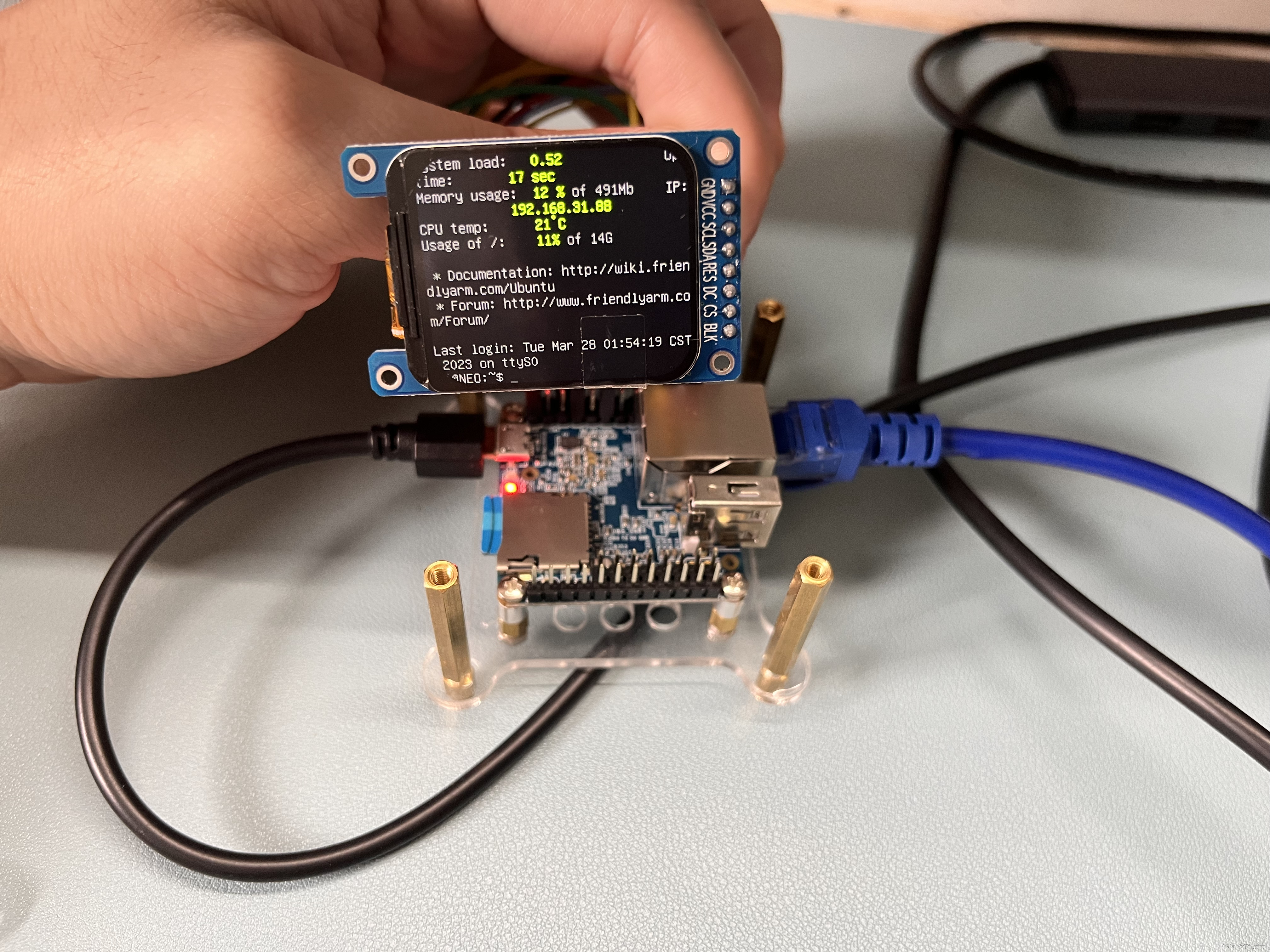
重启板子后屏幕可以出现内核启动和linux终端画面
这里开机logo已经修改,原系统是三只linux企鹅图标


后期玩法
画一张带屏幕的接口板与板子组合成一体,可以移植
lvgl或者QT,真正变成一个小电脑


 2万+
2万+


 被折叠的 条评论
为什么被折叠?
被折叠的 条评论
为什么被折叠?
 到【灌水乐园】发言


