


【计算机图形学】Viewing 部分问题与解答
- CS100433 Computer Graphics Assignment 2
- 1 Proof the composed transformations defined in global coordinate frame is equivalent to the composed transformations defined in local coordinate frame but in different composing order.
- 2 Describe the differences between orthographic and perspective 3D viewing processes? (Draw the view volume of the above two viewings)
- 3 Which one defines the default NDC? Why?
- 4 What is the difference between the clip space and NDC?
- 5 Why does clipping performed in the clip space?
- 6 What is the cause of Z-fighting? And can we solve the Z-fighting?
如果这篇文章对你有帮助,欢迎点赞与收藏~
CS100433 Computer Graphics Assignment 2
1 Proof the composed transformations defined in global coordinate frame is equivalent to the composed transformations defined in local coordinate frame but in different composing order.
- Global (or World) Frame Transformations: Transformations are applied relative to a fixed global/world coordinate frame. When multiple transformations are applied, they are composed in the same order that they are applied to the point or object.
- Local (or Body or Object) Frame Transformations: Transformations are applied relative to the object’s own local coordinate frame. As the object moves, its local frame moves with it. When multiple transformations are applied, the order of composition is typically reversed because each subsequent transformation is applied in the new local frame created by the previous transformation.
2 Describe the differences between orthographic and perspective 3D viewing processes? (Draw the view volume of the above two viewings)
Orthographic Projection:
- In orthographic projection, all projection lines are parallel. Objects are projected to the viewing plane at the same size, regardless of their distance from the viewer.
- Orthographic projection does not exhibit perspective effects; that is, the size of objects on the viewing plane does not change with distance. Objects far away appear the same size as those that are near.
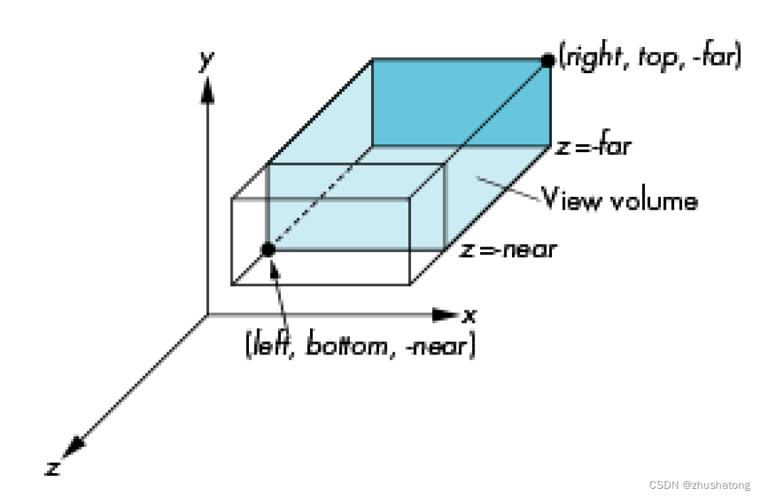
- The view volume for orthographic projection is a rectangular box, often referred to as a “view frustum,” although in the case of orthographic projection, it’s technically a rectangular prism.
- Orthographic projection is commonly used in engineering drawings and certain types of games (like 2D platformers), as it accurately reflects dimensions and angles without distortion.
Perspective Projection:
- In perspective projection, projection lines radiate from a point (the viewer’s eye) and spread outward, causing objects that are further away to appear smaller, creating a sense of depth.
- This type of projection mimics the way the human eye observes the world, with closer objects appearing larger and distant objects appearing smaller.
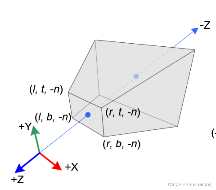
- The view volume for perspective projection is a truncated pyramid, with the apex at the viewer’s eye and the base corresponding to the far clipping plane.
- Perspective projection is used in most 3D games and simulation environments because it provides a more natural three-dimensional appearance.
3 Which one defines the default NDC? Why?
glm::ortho(-1., 1., -1., 1., -1., 1.)
glm::ortho(-1., 1., -1., 1., 1., -1.)
Between glm::ortho(-1., 1., -1., 1., -1., 1.) and glm::ortho(-1., 1., -1., 1., 1., -1.), the latter defines the default NDC in OpenGL. This is because the NDC in OpenGL follows a left-hand coordinate frame where the positive Z-axis points out of the screen. The parameters for zNear and zFar in the glm::ortho function represent distances measured in the direction of the camera. So, in the latter function, with zNear set to 1 and zFar set to -1, it signifies that the near clipping plane is closer to the camera while the far clipping plane is farther away, consistent with the default behavior of OpenGL’s NDC.
4 What is the difference between the clip space and NDC?
Clip Space:
- Clip space is encountered after the projection transformation has been applied to the vertices of objects in the scene but before the perspective division.
- It is a four-dimensional space because it includes the homogeneous coordinate
walongside the usual x, y, and z coordinates. The value ofwis not necessarily 1; it could be any value depending on the depth and the type of projection used (orthographic or perspective). - In clip space, the graphics system can perform clipping to discard geometry that is outside the viewer’s field of view or behind the camera. This is because the clip space is configured in such a way that any coordinates outside a certain range can be easily identified and excluded from the final image.
Normalized Device Coordinates (NDC):
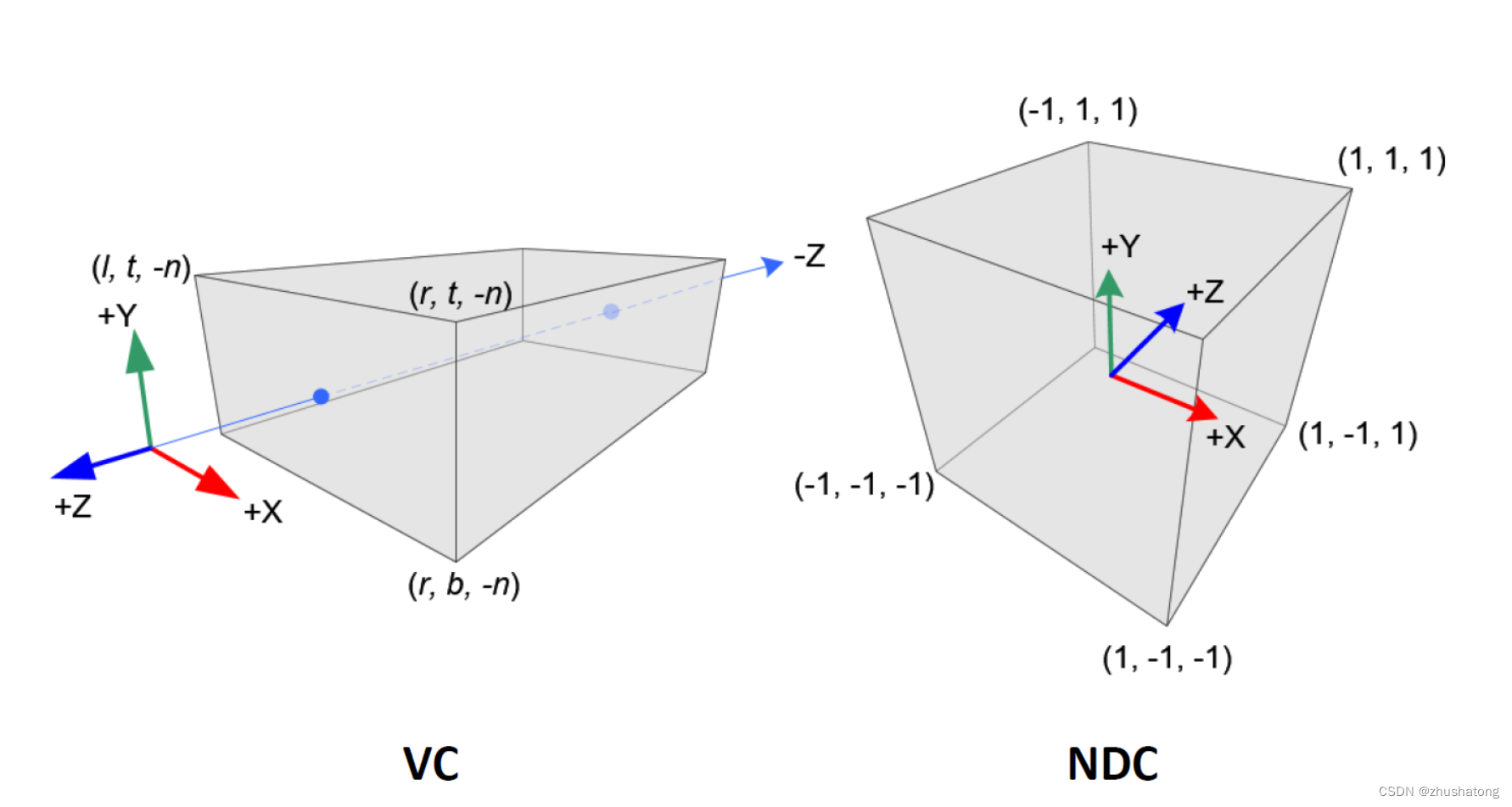
- After the vertices have been transformed to clip space and clipping has been performed, the perspective division is applied. This process involves dividing the x, y, and z coordinates by the w coordinate. The result of this division is the NDC space.
- In NDC, the homogeneous coordinate
wis now equal to 1. This effectively reduces the dimensionality back to three, making it suitable for the final step of rasterization, which maps these coordinates onto the two-dimensional viewport or screen. - The NDC space is a cubic volume where the x, y, and z coordinates range from -1 to 1. Any point within this range can be mapped directly to the viewport.
5 Why does clipping performed in the clip space?
- Efficiency: Clip space is a standardized and regular space, which makes it easier and more efficient to determine if an object is within the view frustum. Objects can be quickly tested against the boundaries of this space because, after projection but before the perspective division, the clip space is aligned with the view frustum. This means any coordinates that fall outside this regular volume can be efficiently identified and discarded.
- Correctness: In clip space, the original depth information of a vertex is preserved in the w component of its homogeneous coordinates. This is crucial because clipping decisions must be made based on accurate depth information to ensure that objects are correctly rendered in three dimensions. After perspective division, which converts clip space coordinates into normalized device coordinates (NDC), depth information is normalized. In NDC, all coordinates are compressed into a standard range (usually between -1 and 1), which is great for the next stages of rasterization but not for making depth-based clipping decisions.
6 What is the cause of Z-fighting? And can we solve the Z-fighting?
Z-fighting occurs due to the nonlinear interpolation of depth along the z-axis during normalization. Because the resolution of depth decreases for coordinates further from the nearest clipping plane, this can lead to precision issues in the depth buffer. When two surfaces are very close together and their depth values are nearly identical, the renderer might struggle to consistently determine which surface should be displayed over the other. This results in a flickering or stitching effect in the rendered image, known as Z-fighting.
To address the issue of Z-fighting, the following solutions can be implemented:
- Push the nearest clipping plane further away: By moving the nearest clipping plane backward as far as possible without significantly sacrificing the visible area, the density of depth buffer near the front can be reduced, which may alleviate the Z-fighting to some extent.
- Increase the precision of the Z-buffer: Using a depth buffer with more bits can increase the precision of depth values. For example, upgrading from a 16-bit to a 24-bit or 32-bit depth buffer can significantly reduce the occurrence of Z-fighting. This method increases the storage requirements and potential performance costs but can effectively mitigate the problem.


 1076
1076


 被折叠的 条评论
为什么被折叠?
被折叠的 条评论
为什么被折叠?
 到【灌水乐园】发言


