


摘录风火轮WikiTinker board 2 Debian下 MIPI-DSI屏幕的适配方法 | 风火轮Wiki (smartfire.cn)
简单介绍一下目前 RK3399的显示框架。目前的Debian采用的都是Linux DRM框架进行显示,在DRM框架中,其显示通路如下图所示
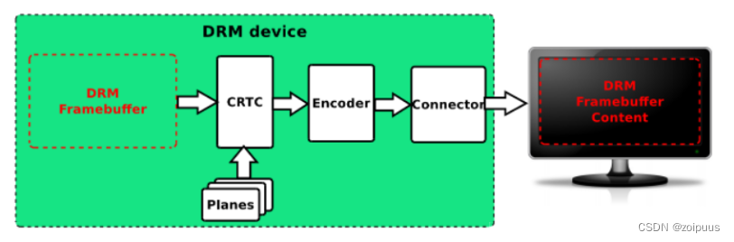
图中的几个组成部分
Framebuffer:显存,嵌入式系统使用的是内存的一部分
CRTC:显示控制器,在RK3399平台是SOC 内部VOP,RK3399里面包含两个VOP;
Encoder:输出转换器,指RGB、LVDS、DSI、eDP、HDMI、CVBS、VGA 等显示接口,它本质就是一个编码器,将CRTC提供过来的信号编码为对应显示接口需要的信号。
Connector:连接器,指encoder 和panel 之间交互的接口部分;
Panel:各种具体的屏幕
因此,要驱动DSI屏幕,有三个部分需要配置,包括VOP,DSI控制器,屏幕的参数。
开启vopb与vopl,设置时钟与MMU
&vopb {
        status = "okay";
        assigned-clocks = <&cru DCLK_VOP0_DIV>;
        assigned-clock-parents = <&cru PLL_VPLL>;
};

&vopb_mmu {
        status = "okay";
};

&vopl {
        status = "okay";
        assigned-clocks = <&cru DCLK_VOP1_DIV>;
        assigned-clock-parents = <&cru PLL_CPLL>;
};

&vopl_mmu {
        status = "okay";
};
设置vop与显示接口之间的绑定关系
&route_hdmi {
        status = "okay";
        connect = <&vopb_out_hdmi>;
};

&route_dsi{
        status = "okay";
        connect = <&vopl_out_dsi>;
};
DSI和panel的配置
 &dsi {
        status = "okay";
+       //配置dsi每个lane的频率,一般出现花屏,条纹等可以调整这个值改善
+       //如果这个值不配置,DSI驱动会自动计算
+       rockchip,lane-rate = <500>;
        panel@0 {
-               compatible ="simple-panel-dsi";
+               status = "okay";
+               compatible = "simple-panel-dsi";
                reg = <0>;
+               //背光,即使不启用背光调节功能,这个属性也必须配置,且backlight的节点必须是有效的
+               //否则驱动会加载失败
+               backlight = <&backlight>;
+               //使能脚,如果enable 接到一个gpio,这个属性必须设置
+               enable-gpios = <&gpio0 6 GPIO_ACTIVE_LOW>;
+
+               width-mm = <476>;
+               height-mm = <267>;
+               bpc=<8>;
+               bus-format = <0x100a>;//<MEDIA_BUS_FMT_RGB888_1X24>;
+               dsi,flags = <0x3>;
+               dsi,format = <0>;//MIPI_DSI_FMT_RGB888:
+               dsi,lanes = <4>;
+               panel-init-sequence = [
+                       15 00 02 80 ac
+                       15 00 02 81 b8
+                       15 00 02 82 09
+                       15 00 02 83 78
+                       15 00 02 84 7f
+                       15 00 02 85 bb
+                       15 00 02 86 70
+               ];

                rpi-init-sequence = [
                                29 00 06 10 02 03 00 00 00
@@ -739,6 +770,26 @@
                        };
                };

+               display-timings {
+                       native-mode = <&timing10>;
+                       timing10: timing10  {
+                               clock-frequency = <65000000>; //DCLK
+                               hactive = <1024>;             //hactive
+                               vactive = <600>;              //vactive
+                               hfront-porch = <160>;         //hfp
+                               hback-porch = <160>;          //hbp
+                               hsync-len = <10>;             //hsa
+                               vfront-porch = <12>;          //vfp
+                               vsync-len = <1>;              //vsa
+                               vback-porch = <23>;           //vbp
+                               hsync-active = <0>;           //hync 极性控制 置 1 反转极性
+                               vsync-active = <0>;           //vsync 极性控制 置 1 反转极性
+                               de-active = <1>;              //DEN 极性控制
+                               pixelclk-active = <0>;        //dclk 极性控制
+                       };
+               };
panel的配置,是参考风火轮的wiki, http://wiki.smartfire.cn/Tinkerboard2/lcd
触摸驱动配置&i2c8
+
+       goodix_ts@14 {
+               compatible = "goodix,gt9xx";
+               reg = <0x14>;
+               touch-gpio = <&gpio2 RK_PC3 GPIO_ACTIVE_LOW>;
+               reset-gpio = <&gpio2 RK_PC2 GPIO_ACTIVE_LOW>;
+               max-x = <1024>;
+               max-y = <600>;
+               tp-size = <911>;
+               status = "okay";
+       };
 };
1、backlight问题
①pin gpio1-8 already requested by pinctrl; cannot claim for backlight

原因:backlight里面用到的管脚已经被pinctrl用了,修改冲突的管脚,如果没用到可以删除(删除backlight的或者pinctrl的都行)
@@ -1448,15 +1461,46 @@
                post-pwm-on-delay-ms = <15>;//EDP T15,min 10ms, Backlight node:post-pwm-on-delay-ms = <15>;
                pwm-off-delay-ms = <15>;//EDP T16,min 10ms, Backlight node:pwm-off-delay-ms = <15>;
                disable_delay = <15>;//EDP T17,min 10
-               pinctrl-names = "default";
-               pinctrl-0 = <&pinctrl_lvds_bl_en>;
 };
@@ -954,10 +1006,6 @@
gpio_init_config {
gpio_init: gpio_init {
rockchip,pins =
- <1 7 0 &pcfg_pull_none>,
- <1 8 0 &pcfg_pull_none>,
- <1 9 0 &pcfg_pull_none>,
- <1 10 0 &pcfg_pull_none>,
<2 19 0 &pcfg_pull_none>;
};
};②pwm-backlight backlight: Dropping the link to regulator.0
查看log信息
[    3.018844]  panel_simple_probe+
[    3.021638] panel-simple-dsi ff960000.dsi.0: ff960000.dsi.0 supply power not found, using dummy regulator
[    3.024685] panel-simple-dsi ff960000.dsi.0: ff960000.dsi.0 supply vsp not found, using dummy regulator
[    3.027778] panel-simple-dsi ff960000.dsi.0: ff960000.dsi.0 supply vsn not found, using dummy regulator
[    3.031300] pwm-backlight backlight: backlight supply power not found, using dummy regulator
[    3.034394] pwm-backlight backlight: Linked as a consumer to regulator.0
[    3.037108] pwm-backlight backlight: Dropping the link to regulator.0
[    3.040104] sn65dsi84_is_connected  sn65dsi84 connect = 0
Backligh没有配置对,查一下backlight配置的管脚、pwm是否正确,status是否为okay
@@ -1042,7 +1090,7 @@
 };

 &backlight {
-               status = "disabled";
+               status = "okay";
                compatible = "pwm-backlight";
                pwms = <&pwm0 0 400000 0>;//f=2500 t=400,000ns
                brightness-levels = <
diff --git a/arch/arm64/boot/dts/rockchip/rk3399-tinker_board_2.dtsi b/arch/arm64/boot/dts/rockchip/rk3399-tinker_board_2.dtsi
index e98c554371ca..a49794fe9e0e 100755
--- a/arch/arm64/boot/dts/rockchip/rk3399-tinker_board_2.dtsi
+++ b/arch/arm64/boot/dts/rockchip/rk3399-tinker_board_2.dtsi
@@ -731,7 +731,7 @@
 };

 &pwm0 {
-       status = "disabled";
+       status = "okay";
 };

 &pwm1 {
修改编译后运行log如下:
[    1.837780] pwm-backlight backlight: backlight supply power not found, using dummy regulator
[    1.837874] pwm-backlight backlight: Linked as a consumer to regulator.0
[    1.838160] mpp_service mpp-srv: 00b8be6742e6 author: Ding Wei 2021-09-26 video: rockchip: mpp: fix issue for CONFIG_IOMMU_SUPPORT=n
[    1.838190] mpp_service mpp-srv: probe start
[    1.838594] iommu: Adding device ff660000.rkvdec to group
2、probe of ff960000.dsi.0 failed with error -22
[    1.955121] sn65dsi86_detect fail, 0x0 0x0 0x0 0x0 0x0 0x0 0x0 0x0
[    1.955139] sn65dsi86_detect sn65dsi86->status=0
[    1.955156] sn65dsi86_probe : sn65dsi86 is disconnected!
[    1.957464] sn65dsi84_is_connected  sn65dsi84 connect = 0
[    1.957488]  panel_simple_probe+
[    1.957560] panel-simple-dsi ff960000.dsi.0: ff960000.dsi.0 supply power not found, using dummy regulator
[    1.957631] panel-simple-dsi ff960000.dsi.0: Linked as a consumer to regulator.0
[    1.957696] panel-simple-dsi ff960000.dsi.0: ff960000.dsi.0 supply vsp not found, using dummy regulator
[    1.957787] panel-simple-dsi ff960000.dsi.0: ff960000.dsi.0 supply vsn not found, using dummy regulator
[    1.957900] panel_simple_probe-
[    1.957919] panel_simple_dsi_probe-
[    1.958041] panel-simple-dsi: probe of ff960000.dsi.0 failed with error -22
[    1.958376] midgard ff9a0000.gpu: Linked as a consumer to regulator.12
执行ls -l /sys/class/drm/没看到DSI信息

在panel-simple.c跑到了CONFIG_TINKER_MCU里面了,kernel config的tinker_board_2_defconfig里面没有定义,但还是跑进去了

查了代码发现./drivers/misc/Kconfig里面默认是支持的
config TINKER_MCU
        tristate "tinker mcu"
        default y
        depends on I2C
        help
                Control the power of toshiba tc358762 panel on tinker board.

config TINKER_MCU_ILI9881C
        tristate "tinker mcu ili9881c"
        default y
        depends on I2C
        help
                Control the power of ASUS ili9881c panel on tinker board.
重新在tinker_board_2_defconfig里面不设置值
diff --git a/arch/arm64/configs/tinker_board_2_defconfig b/arch/arm64/configs/tinker_board_2_defconfig
index ed330560cf53..81b0cd7ab7a1 100755
--- a/arch/arm64/configs/tinker_board_2_defconfig
+++ b/arch/arm64/configs/tinker_board_2_defconfig
@@ -483,10 +483,12 @@ CONFIG_ROCKCHIP_ANALOGIX_DP=y
 CONFIG_ROCKCHIP_CDN_DP=y
 CONFIG_ROCKCHIP_DW_HDMI=y
 CONFIG_ROCKCHIP_DW_MIPI_DSI=y
-CONFIG_DRM_PANEL_TOSHIBA_TC358762=y
-CONFIG_DRM_PANEL_ASUS_ILI9881C=y
+# CONFIG_DRM_PANEL_TOSHIBA_TC358762 is not set
+# CONFIG_DRM_PANEL_ASUS_ILI9881C is not set
 CONFIG_DRM_I2C_SN65DSI84=y
 CONFIG_DRM_I2C_SN65DSI86=y
+# CONFIG_TINKER_MCU is not set
+# CONFIG_TINKER_MCU_ILI9881C is not set
 CONFIG_ROCKCHIP_INNO_HDMI=y
 CONFIG_ROCKCHIP_LVDS=y
 CONFIG_ROCKCHIP_DRM_TVE=y
3、LCD可以正常显示
出现这些log说明drm驱动已经能够正常运作
[    1.864582] rockchip-drm display-subsystem: Linked as a consumer to ff8f0000.vop
[    1.864630] rockchip-drm display-subsystem: Linked as a consumer to ff900000.vop
[    1.865445] rockchip-drm display-subsystem: Linked as a consumer to fec00000.dp
[    1.865806] rockchip-drm display-subsystem: Linked as a consumer to ff940000.hdmi
[    1.866175] rockchip-drm display-subsystem: Linked as a consumer to ff960000.dsi
这个log说明dsi控制器已经工作,且已经绑定到drm框架中
[    2.530379] rockchip-drm display-subsystem: bound ff940000.hdmi (ops 0xffffff800911ef10)
[    2.530429] rockchip-drm display-subsystem: bound ff960000.dsi (ops 0xffffff800911fe48)
一般来说输出这个信息,说明dsi控制器和panel已经绑定
[    2.804623] rockchip_rk3399_pll_wait_lock: timeout waiting for pll to lock
[    2.804626] rockchip_rk3399_pll_set_params: pll update unsuccessful, trying to restore old params
[    2.804655] clk_core_set_rate_nolock: failed to set pll_vpll clock to run at 12000000
[    2.804680] rockchip-vop ff8f0000.vop: [drm:vop_crtc_atomic_enable] Update mode to 1024x600p75, type: 16
[    2.804992] rockchip-vop ff900000.vop: [drm:vop_crtc_atomic_enable] Update mode to 1920x1200p60, type: 11
[    2.827330] dwhdmi-rockchip ff940000.hdmi: Rate 193250000 missing; compute N dynamically
[    2.827424] dw-mipi-dsi ff960000.dsi: [drm:dw_mipi_dsi_encoder_enable] final DSI-Link bandwidth: 504 x 4 Mbps
4、屏幕触摸校准
[    0.989699] <<-GTP-INFO->> GTP driver installing...
[    0.989862] goodix_ts_probe() start
[    0.989888] <<-GTP-INFO->> GTP Driver Version: V2.2<2014/01/14>
[    0.989908] <<-GTP-INFO->> GTP I2C Address: 0x14
[    0.989971] Goodix-TS 8-0014: 8-0014 supply tp not found, using dummy regulator
[    0.990037] Goodix-TS 8-0014: Linked as a consumer to regulator.0
[    1.011463] goodix_ts_probe() cfg_file_num = 0
[    1.011530] <<-GTP-INFO->> Guitar reset
[    1.099001] <<-GTP-INFO->> IC Version: 911_1060
[    1.121213] <<-GTP-INFO->>   <gtp_init_panel>_1614
[    1.121233] <<-GTP-INFO->> X_MAX: 4096, Y_MAX: 4096, TRIGGER: 0x00


[   54.197447] #### goodix_ts_work_func() line:974 coor_data[0] input_x:3269 input_y:2704 input_w:11
[   54.197449] #### gtp_touch_down() line:424 gtp_touch_down abs_x_max=4096, abs_y_max=4096
[   54.197454] #### gtp_touch_down() line:427 gtp_touch_down x=3269, y=2704
[   54.197458] #### gtp_touch_down() line:428 gtp_touch_down (!bgt911 && !bgt970)=0
[   54.197461] #### gtp_touch_down() line:437 gtp_touch_down x=3269, y=2704
[   54.197465] #### gtp_touch_down() line:448 GTP_ICS_SLOT_REPORT:0
[   54.197474] #### gtp_touch_down() line:457 ID:0, X:3269, Y:2704, W:11
[   54.197478] <<-GTP-DEBUG->> [458]ID:0, X:3269, Y:2704, W:11
通过打印可以看到屏幕初始化没问题,但是X_MAX和Y_MAX没有从dtsi里面获取到,看代码发现获取参数的地方屏蔽了,如下
+++ b/drivers/input/touchscreen/gt9xx/gt9xx.c
@@ -2664,9 +2664,10 @@ static int goodix_ts_probe(struct i2c_client *client, const struct i2c_device_id
        } else if (val == 911) {
                m89or101 = FALSE;
                bgt911 = TRUE;
-               gtp_change_x2y = TRUE;
+               // gtp_change_x2y = TRUE;
+               gtp_change_x2y = FALSE;
                gtp_x_reverse = FALSE;
-               gtp_y_reverse = TRUE;
+               gtp_y_reverse = FALSE;
        } else if (val == 9110) {
                m89or101 = FALSE;
                bgt9110 = TRUE;
@@ -2716,17 +2717,19 @@ static int goodix_ts_probe(struct i2c_client *client, const struct i2c_device_id
        dev_err(&client->dev, "no max-x defined\n");
        return -EINVAL;
     }
-    //ts->abs_x_max = val;
+    ts->abs_x_max = val;
     if (of_property_read_u32(np, "max-y", &val)) {
        dev_err(&client->dev, "no max-y defined\n");
        return -EINVAL;
     }
-    //ts->abs_y_max = val;
+    ts->abs_y_max = val;
     if (of_property_read_u32(np, "configfile-num", &val)) {
            ts->cfg_file_num = 0;
触摸不准的话需要导入该屏的cfg配置文件
+++ b/drivers/input/touchscreen/gt9xx/gt9xx_cfg.h
@@ -21,7 +21,9 @@
 /* CFG for GT911 */
 u8 gtp_dat_gt11[] = {
        /* <1200, 1920>*/
-       #include "WGJ89006B_GT911_Config_20140625_085816_0X43.cfg"
+       /* #include "WGJ89006B_GT911_Config_20140625_085816_0X43.cfg" */
+       /* <1024, 600>*/
+       #include "WGJ89006B_GT911_Config_20230908_085816_0X43.cfg"
 };

 u8 gtp_dat_gt9110[] = {
TinkerBoard2板卡运行BuildRoot系统
补丁下载地址:


 1002
1002


 被折叠的 条评论
为什么被折叠?
被折叠的 条评论
为什么被折叠?
 到【灌水乐园】发言


