


转:http://blog.chinaaet.com/justlxy/p/5100053463
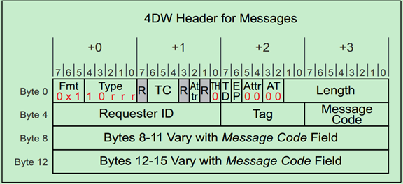
PCIe中的Message主要是为了替代PCI中采用边带信号,这些边带信号的主要功能是中断,错误报告和电源管理等。所有的Message请求采用的都是4DW的TLP Header,但是并不是所有的空间都被利用上了,例如有的Message就没有使用Byte8到Byte15的空间。
Message请求的TLP Header格式如下图所示:


上面的表格中提到了,Message主要有九个类型:
1. INTx Interrupt Signaling
2. Power Management
3. Error Signaling
4. Locked Transaction Support
5. Slot Power Limit Support
6. Vendor‐Defined Messages
7. Ignored Messages (related to Hot‐Plug support in spec revision 1.1)
8. Latency Tolerance Reporting (LTR)
9. Optimized Buffer Flush and Fill (OBFF)
下面将分别进行介绍一下,
INTx Interrupt Messages(中断消息)
PCI 2.3提出了MSI(Message Signaled Interrupt),但是早期的PCI并不支持这一功能,PCIe为此定义了一种Virtual Wire来模拟PCI的中断引脚(INTA-INTD)。如下图所示:

INTx Message的使用规则如下:
· They have no data payload and so the Length field is reserved.
· They’re only issued by Upstream Ports. Checking this rule for received packets is optional but, if checked, violations will be handled as Malformed TLPs.
· They are required to use the default traffic class TC0. Receivers must check for this and violations will be handled as Malformed TLPs.
· Components at both ends of the Link must track the current state of the four virtual interrupts. If the logical state of one interrupt changes at the Upstream Port, it must send the appropriate INTx message.
· INTx signaling is disabled when the Interrupt Disable bit of the Command Register is set = 1 (as would be the case for physical interrupt lines).
· If any virtual INTx signals are active when the Interrupt Disable bit is set in the device, the Upstream Port must send corresponding Deassert_INTx messages.
· Switches must track the state of the four INTx signals independently for each Downstream Port and combine the states for the Upstream Port.
· The Root Complex must track the state of the four INTx lines independently and convert them into system interrupts in an implementation‐specific way.
· They use the routing type “Local‐Terminate at Receiver” to allow a Switch to remap the designated interrupt pin when. Consequently, the Requester ID in an INTx message may be assigned by the last transmitter.
Power Management Messages(电源管理消息)

Power Management Messages使用规则如下:
· Power Management Messages don’t have a data payload, so the Length field is reserved.
· They are required to use the default traffic class TC0. Receivers must check for this and handle violations as Malformed TLPs.
· PM_Active_State_Nak is sent from a Downstream Port after it observes a request from the Link neighbor to change the Link power state to L1 but it has chosen not to do so (Local ‐ Terminate at Receiver routing).
· PM_PME is sent upstream by the component requesting a Power Management Event (Implicitly Routed to the Root Complex).
· PM_Turn_Off is sent downstream to all endpoints (Implicitly Broadcast from the Root Complex routing).
· PME_TO_Ack is sent upstream by endpoints. For switches with multiple Downstream Ports, this message won’t be forwarded upstream until all Downstream Ports have received it (Gather and Route to the Root Complex routing).
Error Messages(错误消息)

Error Message使用规则如下:
· They are required to use the default traffic class TC0. Receivers must check for this and handle violations as Malformed TLPs.
· They don’t have a data payload, so the Length field is reserved.
· The Root Complex converts Error Messages into system‐specific events.
Locked Transaction Support

Unlock Message使用规则:
· They are required to use the default traffic class TC0. Receivers must check for this and handle violations as Malformed TLPs.
· They don’t have a data payload, and the Length field is reserved.
Set Slot Power Limit Message

Set_Slot_Power_Limit Message使用规则:
· They’re required to use the default traffic class TC0. Receivers must check for this and handle violations as Malformed TLPs.
· The data payload is 1 DW and so the Length field is set to one. Only the lower 10 bits of the 32‐bit data payload are used for slot power scaling; the upper payload bits must be set to zero.
· This message is sent automatically anytime the Data Link Layer transitions to DL_Up status or if a configuration write to the Slot Capabilities Register occurs while the Data Link Layer is already reporting DL_Up status.
· If the card in the slot already consumes less power than the power limit specified, it’s allowed to ignore the Message.
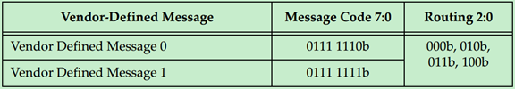
Vendor‐Defined Message 0 and 1

 v
v
厂商自定义Message使用规则:
· A data payload may or may not be included with either type.
· 2. Messages are distinguished by the Vendor ID field.
· 3. Attribute bits [2] and [1:0] are not reserved.
· 4. If the Receiver doesn’t recognize the Message:
• Type 1 Messages are silently discarded
• Type 0 Messages are treated as an Unsupported Request error condition
Ignored Messages

Hot Plug Message使用规则:
· They are driven by a Downstream Port to the card in the slot.
· The Attention Button Message is driven upstream by a slot device.
Latency Tolerance Reporting Message


LTR Message使用规则:
· They are required to use the default traffic class TC0. Receivers must check for this and handle violations as Malformed TLPs.
· They do not have a data payload, and the Length field is reserved.
Optimized Buffer Flush and Fill Messages


OBFF Message使用规则:
· They are required to use the default traffic class TC0. Receivers must check for this and handle violations as Malformed TLPs.
· They do not have a data payload, and the Length field is reserved.
· The Requester ID must be set to the Transmitting Port’s ID.


 8420
8420


 被折叠的 条评论
为什么被折叠?
被折叠的 条评论
为什么被折叠?
 到【灌水乐园】发言


