


Shadow Mapping
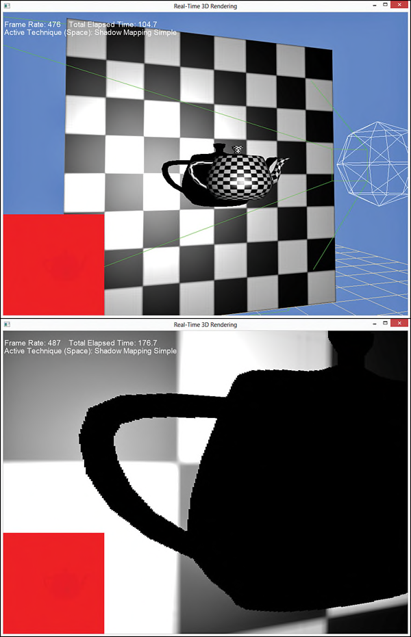
现在已经完成了实现shadow mapping所需要的所有模块。实际上,阴影映射的处理过程与投影纹理映射使用occlusion testing基本相同。首先,从光源投射的方向把场景渲染成一个depth map。然后从camera投射的方向渲染场景,并使用depth map作为输入用于确定一个object是否“位于阴影中”。列表19.8中列出了第一个shadow-mapping shader代码。列表19.8 An initial shadow-mapping shader
#include "include\\Common.fxh"

/************* Resources *************/
static const float4 ColorWhite = { 1, 1, 1, 1 };
static const float3 ColorBlack = { 0, 0, 0 };
static const float DepthBias = 0.005;

cbuffer CBufferPerFrame
{
    float4 AmbientColor = { 1.0f, 1.0f, 1.0f, 0.0f };
    float4 LightColor = { 1.0f, 1.0f, 1.0f, 1.0f };
    float3 LightPosition = { 0.0f, 0.0f, 0.0f };
    float LightRadius = 10.0f;
    float3 CameraPosition;
}

cbuffer CBufferPerObject
{
    float4x4 WorldViewProjection : WORLDVIEWPROJECTION;
    float4x4 World : WORLD;
    float4 SpecularColor : SPECULAR = { 1.0f, 1.0f, 1.0f, 1.0f };
    float SpecularPower : SPECULARPOWER  = 25.0f;

    float4x4 ProjectiveTextureMatrix;
}

Texture2D ColorTexture;
Texture2D ShadowMap;

SamplerState ShadowMapSampler
{
    Filter = MIN_MAG_MIP_POINT;
    AddressU = BORDER;
    AddressV = BORDER;
    BorderColor = ColorWhite;
};

SamplerState ColorSampler
{
    Filter = MIN_MAG_MIP_LINEAR;
    AddressU = WRAP;
    AddressV = WRAP;
};

RasterizerState BackFaceCulling
{
    CullMode = BACK;
};

/************* Data Structures *************/

struct VS_INPUT
{
    float4 ObjectPosition : POSITION;
    float2 TextureCoordinate : TEXCOORD;
    float3 Normal : NORMAL;
};

struct VS_OUTPUT
{
    float4 Position : SV_Position;
    float3 Normal : NORMAL;
    float2 TextureCoordinate : TEXCOORD0;
    float3 WorldPosition : TEXCOORD1;
    float Attenuation : TEXCOORD2;
    float4 ShadowTextureCoordinate : TEXCOORD3;
};

/************* Vertex Shader *************/

VS_OUTPUT vertex_shader(VS_INPUT IN)
{
    VS_OUTPUT OUT = (VS_OUTPUT)0;

    OUT.Position = mul(IN.ObjectPosition, WorldViewProjection);
    OUT.WorldPosition = mul(IN.ObjectPosition, World).xyz;
    OUT.TextureCoordinate = IN.TextureCoordinate;
    OUT.Normal = normalize(mul(float4(IN.Normal, 0), World).xyz);

    float3 lightDirection = LightPosition - OUT.WorldPosition;
    OUT.Attenuation = saturate(1.0f - (length(lightDirection) / LightRadius));

    OUT.ShadowTextureCoordinate = mul(IN.ObjectPosition, ProjectiveTextureMatrix);

    return OUT;
}

/************* Pixel Shaders *************/

float4 shadow_pixel_shader(VS_OUTPUT IN) : SV_Target
{
    float4 OUT = (float4)0;

    float3 lightDirection = LightPosition - IN.WorldPosition;
    lightDirection = normalize(lightDirection);

    float3 viewDirection = normalize(CameraPosition - IN.WorldPosition);

    float3 normal = normalize(IN.Normal);
    float n_dot_l = dot(normal, lightDirection);
    float3 halfVector = normalize(lightDirection + viewDirection);
    float n_dot_h = dot(normal, halfVector);

    float4 color = ColorTexture.Sample(ColorSampler, IN.TextureCoordinate);
    float4 lightCoefficients = lit(n_dot_l, n_dot_h, SpecularPower);

    float3 ambient = get_vector_color_contribution(AmbientColor, color.rgb);
    float3 diffuse = get_vector_color_contribution(LightColor, lightCoefficients.y * color.rgb) * IN.Attenuation;
    float3 specular = get_scalar_color_contribution(SpecularColor, min(lightCoefficients.z, color.w)) * IN.Attenuation;

    if (IN.ShadowTextureCoordinate.w >= 0.0f)
    {
        IN.ShadowTextureCoordinate.xyz /= IN.ShadowTextureCoordinate.w;
        float pixelDepth = IN.ShadowTextureCoordinate.z;
        float sampledDepth = ShadowMap.Sample(ShadowMapSampler, IN.ShadowTextureCoordinate.xy).x + DepthBias;

        // Shadow applied in a boolean fashion -- either in shadow or not
        float3 shadow = (pixelDepth > sampledDepth ? ColorBlack : ColorWhite.rgb);
        diffuse *= shadow;
        specular *= shadow;
    }

    OUT.rgb = ambient + diffuse + specular;
    OUT.a = 1.0f;

    return OUT;
}

/************* Techniques *************/

technique11 shadow_mapping
{
    pass p0
    {
        SetVertexShader(CompileShader(vs_5_0, vertex_shader()));
        SetGeometryShader(NULL);
        SetPixelShader(CompileShader(ps_5_0, shadow_pixel_shader()));

        SetRasterizerState(BackFaceCulling);
    }
}
该shader代码与使用occlusion testing的projective texture-mapping shader非常类似。在shadow-mapping shader中,使用变量ShadowMapyojg 表示detph map,以及对应的ShadowMapSampler。主要的修改都是在pixel shader中,首先对shadow map进行采样并加上偏移值,然后与pixel depth值进行比较。如果pixel depth大于smapled depth,表示该pixel位于阴影中,需要使用一种阴影的颜色(该示例中使用黑色)调整pixel的diffuse和specular值,尽管不调整ambient值。需要注意的是,这是一种要么全是要么全否的technique;也就是说pixel要么完全在阴影中要么完全不在阴影中。这种方法会产生如图19.7所示的hard-edged(棱角分明)阴影。
Percentage Closer Filtering
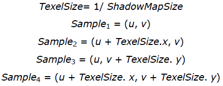
通过多次采样depth map,并使用这些采样值确定位于阴影中的采样区域范围,可以使用产生的阴影边缘更柔和(soft,与上面的hard-edge对应)。这种方法被称为percentage closer filtering(PCF)。一般情况下,PCF方法是在所需要采样的UV坐标点周围,采样一个2×2的网格所包含的4个值。然后把每一个采样值与object的pixel depth进行比较,以确定该采样值是否位于阴影中,然后对4个值进行插值计算。如果有3个采样值位于阴影中而有1个没有,就表示pixel值有75%的概率位于阴影中。其中UV坐标值是通过depth map的大小计算得到的:
列表19.9 A Shadow-Mapping Shader with Manual PCF
cbuffer CBufferPerFrame
{
    float4 AmbientColor = { 1.0f, 1.0f, 1.0f, 0.0f };
    float4 LightColor = { 1.0f, 1.0f, 1.0f, 1.0f };
    float3 LightPosition = { 0.0f, 0.0f, 0.0f };
    float LightRadius = 10.0f;
    float3 CameraPosition;
    float2 ShadowMapSize = { 1024.0f, 1024.0f };
}

float4 shadow_manual_pcf_pixel_shader(VS_OUTPUT IN) : SV_Target
{
    float4 OUT = (float4)0;

    float3 lightDirection = LightPosition - IN.WorldPosition;
    lightDirection = normalize(lightDirection);

    float3 viewDirection = normalize(CameraPosition - IN.WorldPosition);

    float3 normal = normalize(IN.Normal);
    float n_dot_l = dot(normal, lightDirection);
    float3 halfVector = normalize(lightDirection + viewDirection);
    float n_dot_h = dot(normal, halfVector);

    float4 color = ColorTexture.Sample(ColorSampler, IN.TextureCoordinate);
    float4 lightCoefficients = lit(n_dot_l, n_dot_h, SpecularPower);

    float3 ambient = get_vector_color_contribution(AmbientColor, color.rgb);
    float3 diffuse = get_vector_color_contribution(LightColor, lightCoefficients.y * color.rgb) * IN.Attenuation;
    float3 specular = get_scalar_color_contribution(SpecularColor, min(lightCoefficients.z, color.w)) * IN.Attenuation;

    if (IN.ShadowTextureCoordinate.w >= 0.0f)
    {
        IN.ShadowTextureCoordinate.xyz /= IN.ShadowTextureCoordinate.w;

        float2 texelSize = 1.0f / ShadowMapSize;
        float sampledDepth1 = ShadowMap.Sample(ShadowMapSampler, IN.ShadowTextureCoordinate.xy).x + DepthBias;
        float sampledDepth2 = ShadowMap.Sample(ShadowMapSampler, IN.ShadowTextureCoordinate.xy + float2(texelSize.x, 0)).x + DepthBias;
        float sampledDepth3 = ShadowMap.Sample(ShadowMapSampler, IN.ShadowTextureCoordinate.xy + float2(0, texelSize.y)).x + DepthBias;
        float sampledDepth4 = ShadowMap.Sample(ShadowMapSampler, IN.ShadowTextureCoordinate.xy + float2(texelSize.x, texelSize.y)).x + DepthBias;

        float pixelDepth = IN.ShadowTextureCoordinate.z;
        float shadowFactor1 = (pixelDepth > sampledDepth1 ? 0.0f : 1.0f);
        float shadowFactor2 = (pixelDepth > sampledDepth2 ? 0.0f : 1.0f);
        float shadowFactor3 = (pixelDepth > sampledDepth3 ? 0.0f : 1.0f);
        float shadowFactor4 = (pixelDepth > sampledDepth4 ? 0.0f : 1.0f);

        float2 lerpValues = frac(IN.ShadowTextureCoordinate.xy * ShadowMapSize);
        float shadow = lerp(lerp(shadowFactor1, shadowFactor2, lerpValues.x), lerp(shadowFactor3, shadowFactor4, lerpValues.x), lerpValues.y);
        diffuse *= shadow;
        specular *= shadow;
    }

    OUT.rgb = ambient + diffuse + specular;
    OUT.a = 1.0f;

    return OUT;
}
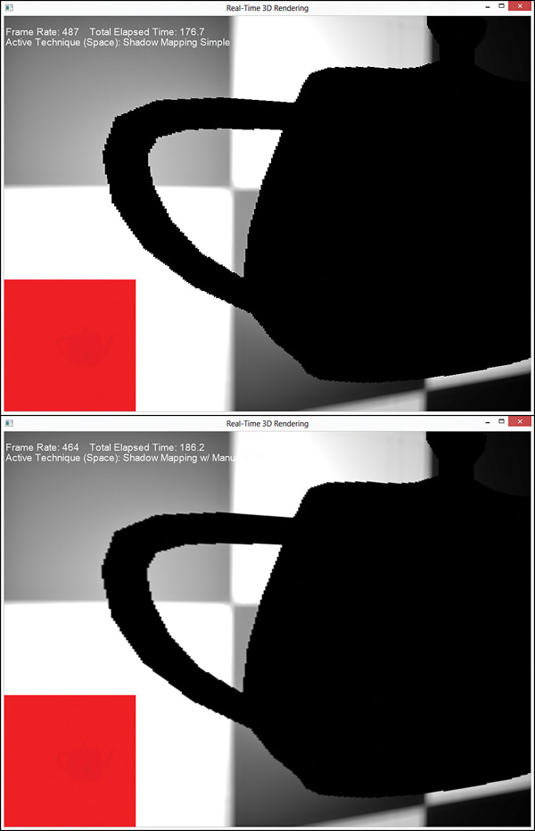
在该pixel shader中,首先采样并偏移计算4个depths值,然后使用HLSL的内置函数lerp()对4个“in-shadow factors”进行插值计算。其中,插值因子(用于插值计算的每一个源数据所占的比例)是使用HLSL的内置函数frac()计算得到的,该函数用于获取一个浮点数的小数部分。图19.8中显示了使用PCF模式下的shadow mapping与原始shadow mapping的比较结果。
重复多次采样depth mapth需要高昂的计算成本,并且采样次数越多,shader的计算成本越大。值得庆幸的是,Direct3D 11中提供了内置函数SampleCmp(),用于直接支持PCF操作,使用该函数比手动计算PCF性能更优。因此,可以使用列表19.10所示的代码重新编写之前的PCF shader。
列表19.10 A Shadow-Mapping Shader with Intrinsic PCF
SamplerComparisonState PcfShadowMapSampler
{
    Filter = COMPARISON_MIN_MAG_LINEAR_MIP_POINT;
    AddressU = BORDER;
    AddressV = BORDER;
    BorderColor = ColorWhite;
    ComparisonFunc = LESS_EQUAL;
};

float4 shadow_pcf_pixel_shader(VS_OUTPUT IN) : SV_Target
{
    float4 OUT = (float4)0;

    float3 lightDirection = LightPosition - IN.WorldPosition;
    lightDirection = normalize(lightDirection);

    float3 viewDirection = normalize(CameraPosition - IN.WorldPosition);

    float3 normal = normalize(IN.Normal);
    float n_dot_l = dot(normal, lightDirection);
    float3 halfVector = normalize(lightDirection + viewDirection);
    float n_dot_h = dot(normal, halfVector);

    float4 color = ColorTexture.Sample(ColorSampler, IN.TextureCoordinate);
    float4 lightCoefficients = lit(n_dot_l, n_dot_h, SpecularPower);

    float3 ambient = get_vector_color_contribution(AmbientColor, color.rgb);
    float3 diffuse = get_vector_color_contribution(LightColor, lightCoefficients.y * color.rgb) * IN.Attenuation;
    float3 specular = get_scalar_color_contribution(SpecularColor, min(lightCoefficients.z, color.w)) * IN.Attenuation;

    IN.ShadowTextureCoordinate.xyz /= IN.ShadowTextureCoordinate.w;
    float pixelDepth = IN.ShadowTextureCoordinate.z;

    float shadow = ShadowMap.SampleCmpLevelZero(PcfShadowMapSampler, IN.ShadowTextureCoordinate.xy, pixelDepth).x;
    diffuse *= shadow;
    specular *= shadow;

    OUT.rgb = ambient + diffuse + specular;
    OUT.a = 1.0f;

    return OUT;
}
在该shader中去掉了手动计算偏移,阴影比较以及线性插值的代码。只使用了一个SampleCmpLevelZero()函数就可以完成所有这些操作。该函数使用2×2的PCF filtering采样mip-level zero(创建depth map时唯一的mipmap级别),并把采样值与函数的第三个参数(pixel depth)进行比较。另外该函数的参数为SamplerComparisonState类型对象,而不是常用的SamplerObject类型,并使用的filter类型为COMPARISON_MIN_MAG_LINEAR_MIP_POINT。 虽然在创建depth map时需要使用一个RasterizerState对象提供depth的bias值,但是使用这种方法与手动计算PCF的输出结果一样。如果在创建depth map时设置bias值,是本章要计算的最后一个主题, slop-scaled depth biasing。
Slope-Scaled Depth Biasing
要提供一个固定的bias值用于内置的PCF filtering,需要修改DepthMap.fx shader代码,如列表19.11所示。列表19.11 Setting the Bias When Creating the Depth Map
RasterizerState DepthBias
{
	DepthBias = 84000;
};

float4 create_depthmap_vertex_shader(float4 ObjectPosition : POSITION) : SV_Position
{
    return mul(ObjectPosition, WorldLightViewProjection);
}

technique11 create_depthmap_w_bias
{
    pass p0
    {
        SetVertexShader(CompileShader(vs_5_0, create_depthmap_vertex_shader()));
        SetGeometryShader(NULL);
        SetPixelShader(NULL);
    }
}
在该shader中,RasterizerState类型对象中的DepthBias变量指定了一个固定的偏移值用于写入depth buffer中。使用如下的公式计算最终的bias值:
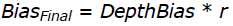
其中,r是使用depth map的浮点数格式所得表示的最小值(比如,对于一个24-bit的depth map,r = 

注意
这个计算bias值的公式是用于depth buffer为UNORM格式的情况下。关于depth buffer为浮点数格式的情况,请查看MSDN Direct3D 档中的具体计算公式。
可能你曾经想过不使用slop-scaled depth biasing方法,仅仅使用一个足够大的固定bias值用于满足大部分的geometry。但是,使用一个过大的bias值会产生一种称为 peter panning的效果,perter panning是指阴影看起来与对应的ojbect分开了(该名称来自于儿童图书小飞侠,小飞侠的影子与身体分离了)。而且这些值是与具体的场景相关的,针对不同的场景需要尝试找到最优的值。本书的配套网站提供了一个示例,支持动态调整这些值,并显示修改的结果。
总结
本章,主要讲述了一种产生阴影的常用技术,shadow mapping。作为高级渲染主题的一部分,我们编写了projective texture mapping shaders,这是一种把一个2D纹理投影到任意形状几何体上的技术。在此过程中,我们学习了如何创建depth maps和occlusion testing,并使用这些maps实现了一个shadow mapping shader。另外,讨论了在实现shadow mapping过程中遇到的各种问题,包括shadow acne,hard edges以及peter panning,并研究了解决这些问题的方法。Shadow mapping并不是用于产生阴影的唯一方法,还有很多其他的技术可以用于解决阴影的残影问题。特别是研究 cascaded shadow maps和 variance shadow maps。在MSDN上,微软提供了一篇关于阴影的非常好的文章“Common Techniques to Improve Shadow Depth Maps”。本书的配套网站上提供了该文章的链接。
Exercises
1. Experiment with all the effects and demo applications from this chapter. Vary the shader inputs, and observe the results.2. Vary the size of your depth/shadow map, and observe the results. The ShadowMappingDemo application (available on the companion website) uses a 1024×1024 depth map. What happens when you go to 2048×2048 or 4096×4096? What about 256×256?
3. While perspective projection (what we’ve used for the projector in this chapter) is common for simulating shadows for point and spotlights, directional light shadows are typically implemented through orthographic projection. Implement an orthographic projector and integrate it with your shadow-mapping shader.
1、测试本章所有的effects和示例程序。尝试使用各种不同的shader输入数据,并观察输出结果。
2、尝试使用不同尺寸的depth/shadow map,并观察结果。ShadowMappingDemo示例程序中(见本书配套网站)使用了一个1024×1024的depth map。尝试使用2048×2048或者4096×4096,并观察输出结果,如果使用256×256又会是什么情况?
3、模拟point light和spotlights照射的阴影通常使用透视投影(本章所使用的projector),而对于directional light阴影则是使用正交投影实现的。实现一个正交投影的projector,并集成到shadow-mapping shader中。


 879
879


 被折叠的 条评论
为什么被折叠?
被折叠的 条评论
为什么被折叠?
 到【灌水乐园】发言


