


前面几章分析了Codec、Platform、Machine驱动的组成部分及其注册过程,这三者都是物理设备相关的,大家应该对音频物理链路有了一定的认知。接着分析音频驱动的中间层,由于这些并不是真正的物理设备,故我们称之为逻辑设备。
PCM逻辑设备,我们又习惯称之为PCM中间层或pcm native,起着承上启下的作用:往上是与用户态接口的交互,实现音频数据在用户态和内核态之间的拷贝;往下是触发codec、platform、machine的操作函数,实现音频数据在dma_buffer<-> cpu_dai <-> codec之间的传输。
后面章节将会对这个过程详细分析,这里还是先从声卡的注册谈起。
声卡驱动中,一般挂载着多个逻辑设备,看看我们计算机的声卡驱动有几个逻辑设备:
$ cat /proc/asound/devices
  1:        : sequencer
  2: [ 0- 7]: digital audio playback
  3: [ 0- 3]: digital audio playback
  4: [ 0- 2]: digital audio capture
  5: [ 0- 0]: digital audio playback
  6: [ 0- 0]: digital audio capture
  7: [ 0- 3]: hardware dependent
  8: [ 0- 0]: hardware dependent
  9: [ 0]   : control
 33:        : timer
· digital audio playback:用于回放的PCM设备
· digital audio capture:用于录制的PCM设备
· control:用于声卡控制的CTL设备,如通路控制、音量调整等
· timer:定时器设备
· sequencer:音序器设备
嵌入式系统中,通常我们更关心PCM和CTL这两种设备。
设备节点如下:
$ ll /dev/snd
drwxr-xr-x   3 root root      260 Feb 26 13:59 ./
drwxr-xr-x  16 root root     4300 Mar  6 17:07 ../
drwxr-xr-x   2 root root       60 Feb 26 13:59 by-path/
crw-rw---T+  1 root audio 116,  9 Feb 26 13:59 controlC0
crw-rw---T+  1 root audio 116,  8 Feb 26 13:59 hwC0D0
crw-rw---T+  1 root audio 116,  7 Feb 26 13:59 hwC0D3
crw-rw---T+  1 root audio 116,  6 Feb 26 13:59 pcmC0D0c
crw-rw---T+  1 root audio 116,  5 Mar  6 19:08 pcmC0D0p
crw-rw---T+  1 root audio 116,  4 Feb 26 13:59 pcmC0D2c
crw-rw---T+  1 root audio 116,  3 Feb 26 13:59 pcmC0D3p
crw-rw---T+  1 root audio 116,  2 Feb 26 13:59 pcmC0D7p
crw-rw---T+  1 root audio 116,  1 Feb 26 13:59 seq
crw-rw---T+  1 root audio 116, 33 Feb 26 13:59 timer
可以看到这些设备节点的Major=116,Minor则与/proc/asound/devices所列的对应起来,都是字符设备。上层可以通过open/close/read/write/ioctl等系统调用来操作声卡设备,和其他字符设备类似,但一般情况下我们使用已封装好的用户接口库如tinyalsa、alsa-lib。
6.1. 声卡结构概述
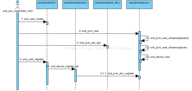
回顾下ASoC是如何注册声卡的,详细请参考章节5.ASoC machine driver,这里仅简单陈述下:
· Machine驱动初始化时,name="soc-audio"的platform_device与platform_driver匹配成功,触发soc_probe()调用;
· 继而调用snd_soc_register_card(),该函数做的事情很多:
1. 为每个音频物理链路找到对应的codec、codec_dai、cpu_dai、platform设备实例,完成dai_link的绑定;
2. 调用snd_card_create()创建声卡;
3. 依次回调cpu_dai、codec、platform的probe()函数,完成物理设备的初始化;
· 随后调用soc_new_pcm()创建pcm逻辑设备:
1. 设置pcm native中要使用的pcm操作函数,这些函数用于操作音频物理设备,包括machine、codec_dai、cpu_dai、platform;
2. 调用snd_pcm_new()创建pcm设备,回放子流实例和录制子流实例都在这里创建;
3. 回调platform驱动的pcm_new(),完成音频dma设备初始化和dma buffer内存分配;
· 最后调用snd_card_register()注册声卡。
关于音频物理设备部分(Codec/Platform/Machine)不再累述,下面详细分析声卡和PCM逻辑设备的注册过程。
上面提到声卡驱动上挂着多个逻辑子设备,有pcm(音频数据流)、control(混音器控制)、midi(迷笛)、timer(定时器)、sequencer(音序器)等。
                  +-----------+
                  | snd_card  |
                  +-----------+
                    |   |   |
        +-----------+   |   +------------+
        |               |                |
 +-----------+    +-----------+    +-----------+
 |  snd_pcm  |    |snd_control|    | snd_timer |    ...
 +-----------+    +-----------+    +-----------+
这些与声音相关的逻辑设备都在结构体snd_card管理之下,可以说snd_card是alsa中最顶层的结构。
我们再看看alsa声卡驱动的大致结构图(不是严格的UML类图,有结构体定义、模块关系、函数调用,方便标示结构模块的层次及关系):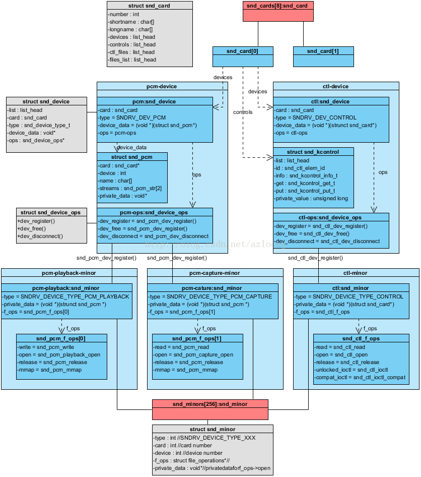
snd_cards:记录着所注册的声卡实例,每个声卡实例有着各自的逻辑设备,如PCM设备、CTL设备、MIDI设备等,并一一记录到snd_card的devices链表上。
snd_minors:记录着所有逻辑设备的上下文信息,它是声卡逻辑设备与系统调用API之间的桥梁;每个snd_minor在逻辑设备注册时被填充,在逻辑设备使用时就可以从该结构体中得到相应的信息(主要是系统调用函数集file_operations)。
6.2. 声卡的创建
声卡实例通过函数snd_card_create()来创建,其函数原型:
/**
 *  snd_card_create - create and initialize a soundcard structure
 *  @idx: card index (address) [0 ... (SNDRV_CARDS-1)]
 *  @xid: card identification (ASCII string)
 *  @module: top level module for locking
 *  @extra_size: allocate this extra size after the main soundcard structure
 *  @card_ret: the pointer to store the created card instance
 *
 *  Creates and initializes a soundcard structure.
 *
 *  The function allocates snd_card instance via kzalloc with the given
 *  space for the driver to use freely.  The allocated struct is stored
 *  in the given card_ret pointer.
 *
 *  Returns zero if successful or a negative error code.
 */
int snd_card_create(int idx, const char *xid,
            struct module *module, int extra_size,
            struct snd_card **card_ret)
注释非常详细,简单说下:
· idx:声卡的编号,如为-1,则由系统自动分配
· xid:声卡标识符,如为NULL,则以snd_card的shortname或longname代替
· card_ret:返回所创建的声卡实例的指针
如下是我的计算机的声卡信息:
$ cat /proc/asound/cards
 0 [PCH            ]: HDA-Intel - HDA Intel PCH
HDA Intel PCH at 0xf7c30000 irq 47编号number:0
标识符id:PCH
shortname:HDAIntel PCH
longname:HDAIntel PCH at 0xf7c30000 irq 47
shortname、longname常用于打印信息,上面的声卡信息是通过如下函数打印出来的:static void snd_card_info_read(struct snd_info_entry *entry,
struct snd_info_buffer *buffer)
{
int idx, count;
struct snd_card *card;
for (idx = count = 0; idx < SNDRV_CARDS; idx++) {
mutex_lock(&snd_card_mutex);
if ((card = snd_cards[idx]) != NULL) {
count++;
snd_iprintf(buffer, "%2i [%-15s]: %s - %s\n",
idx,
card->id,
card->driver,
card->shortname);
snd_iprintf(buffer, " %s\n",
card->longname);
}
mutex_unlock(&snd_card_mutex);
}
if (!count)
snd_iprintf(buffer, "--- no soundcards ---\n");
}
6.3. 逻辑设备的创建
当声卡实例建立后,接着可以创建声卡下面的各个逻辑设备了。每个逻辑设备创建时,都会调用snd_device_new()生成一个snd_device实例,并把该实例挂到声卡snd_card的devices链表上。
alsa驱动为各种逻辑设备提供了创建接口,如下:
| PCM | snd_pcm_new() |
| CONTROL | snd_ctl_create() |
| MIDI | snd_rawmidi_new() |
| TIMER | snd_timer_new() |
| SEQUENCER | snd_seq_device_new() |
| JACK | snd_jack_new() |
这些接口的一般过程如下:
int snd_xxx_new()
{
    // 这些接口供逻辑设备注册时回调
    static struct snd_device_ops ops = {
        .dev_free = snd_xxx_dev_free,
        .dev_register = snd_xxx_dev_register,
        .dev_disconnect = snd_xxx_dev_disconnect,
    };

    // 逻辑设备实例初始化

    // 新建一个设备实例snd_device,挂到snd_card的devices链表上,把该逻辑设备纳入声卡的管理当中
    return snd_device_new(card, SNDRV_DEV_xxx, card, &ops);
}
其中snd_device_ops是声卡逻辑设备的注册相关函数集,dev_register()回调尤其重要,它在声卡注册时被调用,用于建立系统的设备文件节点,/dev/snd/目录的设备文件节点都是在这里创建的。
例如snd_ctl_dev_register():
// CTL设备的系统调用接口
static const struct file_operations snd_ctl_f_ops =
{
    .owner =    THIS_MODULE,
    .read =     snd_ctl_read,
    .open =     snd_ctl_open,
    .release =  snd_ctl_release,
    .llseek =   no_llseek,
    .poll =     snd_ctl_poll,
    .unlocked_ioctl =   snd_ctl_ioctl,
    .compat_ioctl = snd_ctl_ioctl_compat,
    .fasync =   snd_ctl_fasync,
};

/*
 * registration of the control device
 */
static int snd_ctl_dev_register(struct snd_device *device)
{
    struct snd_card *card = device->device_data;
    int err, cardnum;
    char name[16];

    if (snd_BUG_ON(!card))
        return -ENXIO;
    cardnum = card->number;
    if (snd_BUG_ON(cardnum < 0 || cardnum >= SNDRV_CARDS))
        return -ENXIO;
    sprintf(name, "controlC%i", cardnum);
    if ((err = snd_register_device(SNDRV_DEVICE_TYPE_CONTROL, card, -1,
                       &snd_ctl_f_ops, card, name)) < 0)
        return err;
    return 0;
}
事实是调用snd_register_device_for_dev():
· 分配并初始化一个snd_minor实例;
· 保存该snd_minor实例到snd_minors数组中;
· 调用device_create()生成设备文件节点。/**
* snd_register_device_for_dev - Register the ALSA device file for the card
* @type: the device type, SNDRV_DEVICE_TYPE_XXX
* @card: the card instance
* @dev: the device index
* @f_ops: the file operations
* @private_data: user pointer for f_ops->open()
* @name: the device file name
* @device: the &struct device to link this new device to
*
* Registers an ALSA device file for the given card.
* The operators have to be set in reg parameter.
*
* Returns zero if successful, or a negative error code on failure.
*/
int snd_register_device_for_dev(int type, struct snd_card *card, int dev,
const struct file_operations *f_ops,
void *private_data,
const char *name, struct device *device)
{
int minor;
struct snd_minor *preg;
if (snd_BUG_ON(!name))
return -EINVAL;
preg = kmalloc(sizeof *preg, GFP_KERNEL);
if (preg == NULL)
return -ENOMEM;
preg->type = type;
preg->card = card ? card->number : -1;
preg->device = dev;
preg->f_ops = f_ops;
preg->private_data = private_data;
mutex_lock(&sound_mutex);
#ifdef CONFIG_SND_DYNAMIC_MINORS
minor = snd_find_free_minor(type);
#else
minor = snd_kernel_minor(type, card, dev);
if (minor >= 0 && snd_minors[minor])
minor = -EBUSY;
#endif
if (minor < 0) {
mutex_unlock(&sound_mutex);
kfree(preg);
return minor;
}
snd_minors[minor] = preg;
preg->dev = device_create(sound_class, device, MKDEV(major, minor),
private_data, "%s", name);
if (IS_ERR(preg->dev)) {
snd_minors[minor] = NULL;
mutex_unlock(&sound_mutex);
minor = PTR_ERR(preg->dev);
kfree(preg);
return minor;
}
mutex_unlock(&sound_mutex);
return 0;
}上面过程是声卡注册时才被回调的。
6.4. 声卡的注册
当声卡下的所有逻辑设备都已经准备就绪后,就可以调用snd_card_register()注册声卡了:
· 创建声卡的sysfs设备;
· 调用snd_device_register_all()注册所有挂在该声卡下的逻辑设备;
· 建立proc信息文件和sysfs属性文件。/**
* snd_card_register - register the soundcard
* @card: soundcard structure
*
* This function registers all the devices assigned to the soundcard.
* Until calling this, the ALSA control interface is blocked from the
* external accesses. Thus, you should call this function at the end
* of the initialization of the card.
*
* Returns zero otherwise a negative error code if the registration failed.
*/
int snd_card_register(struct snd_card *card)
{
int err;
if (snd_BUG_ON(!card))
return -EINVAL;
// 创建sysfs设备,声卡的class将会出现在/sys/class/sound/下面
if (!card->card_dev) {
card->card_dev = device_create(sound_class, card->dev,
MKDEV(0, 0), card,
"card%i", card->number);
if (IS_ERR(card->card_dev))
card->card_dev = NULL;
}
// 遍历挂在该声卡的所有逻辑设备,回调各snd_device的ops->dev_register()完成各逻辑设备的注册
if ((err = snd_device_register_all(card)) < 0)
return err;
mutex_lock(&snd_card_mutex);
if (snd_cards[card->number]) {
/* already registered */
mutex_unlock(&snd_card_mutex);
return 0;
}
if (*card->id) {
/* make a unique id name from the given string */
char tmpid[sizeof(card->id)];
memcpy(tmpid, card->id, sizeof(card->id));
snd_card_set_id_no_lock(card, tmpid, tmpid);
} else {
/* create an id from either shortname or longname */
const char *src;
src = *card->shortname ? card->shortname : card->longname;
snd_card_set_id_no_lock(card, src,
retrieve_id_from_card_name(src));
}
snd_cards[card->number] = card; // 把该声卡实例保存到snd_cards数组中
mutex_unlock(&snd_card_mutex);
// 声卡相关信息,见:/proc/asound/card0
init_info_for_card(card);
#if defined(CONFIG_SND_MIXER_OSS) || defined(CONFIG_SND_MIXER_OSS_MODULE)
if (snd_mixer_oss_notify_callback)
snd_mixer_oss_notify_callback(card, SND_MIXER_OSS_NOTIFY_REGISTER);
#endif
// 声卡的sysfs属性节点
if (card->card_dev) {
err = device_create_file(card->card_dev, &card_id_attrs);
if (err < 0)
return err;
err = device_create_file(card->card_dev, &card_number_attrs);
if (err < 0)
return err;
}
return 0;
}至此完成了声卡及声卡下的所有逻辑设备的注册,用户态应用可以通过系统调用来访问这些设备了。
6.5. PCM设备的创建
最后我们简单说说PCM设备的建立过程:
snd_pcm_set_ops:设置PCM设备的操作接口,设置完成后,PCM设备就可以控制/操作底层音频物理设备了。
snd_pcm_new:
· 创建一个PCM设备实例snd_pcm;
· 创建playback stream和capture stream,旗下的substream也同时建立;
· 调用snd_device_new()把PCM设备挂到声卡的devices链表上。static int _snd_pcm_new(struct snd_card *card, const char *id, int device,
int playback_count, int capture_count, bool internal,
struct snd_pcm **rpcm)
{
struct snd_pcm *pcm;
int err;
static struct snd_device_ops ops = {
.dev_free = snd_pcm_dev_free,
.dev_register = snd_pcm_dev_register,
.dev_disconnect = snd_pcm_dev_disconnect,
};
if (snd_BUG_ON(!card))
return -ENXIO;
if (rpcm)
*rpcm = NULL;
pcm = kzalloc(sizeof(*pcm), GFP_KERNEL);
if (pcm == NULL) {
snd_printk(KERN_ERR "Cannot allocate PCM\n");
return -ENOMEM;
}
pcm->card = card;
pcm->device = device;
pcm->internal = internal;
if (id)
strlcpy(pcm->id, id, sizeof(pcm->id));
if ((err = snd_pcm_new_stream(pcm, SNDRV_PCM_STREAM_PLAYBACK, playback_count)) < 0) {
snd_pcm_free(pcm);
return err;
}
if ((err = snd_pcm_new_stream(pcm, SNDRV_PCM_STREAM_CAPTURE, capture_count)) < 0) {
snd_pcm_free(pcm);
return err;
}
mutex_init(&pcm->open_mutex);
init_waitqueue_head(&pcm->open_wait);
if ((err = snd_device_new(card, SNDRV_DEV_PCM, pcm, &ops)) < 0) {
snd_pcm_free(pcm);
return err;
}
if (rpcm)
*rpcm = pcm;
return 0;
}我们再看看PCM设备的系统调用接口:
const struct file_operations snd_pcm_f_ops[2] = {
    {
        .owner =        THIS_MODULE,
        .write =        snd_pcm_write,
        .aio_write =        snd_pcm_aio_write,
        .open =         snd_pcm_playback_open,
        .release =      snd_pcm_release,
        .llseek =       no_llseek,
        .poll =         snd_pcm_playback_poll,
        .unlocked_ioctl =   snd_pcm_playback_ioctl,
        .compat_ioctl =     snd_pcm_ioctl_compat,
        .mmap =         snd_pcm_mmap,
        .fasync =       snd_pcm_fasync,
        .get_unmapped_area =    snd_pcm_get_unmapped_area,
    },
    {
        .owner =        THIS_MODULE,
        .read =         snd_pcm_read,
        .aio_read =     snd_pcm_aio_read,
        .open =         snd_pcm_capture_open,
        .release =      snd_pcm_release,
        .llseek =       no_llseek,
        .poll =         snd_pcm_capture_poll,
        .unlocked_ioctl =   snd_pcm_capture_ioctl,
        .compat_ioctl =     snd_pcm_ioctl_compat,
        .mmap =         snd_pcm_mmap,
        .fasync =       snd_pcm_fasync,
        .get_unmapped_area =    snd_pcm_get_unmapped_area,
    }
};
snd_pcm_f_ops作为snd_register_device_for_dev()的参数被传入,并被记录在snd_minors[minor]中的字段f_ops中。snd_pcm_f_ops[0]是回放使用的系统调用接口,snd_pcm_f_ops[1]是录制使用的系统调用接口。
6.6. 参考资料
· Linux ALSA声卡驱动之二:声卡的创建:http://blog.csdn.net/droidphone/article/details/6289712
· Linux ALSA声卡驱动之三:PCM设备的创建:http://blog.csdn.net/droidphone/article/details/6308006


 677
677


 被折叠的 条评论
为什么被折叠?
被折叠的 条评论
为什么被折叠?
 到【灌水乐园】发言


