


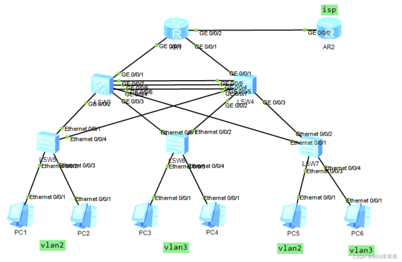
搭建实验拓扑图
实验开始
配置r1,r2的IP地址及环回
r1
[r1]interface LoopBack 0
[r1-LoopBack0]ip address 1.1.1.1 32
[r1]interface g0/0/0
[r1-GigabitEthernet0/0/0]ip address 23.1.1.1 24
[r1]interface g0/0/1
[r1-GigabitEthernet0/0/1]ip address 34.1.1.1 24
[r1]interface g0/0/2
[r1-GigabitEthernet0/0/2]ip address 12.1.1.1 24
r2
[r2]interface LoopBack 0
[r2-LoopBack0]ip address 2.2.2.2 32
[r2]interface g0/0/0
[r2-GigabitEthernet0/0/0]ip address 12.1.1.2 24
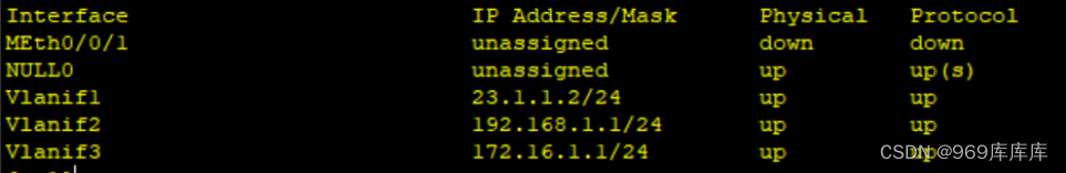
在sw1的vlanif 1 上配地址
[sw1]interface vlanif 1
[sw1-Vlanif1]ip address 23.1.1.2 24
并且ping 23.1.1.1可以ping通
[sw1]ping 23.1.1.1
PING 23.1.1.1: 56 data bytes, press CTRL_C to break
Reply from 23.1.1.1: bytes=56 Sequence=1 ttl=255 time=90 ms
Reply from 23.1.1.1: bytes=56 Sequence=2 ttl=255 time=20 ms
Reply from 23.1.1.1: bytes=56 Sequence=3 ttl=255 time=30 ms
Reply from 23.1.1.1: bytes=56 Sequence=4 ttl=255 time=50 ms
Reply from 23.1.1.1: bytes=56 Sequence=5 ttl=255 time=30 ms
--- 23.1.1.1 ping statistics ---
5 packet(s) transmitted
5 packet(s) received
0.00% packet loss
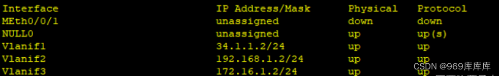
round-trip min/avg/max = 20/44/90 ms给sw2配地址
[sw2]interface vlanif 1
[sw2-Vlanif1]ip address 34.1.1.2 24
在sw1上做汇总
[sw1]interface Eth-Trunk 1
[sw1-Eth-Trunk1]q
[sw1]interface g0/0/2
[sw1-GigabitEthernet0/0/2]eth-trunk 1
[sw1-GigabitEthernet0/0/2]q
[sw1]interface g0/0/3
[sw1-GigabitEthernet0/0/3]eth-trunk 1
[sw1-GigabitEthernet0/0/3]q
[sw1]interface g0/0/7
[sw1-GigabitEthernet0/0/7]eth-trunk 1
在sw2上做汇总
[sw2]interface Eth-Trunk 1
[sw2-Eth-Trunk1]q
[sw2]interface g0/0/2
[sw2-GigabitEthernet0/0/2]eth-trunk 1
[sw2-GigabitEthernet0/0/2]q
[sw2]interface g0/0/3
[sw2-GigabitEthernet0/0/3]eth-trunk 1
[sw2-GigabitEthernet0/0/3]q
[sw2]interface g0/0/7
[sw2-GigabitEthernet0/0/7]eth-trunk 1
在sw1上启动
[sw1]interface Eth-Trunk 1
[sw1-Eth-Trunk1]port link-type trunk
[sw1-Eth-Trunk1]port trunk allow-pass vlan all
在sw2上启动
[sw2]interface Eth-Trunk 1
[sw2-Eth-Trunk1]port link-type trunk
[sw2-Eth-Trunk1]port trunk allow-pass vlan all
在sw1上启动vlan
[sw1]vlan batch 2 3在sw2上启动vlan
[sw2]vlan batch 2 3在sw1上给接口配置vlan
[sw1]interface g0/0/4
[sw1-GigabitEthernet0/0/4]port link-type access
[sw1-GigabitEthernet0/0/4]port default vlan 2
[sw1-GigabitEthernet0/0/4]q
[sw1]interface g0/0/5
[sw1-GigabitEthernet0/0/5]port link-type access
[sw1-GigabitEthernet0/0/5]port default vlan 3
[sw1-GigabitEthernet0/0/5]q
[sw1]interface g0/0/6
[sw1-GigabitEthernet0/0/6]port link-type trunk
[sw1-GigabitEthernet0/0/6]port trunk allow-pass vlan all
在sw2上给接口配置vlan
[sw2]interface g0/0/6
[sw2-GigabitEthernet0/0/6]port link-type trunk
[sw2-GigabitEthernet0/0/6]port trunk allow-pass vlan all
[sw2-GigabitEthernet0/0/6]q
[sw2]interface g0/0/4
[sw2-GigabitEthernet0/0/4]port link-type access
[sw2-GigabitEthernet0/0/4]port default vlan 2
[sw2]interface g0/0/5
[sw2-GigabitEthernet0/0/5]port link-type access
[sw2-GigabitEthernet0/0/5]port default vlan 3
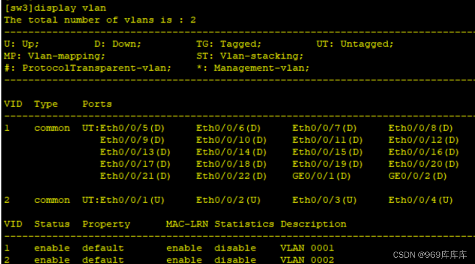
在sw3上划分vlan
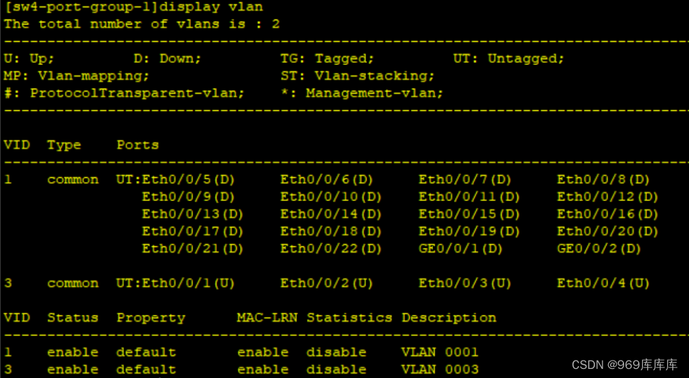
在sw4上划分vlan
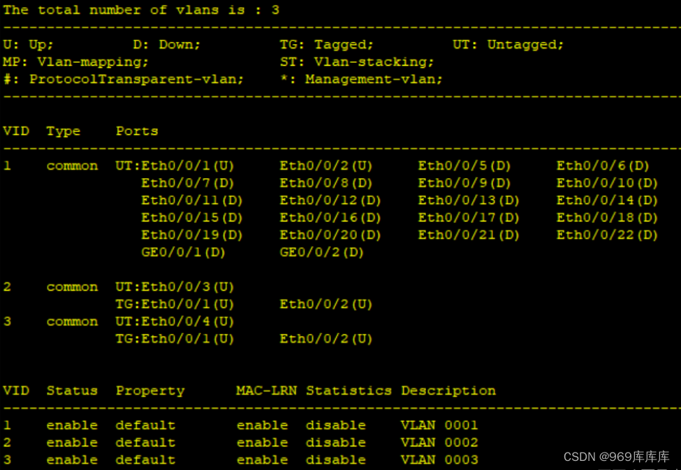
在sw5上划分vlan
在sw1上做stp
[sw1]stp mode mstp
[sw1]stp region-configuration
[sw1-mst-region]instance 1 vlan 2
[sw1-mst-region]instance 2 vlan 3
[sw1-mst-region]active region-configuration
[sw1]stp instance 1 root primary
[sw1]stp instance 2 root secondary
在sw2做stp
[sw2]stp mode mstp
[sw2]stp region-configuration
[sw2-mst-region]instance 1 vlan 2
[sw2-mst-region]instance 2 vlan 3
[sw2-mst-region]active region-configuration
[sw2]stp instance 1 root secondary
[sw2]stp instance 2 root primary
在r1上进行ospf并下发缺省
[r1]ospf 1 router-id 1.1.1.1
[r1-ospf-1]area 0
[r1-ospf-1-area-0.0.0.0]network 23.1.1.1 0.0.0.0
[r1-ospf-1-area-0.0.0.0]network 34.1.1.1 0.0.0.0
[r1-ospf-1-area-0.0.0.0]network 1.1.1.1 0.0.0.0
[r1-ospf-1]default-route-advertise
[r1]ip route-static 0.0.0.0 0 12.1.1.2
在sw1上进行宣告
[sw1]ospf 1 router-id 2.2.2.2
[sw1-ospf-1]area 0
[sw1-ospf-1-area-0.0.0.0]network 0.0.0.0 255.255.255.255
在sw2上进行宣告
[sw2]ospf 1 router-id 3.3.3.3
[sw2-ospf-1]area 0
[sw2-ospf-1-area-0.0.0.0]network 0.0.0.0 255.255.255.255
配置sw1
配置sw2
在sw1上改ip
[sw1]interface Vlanif 3
[sw1-Vlanif3]vrrp vrid 2 virtual-ip 172.16.1.2
在sw2上改ip
[sw2]interface Vlanif 2
[sw2-Vlanif2]vrrp vrid 1 virtual-ip 192.168.1.1
[sw2]interface Vlanif 3
[sw2-Vlanif3]vrrp vrid 2 virtual-ip 172.16.1.2
在sw2上配置延迟和优先级
[sw2-Vlanif3]vrrp vrid 2 priority 120
[sw2-Vlanif3]vrrp vrid 2 preempt-mode timer delay 20
在sw1上进行dhcp
[sw1]dhcp enable
[sw1]ip pool 1
[sw1-ip-pool-1]network 192.168.1.0 mask 24
[sw1-ip-pool-1]gateway-list 192.168.1.1
[sw1-ip-pool-1]dns-list 8.8.8.8
[sw1-ip-pool-2]network 172.16.1.0 mask 24
[sw1-ip-pool-2]gateway-list 172.16.1.2
[sw1-ip-pool-2]dns-list 8.8.8.8
在sw1上进行调用
[sw1]interface Vlanif 2
[sw1-Vlanif2]dhcp select global
[sw1]interface Vlanif 3
[sw1-Vlanif3]dhcp select global
在sw2上进行dhcp
[sw2]dhcp enable
[sw2]ip pool 1
[sw2-ip-pool-1]network 192.168.1.0 mask 24
[sw2-ip-pool-1]gateway-list 192.168.1.1
[sw2-ip-pool-1]dns-list 8.8.8.8
[sw2]ip pool 3
[sw2-ip-pool-3]network 172.16.1.0 mask 24
[sw2-ip-pool-3]gateway-list 172.16.1.2
[sw2-ip-pool-3]dns-list 8.8.8.8
在sw2上进行调用
[sw2]interface Vlanif 2
[sw2-Vlanif2]dhcp select global
[sw2]interface Vlanif 3
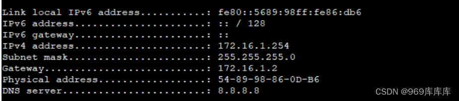
[sw2-Vlanif3]dhcp select global将pc1-pc6配置更改为dhcp
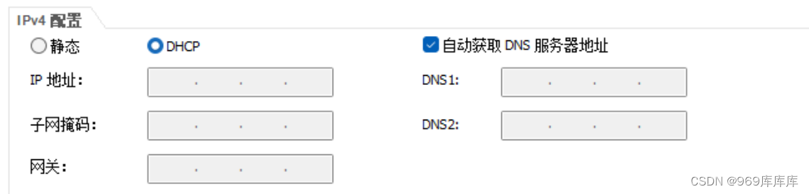
查看一下pc1-pc6的地址
 在r1上做nat
[r1]acl 2000
[r1-acl-basic-2000]rule permit source any
[r1]interface g0/0/2
[r1-GigabitEthernet0/0/2]nat outbound 2000
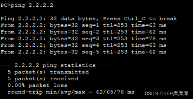
在pc1上ping 2.2.2.2可通


 310
310


 被折叠的 条评论
为什么被折叠?
被折叠的 条评论
为什么被折叠?
 到【灌水乐园】发言


