


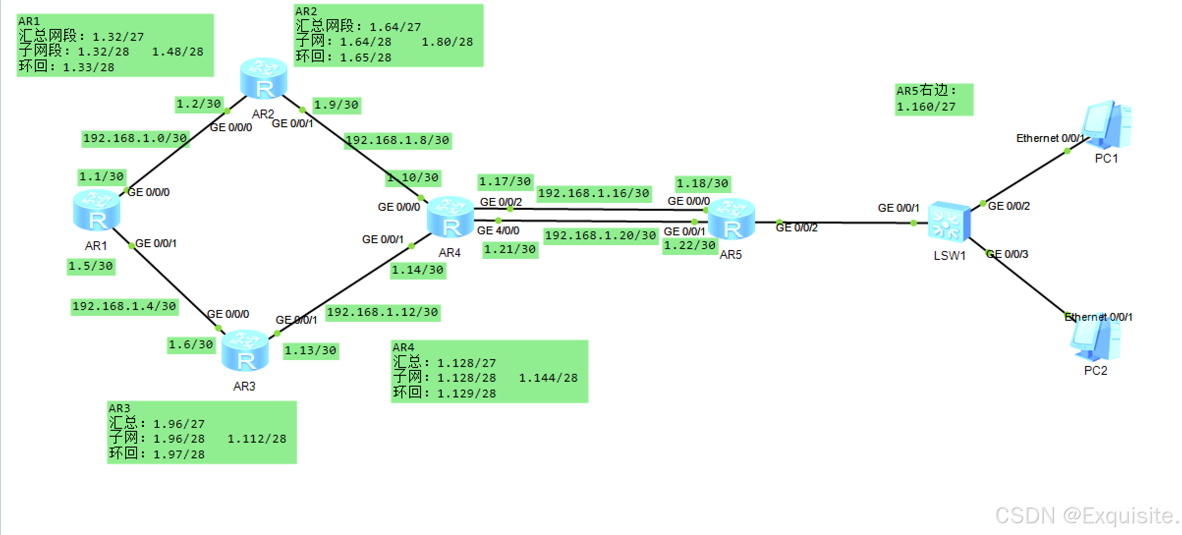
一、拓补图
二、需求
1.整张网络使用192.168.1.0/24网段进行划分
2、R1、R2、R3、R4均有两个环回来模拟用户网段
3、R5使用DHCP为PC分配IP地址
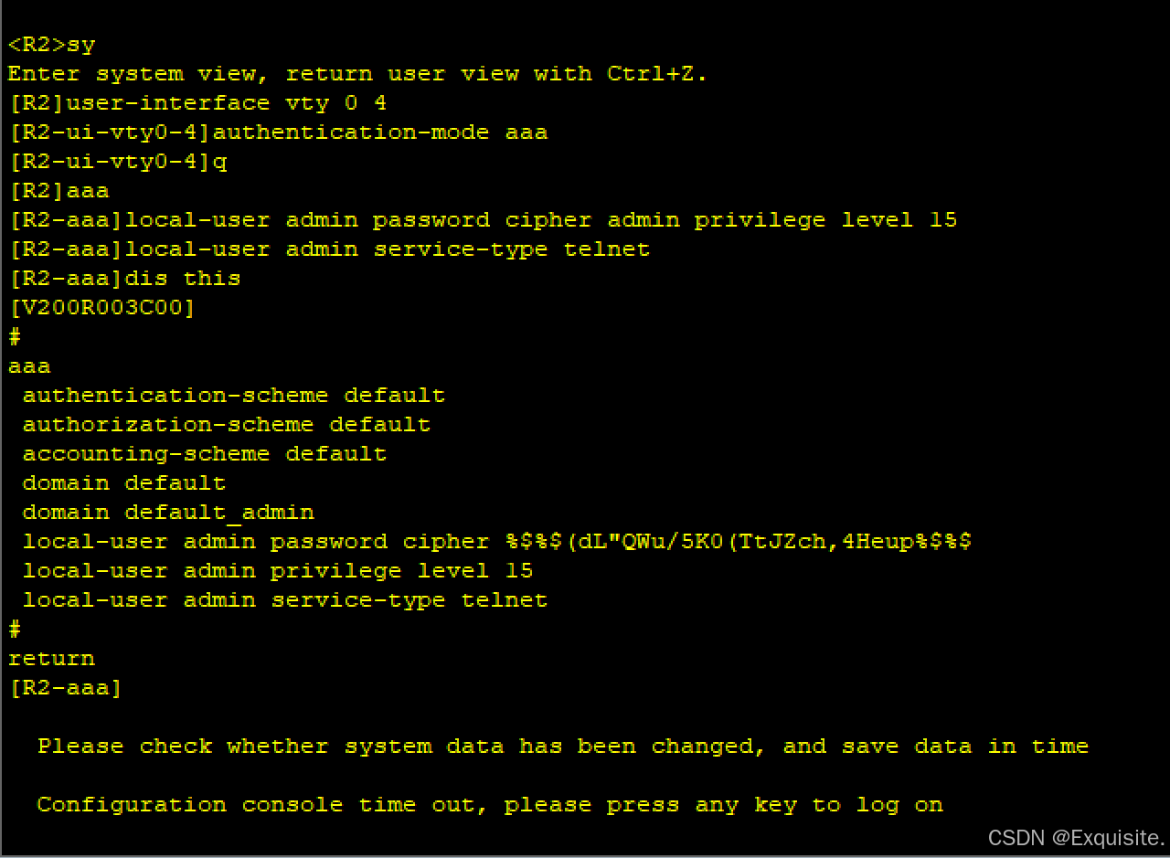
4、R2、R3、R4、R5开启Telnet功能,账号密码:admin/admin
5、使用R1进行Telnet测试登录其他设备
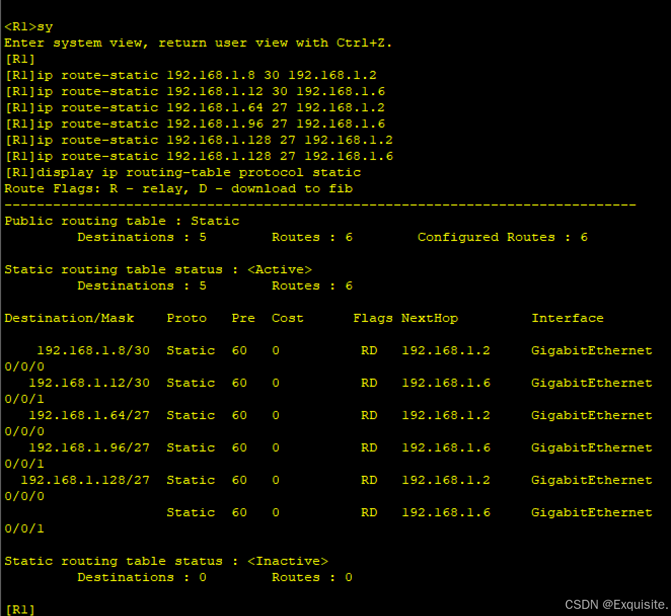
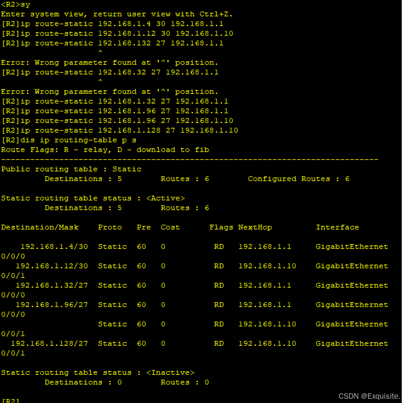
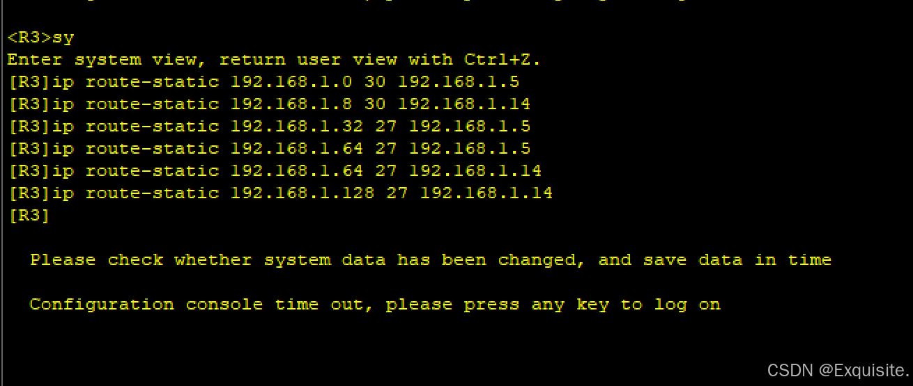
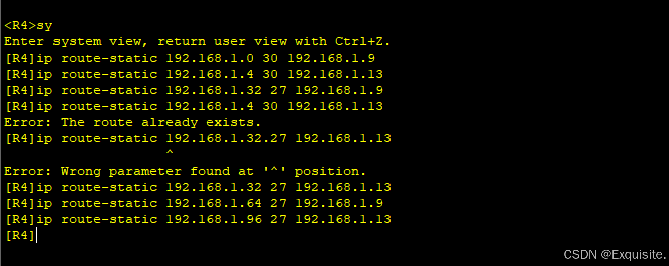
6、完成所有路由器的静态路由配置,要求使用最简化路由表的方式
7、全网可达
三、需求分析与配置
1.划分网段
拓补图中需要15个网段,需要6个骨干网段,需借3位;需要6个/30网段
192.168.1.0/24
192.168.1.000 00000 -----192.168.1.0/27 ---骨干链路
192.168.1.000 000 00 ---192.168.1.0/30 --可用ip --192.168.1.1-192.168.1.2
192.168.1.000 000 00
192.168.1.000 000 01
192.168.1.000 000 10
192.168.1.000 000 11
192.168.1.000 001 00 ---192.168.1.4/30 --192.168.1.5-192.168.1.6
192.168.1.000 010 00 ---192.168.1.8/30 --192.168.1.9-192.168.1.10
192.168.1.000 011 00 ---192.168.1.12/30 --192.168.1.13-192.168.1.14
192.168.1.000 100 00 ---192.168.1.16/30 --192.168.1.17-192.168.1.18
192.168.1.000 101 00 ---192.168.1.20/30 --192.168.1.21-192.168.1.22
192.168.1.000 110 00 ---192.168.1.24/30
192.168.1.000 111 00 ---192.168.1.28/30
192.168.1.001 00000 -----192.168.1.32/27 ---R1环回
192.168.1.001 0 0000 --192.168.1.32/28
192.168.1.001 1 0000 --192.168.1.48/28
192.168.1.010 00000 -----192.168.1.64/27 ---R2环回
192.168.1.010 0 0000 --192.168.1.64/28
192.168.1.010 1 0000 --192.168.1.80/28
192.168.1.011 00000 -----192.168.1.96/27 ---R3环回
192.168.1.011 0 0000 --192.168.1.96/28
192.168.1.011 1 0000 --192.168.1.112/28
192.168.1.100 00000 -----192.168.1.128/27 ---R4环回
192.168.1.100 0 0000 --192.168.1.128/28
192.168.1.100 1 0000 --192.168.1.144/28
192.168.1.101 00000 -----192.168.1.160/27 ---R5网段
192.168.1.110 00000 -----192.168.1.192/27
192.168.1.111 00000 -----192.168.1.224/27
2.配IP
AR1
<Huawei>sy
Enter system view, return user view with Ctrl+Z.
[Huawei]sy R1
[R1]INT G 0/0/0
[R1-GigabitEthernet0/0/0]ip add 192.168.1.1 30
[R1-GigabitEthernet0/0/0]
Jul 23 2024 21:11:30-08:00 R1 %%01IFNET/4/LINK_STATE(l)[2]:The line protocol IP
on the interface GigabitEthernet0/0/0 has entered the UP state.
[R1-GigabitEthernet0/0/0]int g 0/0/1
[R1-GigabitEthernet0/0/1]ip add 192.168.1.5 30
Jul 23 2024 21:12:13-08:00 R1 %%01IFNET/4/LINK_STATE(l)[3]:The line protocol IP
on the interface GigabitEthernet0/0/1 has entered the UP state.
[R1-GigabitEthernet0/0/1]q
[R1]int l 0
[R1-LoopBack0]ip add 192.168.1.33 28
[R1-LoopBack0]q
[R1]int l 1
[R1-LoopBack1]ip add 192.168.1.49 28
[R1-LoopBack1]
AR2
[Huawei]sy R2
[R2]int g 0/0/0
[R2-GigabitEthernet0/0/0]ip add 192.168.1.2 30
[R2-GigabitEthernet0/0/0]int g 0/0/1
[R2-GigabitEthernet0/0/1]ip add 192.168.1.9 30
Jul 23 2024 21:23:18-08:00 R2 %%01IFNET/4/LINK_STATE(l)[1]:The line protocol IP
on the interface GigabitEthernet0/0/1 has entered the UP state.
[R2-GigabitEthernet0/0/1]q
[R2]int l 0
[R2-LoopBack0]ip add 192.168.1.65 28
[R2-LoopBack0]int l 1
[R2-LoopBack1]ip add 192.168.1.81 28
[R2-LoopBack1]
AR3
[Huawei]SY R3
[R3]int g 0/0/0
[R3-GigabitEthernet0/0/0]ip add 192.168.1.6 30
[R3-GigabitEthernet0/0/0]
Jul 23 2024 21:24:24-08:00 R3 %%01IFNET/4/LINK_STATE(l)[0]:The line protocol IP
on the interface GigabitEthernet0/0/0 has entered the UP state.
[R3-GigabitEthernet0/0/0]int g 0/0/1
[R3-GigabitEthernet0/0/1]ip add 192.168.1.13 30
Jul 23 2024 21:25:17-08:00 R3 %%01IFNET/4/LINK_STATE(l)[1]:The line protocol IP
on the interface GigabitEthernet0/0/1 has entered the UP state.
[R3-GigabitEthernet0/0/1]q
[R3]int l 0
[R3-LoopBack0]ip add 192.168.1.97 28
[R3-LoopBack0]int l 1
[R3-LoopBack1]ip add 192.168.1.113 28
[R3-LoopBack1]
AR4
<R4>sy
Enter system view, return user view with Ctrl+Z.
[R4]int  g 0/0/0
[R4-GigabitEthernet0/0/0]ip add 192.168.1.10 30
Jul 23 2024 21:27:23-08:00 R4 %%01IFNET/4/LINK_STATE(l)[0]:The line protocol IP
on the interface GigabitEthernet0/0/0 has entered the UP state.
[R4-GigabitEthernet0/0/0]int g 0/0/1
[R4-GigabitEthernet0/0/1]ip add 192.168.1.14 30
Jul 23 2024 21:27:52-08:00 R4 %%01IFNET/4/LINK_STATE(l)[1]:The line protocol IP
on the interface GigabitEthernet0/0/1 has entered the UP state.
[R4-GigabitEthernet0/0/1]int g 0/0/2
[R4-GigabitEthernet0/0/2]ip add 192.168.1.17 30
Jul 23 2024 21:28:27-08:00 R4 %%01IFNET/4/LINK_STATE(l)[2]:The line protocol IP
on the interface GigabitEthernet0/0/2 has entered the UP state.
[R4-GigabitEthernet0/0/2]int g 4/0/0
[R4-GigabitEthernet4/0/0]ip add 192.168.1.21 30
[R4-GigabitEthernet4/0/0]
Jul 23 2024 21:28:51-08:00 R4 %%01IFNET/4/LINK_STATE(l)[3]:The line protocol IP
on the interface GigabitEthernet4/0/0 has entered the UP state.
[R4-GigabitEthernet4/0/0]q
[R4]int l 0
[R4-LoopBack0]ip add 192.168.1.129 28
[R4-LoopBack0]int l 1
[R4-LoopBack1]ip add 192.168.1.145 28
[R4-LoopBack1]
AR5
<R5>sy
Enter system view, return user view with Ctrl+Z.
[R5]int g 0/0/0
[R5-GigabitEthernet0/0/0]ip add 192.168.1.18 30
Jul 23 2024 21:31:01-08:00 R5 %%01IFNET/4/LINK_STATE(l)[0]:The line protocol IP
on the interface GigabitEthernet0/0/0 has entered the UP state.
[R5-GigabitEthernet0/0/0]int g 0/0/1
[R5-GigabitEthernet0/0/1]ip add 192.168.1.22 30
Jul 23 2024 21:31:23-08:00 R5 %%01IFNET/4/LINK_STATE(l)[1]:The line protocol IP
on the interface GigabitEthernet0/0/1 has entered the UP state.
[R5-GigabitEthernet0/0/1]int g 0/0/2
[R5-GigabitEthernet0/0/2]ip add 192.168.1.161 27
Jul 23 2024 21:32:30-08:00 R5 %%01IFNET/4/LINK_STATE(l)[2]:The line protocol IP
on the interface GigabitEthernet0/0/2 has entered the UP state.
[R5-GigabitEthernet0/0/2]
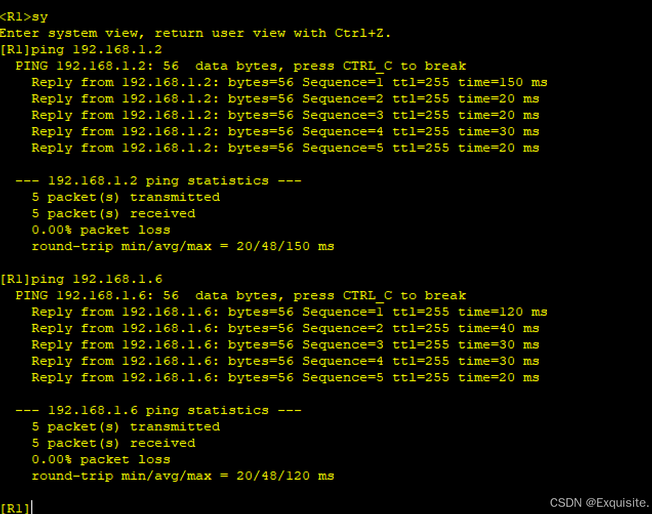
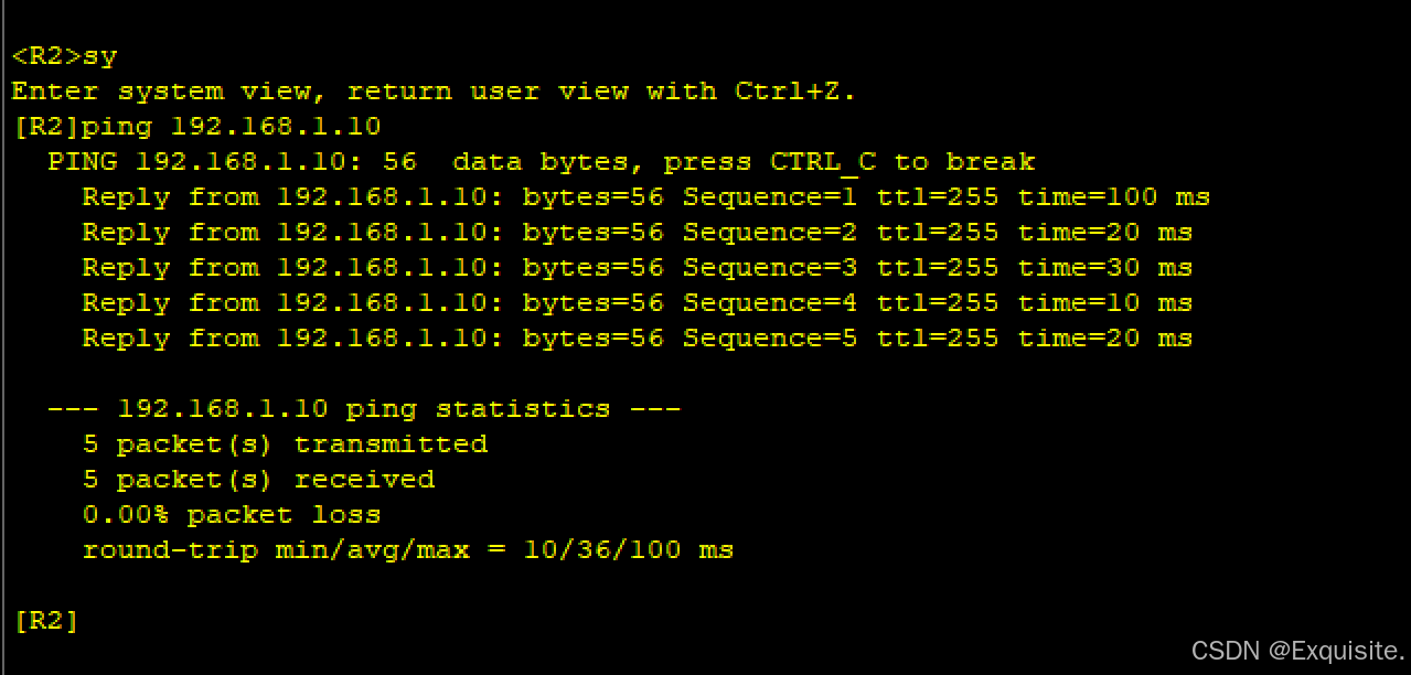
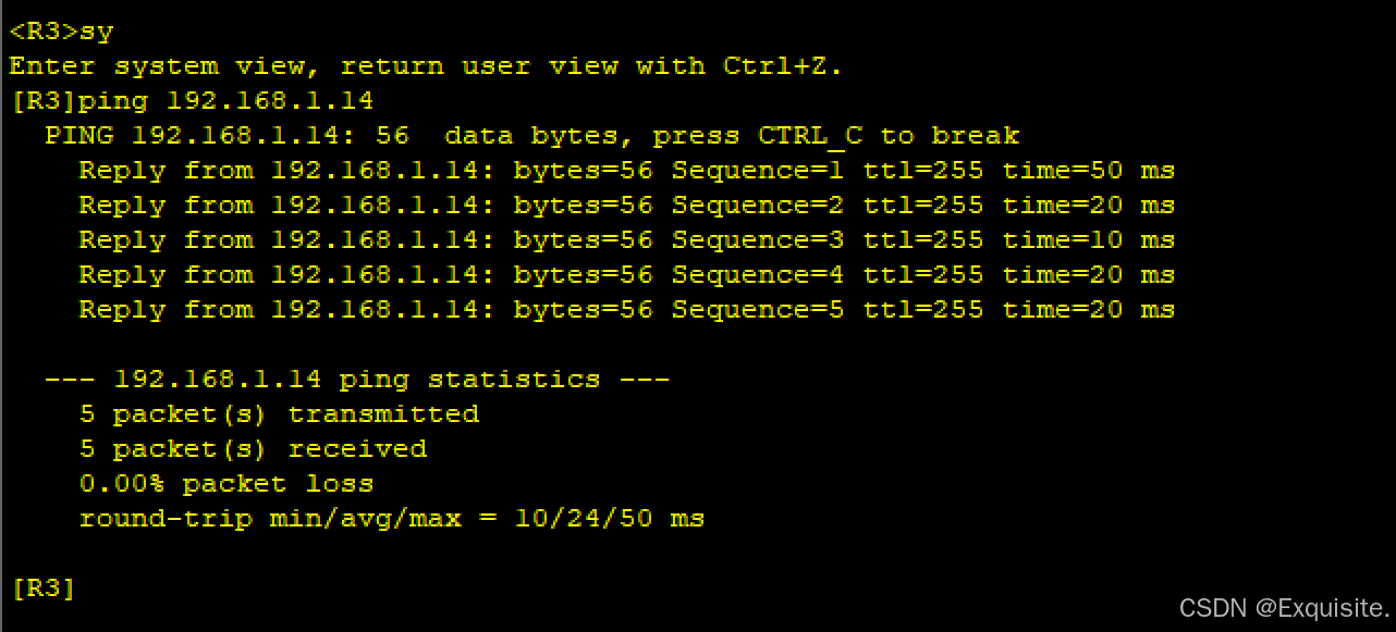
检查ping!!!
AR1----->AR2 // AR1------>AR3
AR2------->AR4
AR3------->AR4
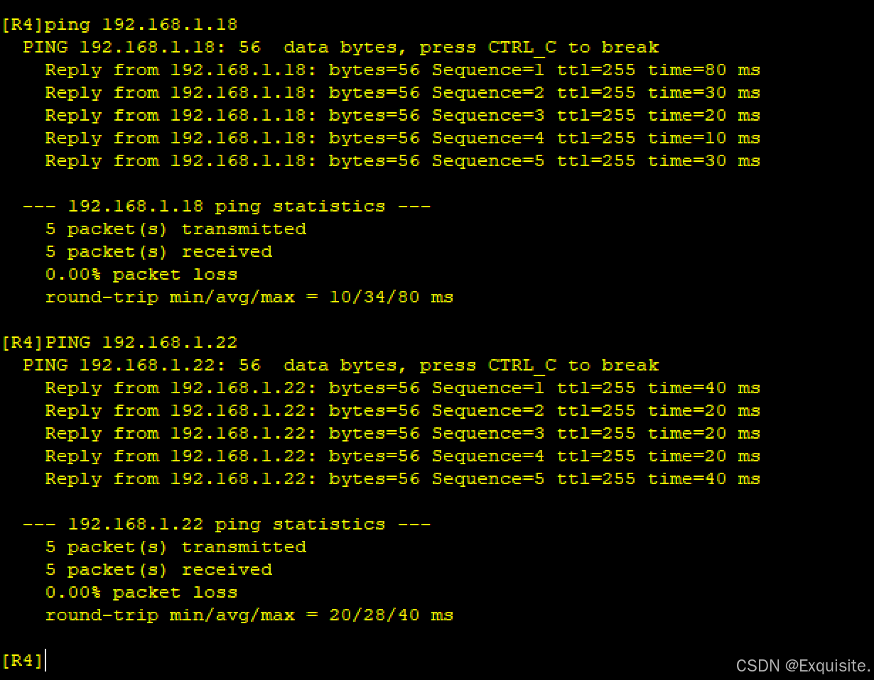
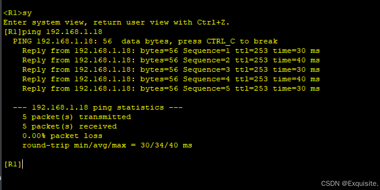
AR4------>AR5
3.配DHCP
[R5]dhcp enable
Info: The operation may take a few seconds. Please wait for a moment.done.
[R5]ip pool aa
Info: It's successful to create an IP address pool.
[R5-ip-pool-aa]network 192.168.1.160 mask 27
[R5-ip-pool-aa]gateway-list 192.168.1.161
[R5-ip-pool-aa]dns-list 8.8.8.8
[R5-ip-pool-aa]q
[R5]int g 0/0/2
[R5-GigabitEthernet0/0/2]dhcp select global
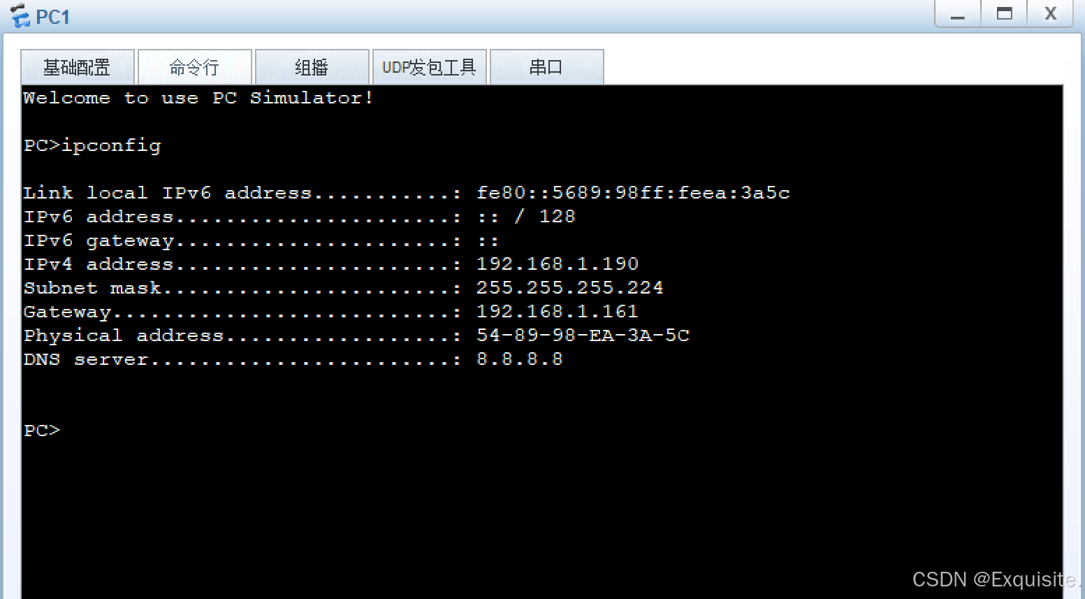
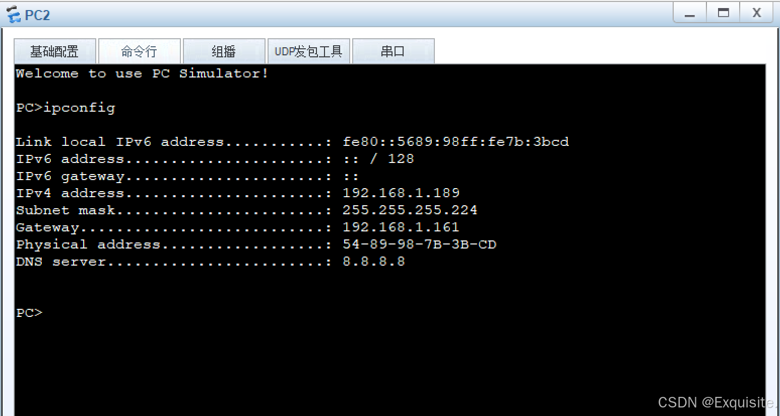
[R5-GigabitEthernet0/0/2]!!!检查PC!!!
PC1
PC2
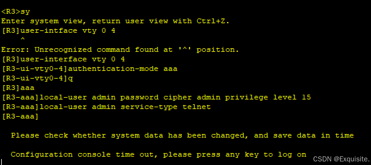
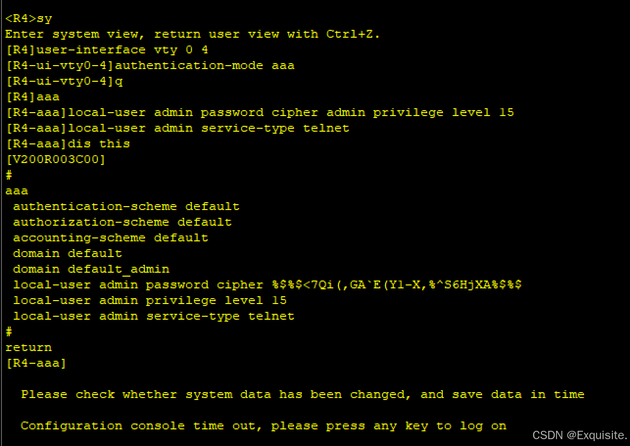
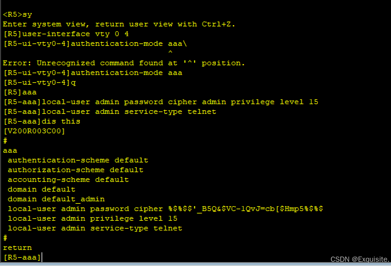
4.配Telnet
AR2
AR3
AR4
AR5
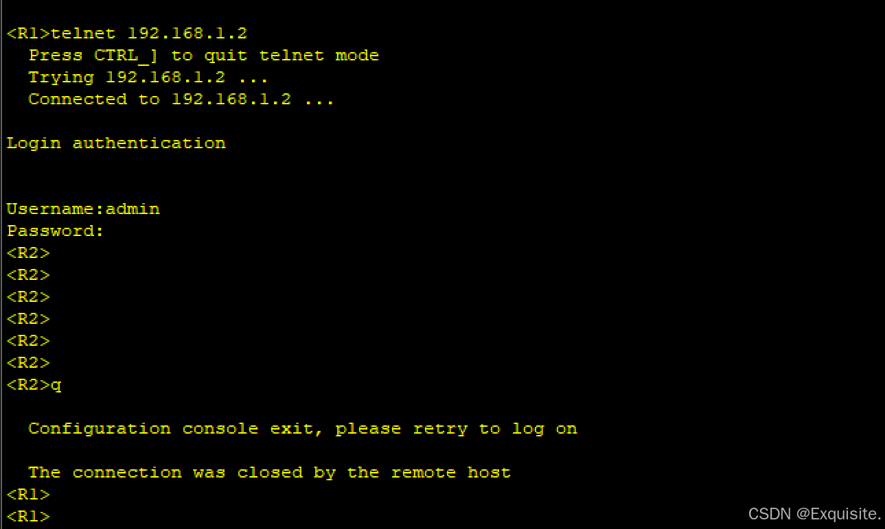
检查telnet!!!例如:AR1 ----> AR2 (其他相似)
5.配路由:未知网段/汇总网段
AR1
AR2
AR3
AR4
?检查是否可连通ping
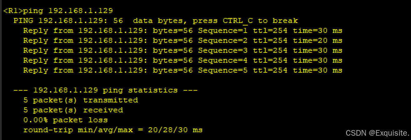
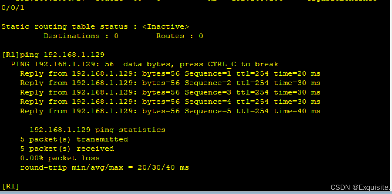
AR1------->192.168.1.129
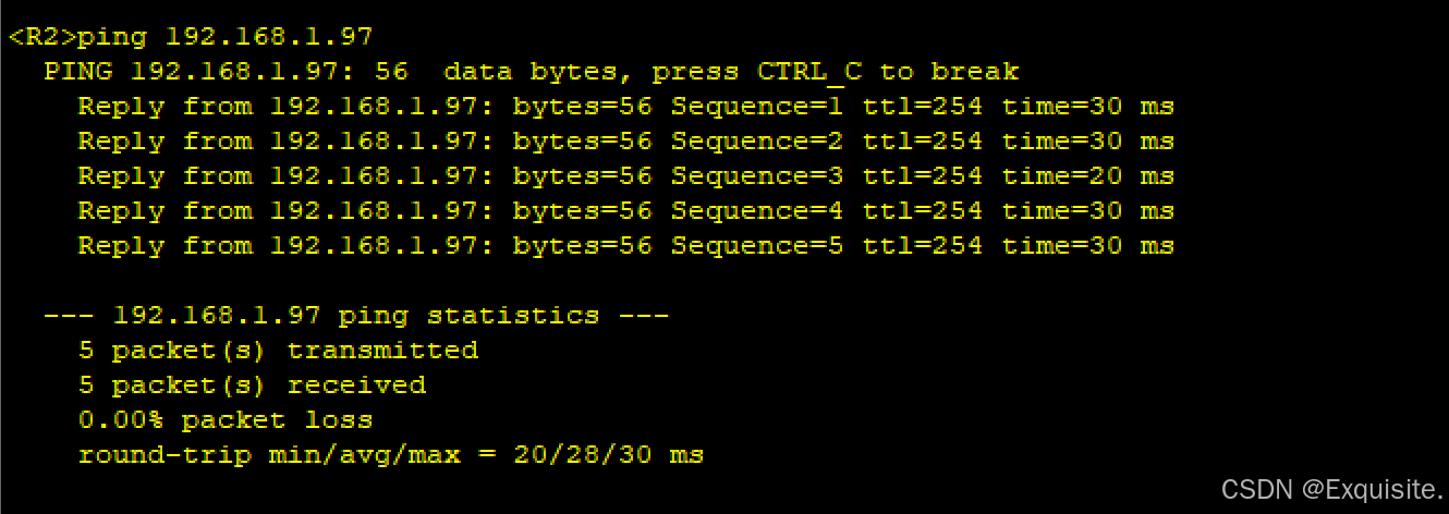
AR2------->AR3
6.缺省路由----不限定目的的路由 掩码0.0.0.0 0
AR1

AR2

AR3

AR4

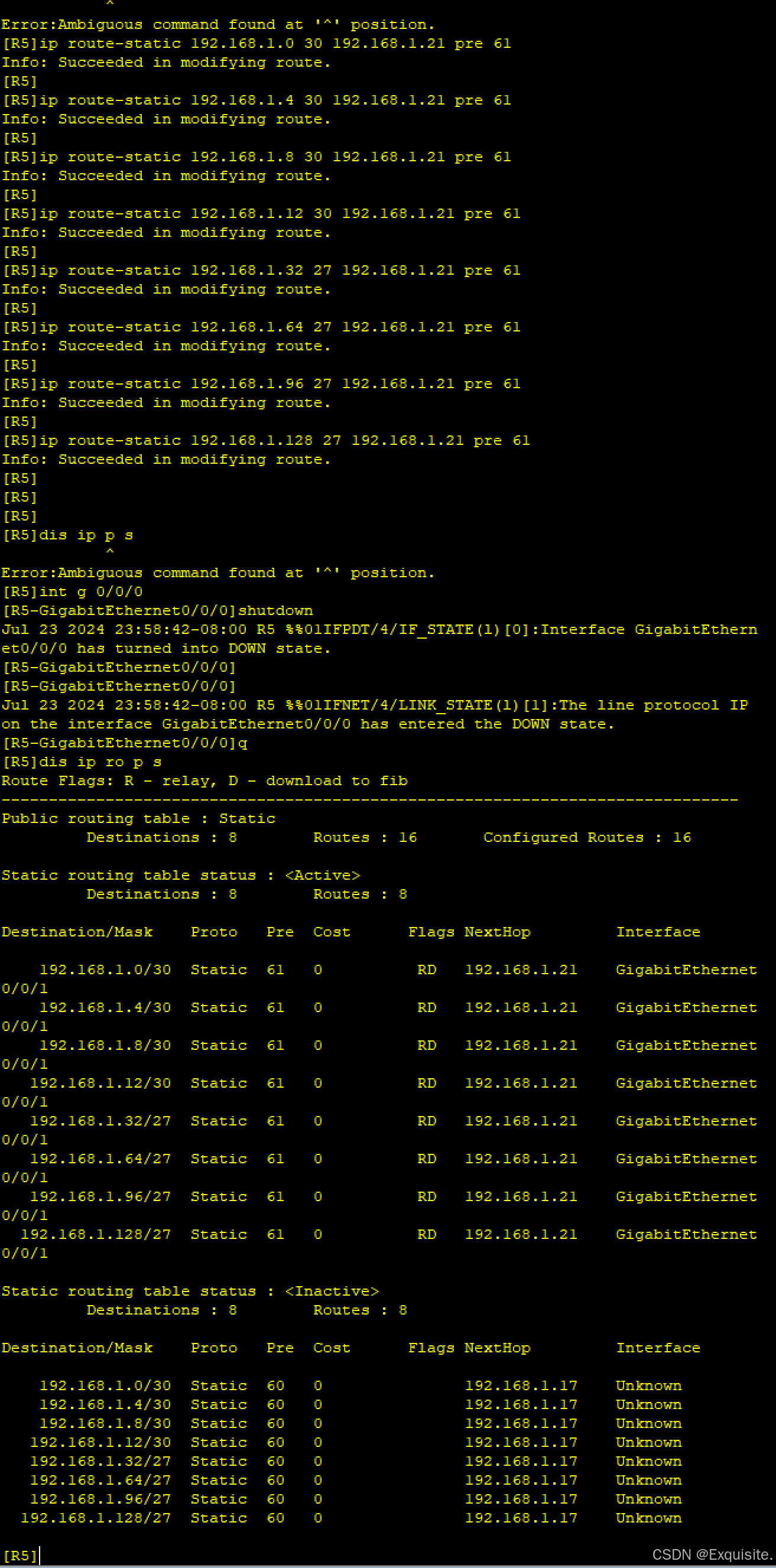
R1可传至1.18,但是不能回包,则没通
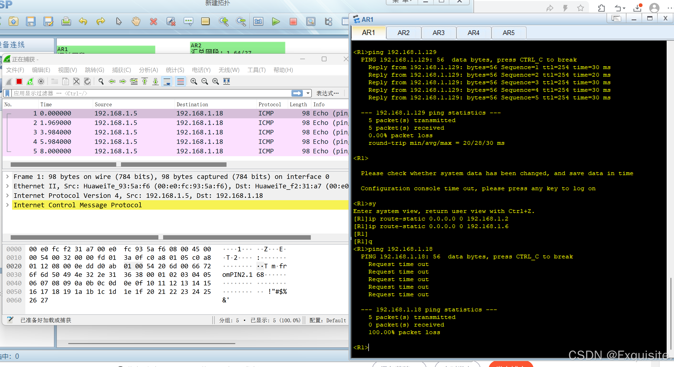
因为数据的连通是双向的如何实现呢?
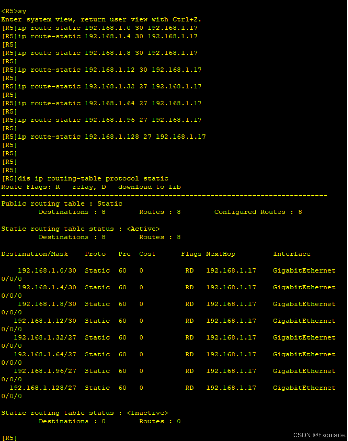
先要把R5路由补全,在检查,再看是否能ping通。
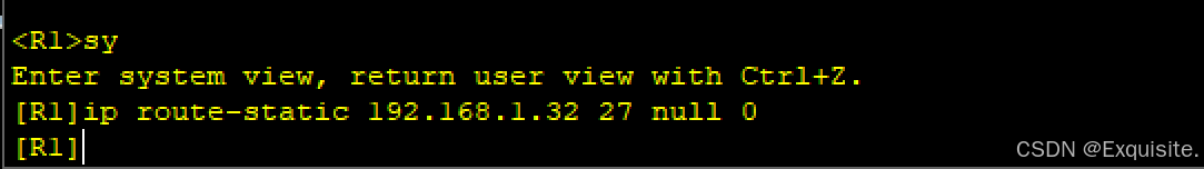
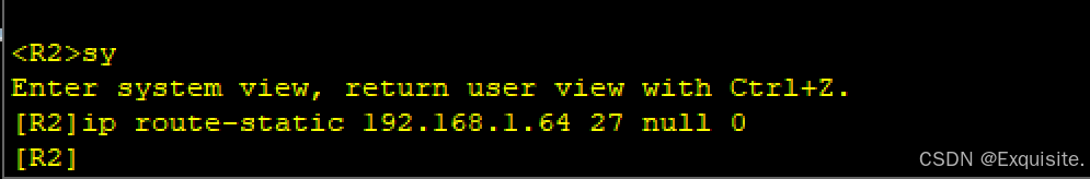
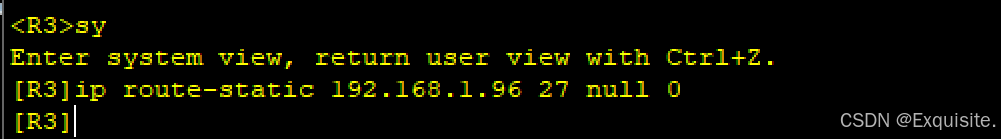
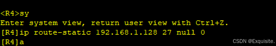
7.空接口路由-----环路产生的原因:因为缺省路由与黑洞路由器相遇;则会存在产生环路的隐患。流量消失在哪一个节点,谁就是黑洞路由器。
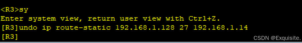
AR4的环回重复可删,AR1---AR3
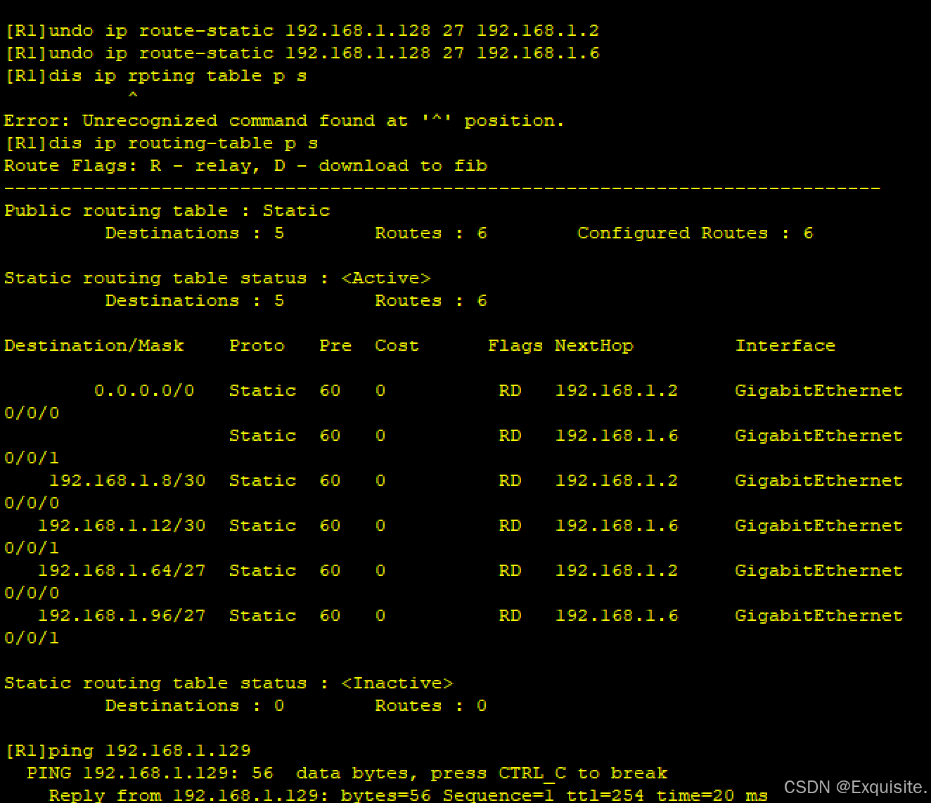

测试是否还能ping通
----可以,这是是因为缺省路由的作用
将AR1-AR4的环回设置空接口路由
8.浮动静态路由 -------- 只与R4和R5有关
AR4
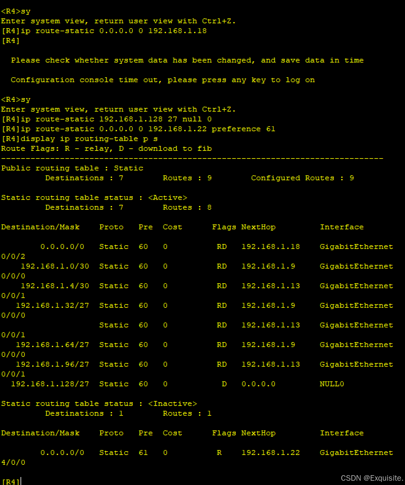
AR5
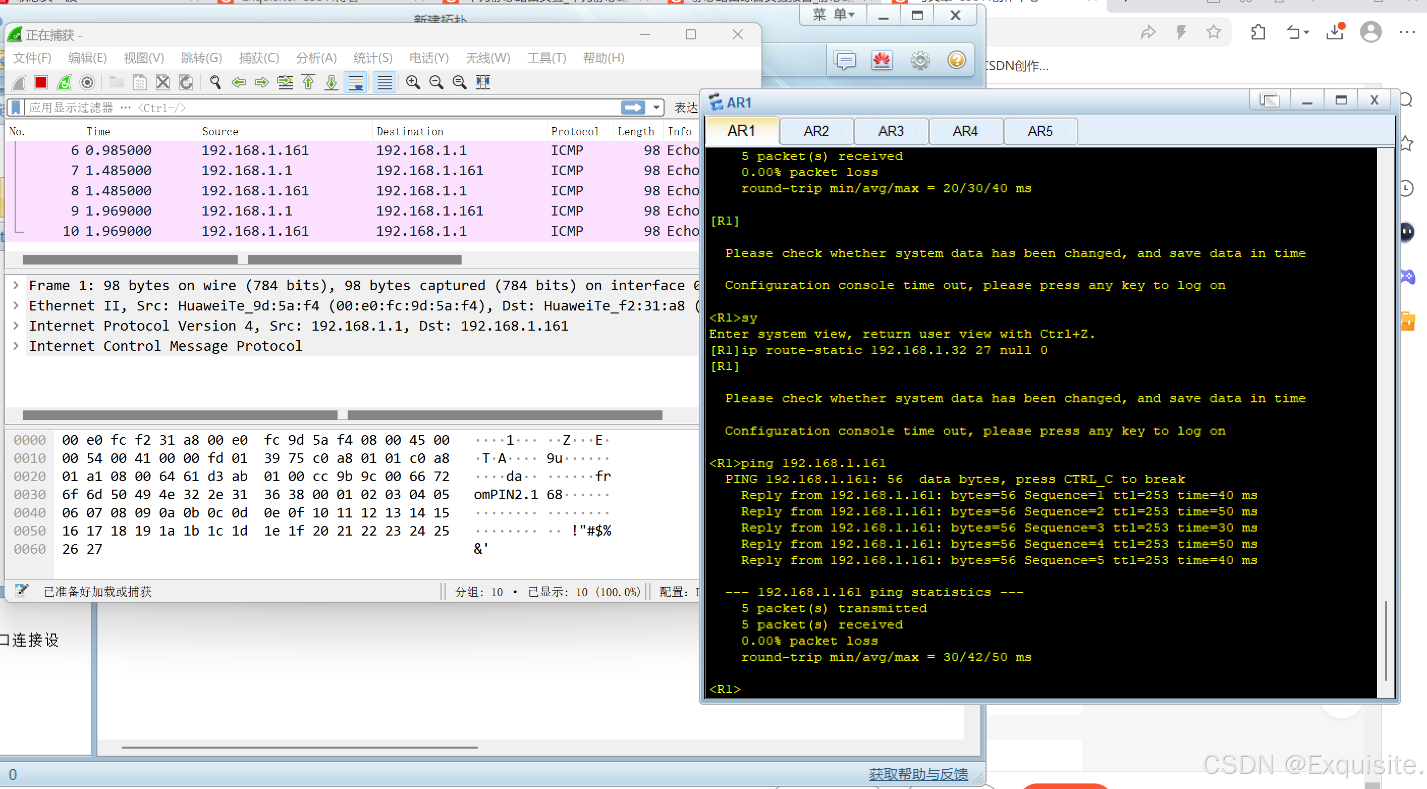
此时R1---->R5仍可通 -----全网可达


 377
377

 被折叠的 条评论
为什么被折叠?
被折叠的 条评论
为什么被折叠?
 到【灌水乐园】发言


