


在工程文件下新建文件夹,重命名Hardware(硬件),存放硬件驱动。回到kail5,新建文件夹Hardware,在魔术棒中添加路径。在Hardare文件夹下添加.c,.h文件,注意修改地址。
- 对于.c
#include "stm32f10x.h" // Device header

void LED\_Init(void){
    RCC\_APB2PeriphClockCmd(RCC_APB2Periph_GPIOA, ENABLE);  // Enable the clock for GPIOA peripheral
    GPIO_InitTypeDef GPIO_InitStructure;                   // Create a structure to configure GPIO pins
    GPIO_InitStructure.GPIO_Mode = GPIO_Mode_Out_PP;       // Configure GPIO pins as output in push-pull mode
    GPIO_InitStructure.GPIO_Pin = GPIO_Pin_1 | GPIO_Pin_2; // Specify the pins to be configured (Pin 1 and Pin 2)
    GPIO_InitStructure.GPIO_Speed = GPIO_Speed_50MHz;      // Set the maximum output speed to 50MHz
    GPIO\_Init(GPIOA, &GPIO_InitStructure);                 // Initialize GPIOA pins with the specified configuration
    GPIO\_SetBits(GPIOA, GPIO_Pin_1 | GPIO_Pin_2);          // Set the initial state of Pin 1 and Pin 2 to high (LEDs are initially off)
}

void LED1\_ON(void){
    GPIO\_ResetBits(GPIOA, GPIO_Pin_1);                     // Turn on LED1 by setting Pin 1 to low
}

void LED2\_ON(void){
    GPIO\_ResetBits(GPIOA, GPIO_Pin_2);                     // Turn on LED2 by setting Pin 2 to low
}

void LED1\_OFF(void){
    GPIO\_SetBits(GPIOA, GPIO_Pin_1);                     // Turn off LED1 by setting Pin 1 to high
}

void LED2\_OFF(void){
    GPIO\_SetBits(GPIOA, GPIO_Pin_2);                     // Turn off LED2 by setting Pin 2 to high
}
keil5可能对中文注释不兼容,所以我添加了英文注释。在.c文件中需要先添加头文件,再添加自己定义的函数。上代码实现了GPIOA 1,2引脚的初始化和高低电平的配置。
- 对于.h
#ifndef \_LED\_H
#define \_LED\_H

void LED\_Init(void);    // LED initialization function
void LED1\_ON(void);     // Turn on LED1
void LED2\_ON(void);     // Turn on LED2
void LED1\_OFF(void);    // Turn off LED1
void LED2\_OFF(void);    // Turn off LED2

#endif
前两行是声明,如果LED没有被定义,就定义LED。
ifndef 和 endif构成括号。
二、GPIO的读取
- GPIO_ReadInputDataBit()(读入指定引脚)

GPIO\_ReadInputDataBit(GPIOB,GPIO_Pin_1);
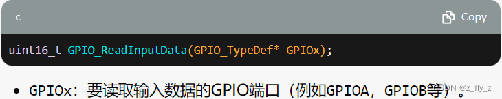
- GPIO_ReadInputData()(读入指定IO口)
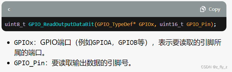
- GPIO_ReadOutputDataBit()(读入指定输出引脚状态)
- GPIO_ReadOutputData()(读入指定输出GPIO状态)
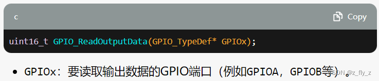
前两个读取输入,后两个读取输出的。
三、封装Key文件
了解1,2之后,可以将按键的开关模块化了。
- Key.c
#include "stm32f10x.h" // Device header
#include "Delay.h"

void Key\_Init(void) {
    RCC\_APB2PeriphClockCmd(RCC_APB2Periph_GPIOB, ENABLE);  // Enable clock for GPIOB
    GPIO_InitTypeDef GPIO_InitStructure;
    GPIO_InitStructure.GPIO_Mode = GPIO_Mode_IPU;  // Configure GPIO pins as input mode with pull-up resistors
    GPIO_InitStructure.GPIO_Pin = GPIO_Pin_1 | GPIO_Pin_11;  // Configure GPIO pins 1 and 11
    GPIO_InitStructure.GPIO_Speed = GPIO_Speed_50MHz;  // Set GPIO speed to 50MHz
    GPIO\_Init(GPIOB, &GPIO_InitStructure);  // Initialize GPIOB with the specified configuration
}

uint8\_t Key\_GetNum(void) {
    uint8\_t Key_Num = 0;

    if (GPIO\_ReadInputDataBit(GPIOB, GPIO_Pin_1) == 0) {  // Check if GPIO pin 1 is low
        Delay\_ms(20);  // Delay for debounce
        while (GPIO\_ReadInputDataBit(GPIOB, GPIO_Pin_1) == 0);  // Wait for GPIO pin 1 to become high again
        Delay\_ms(20);  // Delay for debounce
        Key_Num = 1;  // Set Key\_Num to 1
    }

    if (GPIO\_ReadInputDataBit(GPIOB, GPIO_Pin_11) == 0) {  // Check if GPIO pin 11 is low
        Delay\_ms(20);  // Delay for debounce
        while (GPIO\_ReadInputDataBit(GPIOB, GPIO_Pin_11) == 0);  // Wait for GPIO pin 11 to become high again
        Delay\_ms(20);  // Delay for debounce
        Key_Num = 2;  // Set Key\_Num to 2
    }

    return Key_Num;  // Return the value of Key\_Num
}
Delay_ms(20)软件按键消抖
最后
自我介绍一下,小编13年上海交大毕业,曾经在小公司待过,也去过华为、OPPO等大厂,18年进入阿里一直到现在。
深知大多数Java工程师,想要提升技能,往往是自己摸索成长,自己不成体系的自学效果低效漫长且无助。
因此收集整理了一份《2024年嵌入式&物联网开发全套学习资料》,初衷也很简单,就是希望能够帮助到想自学提升又不知道该从何学起的朋友,同时减轻大家的负担。

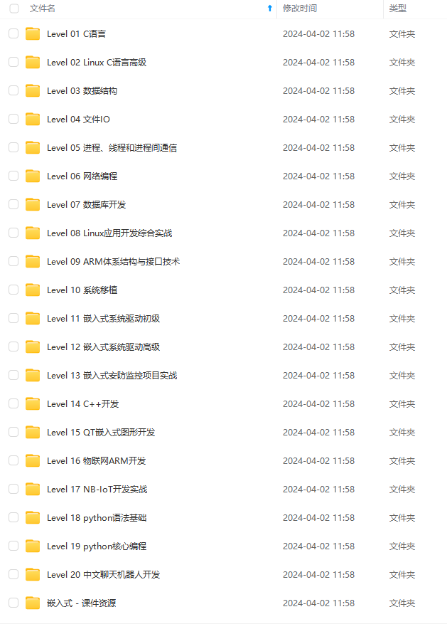

既有适合小白学习的零基础资料,也有适合3年以上经验的小伙伴深入学习提升的进阶课程,基本涵盖了95%以上嵌入式&物联网开发知识点,真正体系化!
如果你觉得这些内容对你有帮助,需要这份全套学习资料的朋友可以戳我获取!!
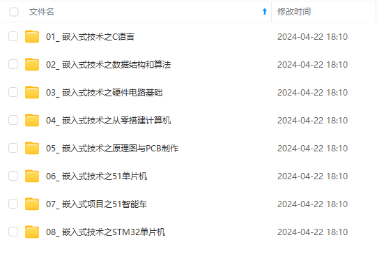
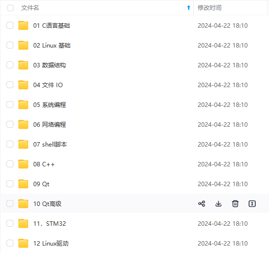
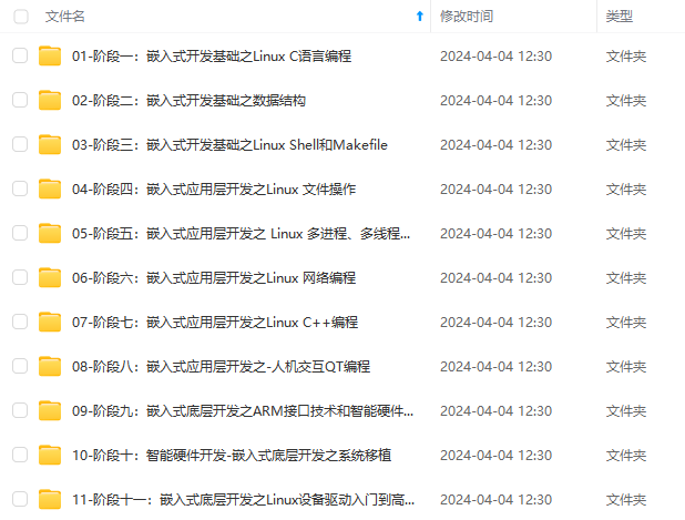
由于文件比较大,这里只是将部分目录大纲截图出来,每个节点里面都包含大厂面经、学习笔记、源码讲义、实战项目、讲解视频,并且后续会持续更新!!
%以上嵌入式&物联网开发知识点,真正体系化!**
如果你觉得这些内容对你有帮助,需要这份全套学习资料的朋友可以戳我获取!!
由于文件比较大,这里只是将部分目录大纲截图出来,每个节点里面都包含大厂面经、学习笔记、源码讲义、实战项目、讲解视频,并且后续会持续更新!!


 563
563

 被折叠的 条评论
为什么被折叠?
被折叠的 条评论
为什么被折叠?
 到【灌水乐园】发言


