


本文使用 esp32结合 TFT_eSPI库点亮了一块 ILI9341驱动的2.4寸串口屏,并运行了例程。
实验条件
乐鑫官网购买的esp32-pico-kit-d4
中景园购买的ILI9341驱动的2.4寸LCD串口屏幕
软件部分
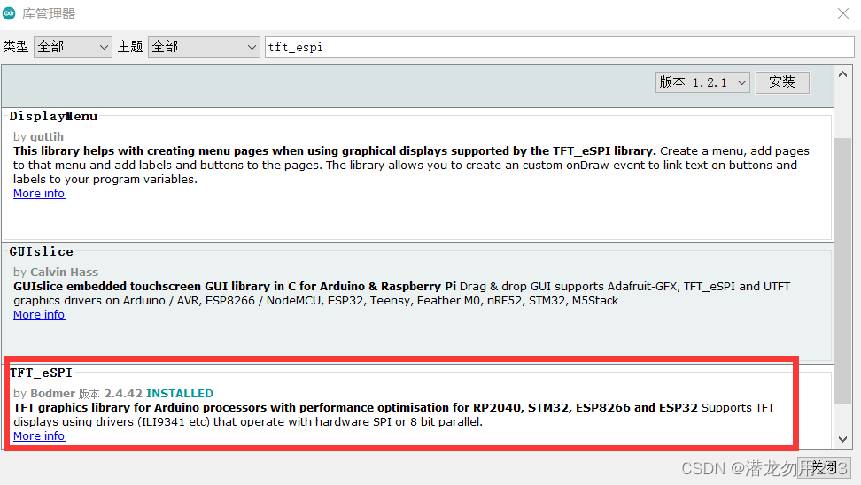
TFT_eSPI库的安装
TFT_eSPI库的介绍可参考链接:Arduino开发-TFT_eSPI库学习
打开arduino,工具->管理库->搜索 TFT_eSPI ,如下图所示,直接安装
安装位置见文件->首选项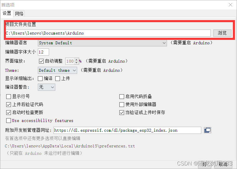
配置文件
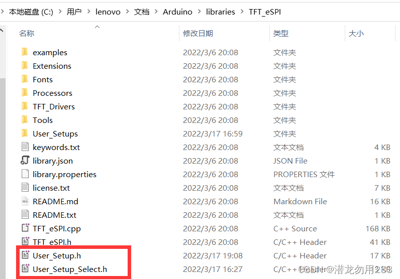
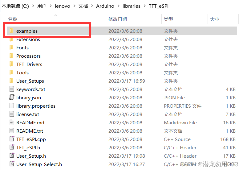
打开文件所在位置,重点关注 User_Setup.h 文件。
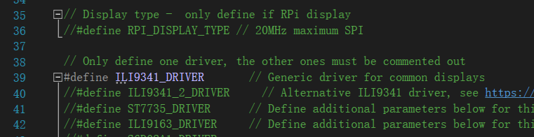
打开后,分4步配置:
1.选择正确的驱动型号:把ILI9341_DRIVER一行取消注释即可
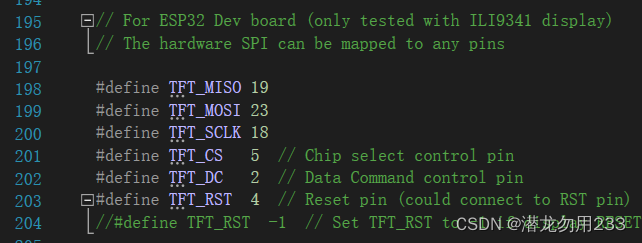
2.配置引脚:将ILI9341对应的引脚定义取消注释,并改为对应引脚(下文会再提及)
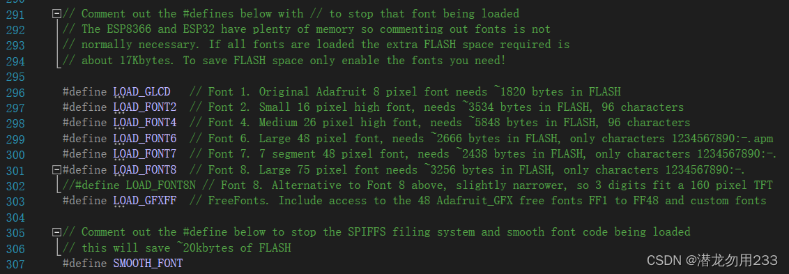
3.定义字库:未作修改
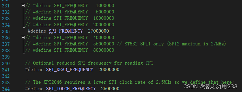
4.其他选项:主要是配置SPI频率,未作修改
详细代码如下:
//                            USER DEFINED SETTINGS
//   Set driver type, fonts to be loaded, pins used and SPI control method etc
//
//   See the User_Setup_Select.h file if you wish to be able to define multiple
//   setups and then easily select which setup file is used by the compiler.
//
//   If this file is edited correctly then all the library example sketches should
//   run without the need to make any more changes for a particular hardware setup!
//   Note that some sketches are designed for a particular TFT pixel width/height


// ##################################################################################
//
// Section 1. Call up the right driver file and any options for it
//
// ##################################################################################

// Define STM32 to invoke optimised processor support (only for STM32)
//#define STM32

// Defining the STM32 board allows the library to optimise the performance
// for UNO compatible "MCUfriend" style shields
//#define NUCLEO_64_TFT
//#define NUCLEO_144_TFT

// STM32 8 bit parallel only:
// If STN32 Port A or B pins 0-7 are used for 8 bit parallel data bus bits 0-7
// then this will improve rendering performance by a factor of ~8x
//#define STM_PORTA_DATA_BUS
//#define STM_PORTB_DATA_BUS

// Tell the library to use 8 bit parallel mode (otherwise SPI is assumed)
//#define TFT_PARALLEL_8_BIT

// Display type -  only define if RPi display
//#define RPI_DISPLAY_TYPE // 20MHz maximum SPI

// Only define one driver, the other ones must be commented out
#define ILI9341_DRIVER       // Generic driver for common displays
//#define ILI9341_2_DRIVER     // Alternative ILI9341 driver, see https://github.com/Bodmer/TFT_eSPI/issues/1172
//#define ST7735_DRIVER      // Define additional parameters below for this display
//#define ILI9163_DRIVER     // Define additional parameters below for this display
//#define S6D02A1_DRIVER
//#define RPI_ILI9486_DRIVER // 20MHz maximum SPI
//#define HX8357D_DRIVER
//#define ILI9481_DRIVER
//#define ILI9486_DRIVER
//#define ILI9488_DRIVER     // WARNING: Do not connect ILI9488 display SDO to MISO if other devices share the SPI bus (TFT SDO does NOT tristate when CS is high)
//#define ST7789_DRIVER      // Full configuration option, define additional parameters below for this display
//#define ST7789_2_DRIVER    // Minimal configuration option, define additional parameters below for this display
//#define R61581_DRIVER
//#define RM68140_DRIVER
//#define ST7796_DRIVER
//#define SSD1351_DRIVER
//#define SSD1963_480_DRIVER
//#define SSD1963_800_DRIVER
//#define SSD1963_800ALT_DRIVER
//#define ILI9225_DRIVER
//#define GC9A01_DRIVER

// Some displays support SPI reads via the MISO pin, other displays have a single
// bi-directional SDA pin and the library will try to read this via the MOSI line.
// To use the SDA line for reading data from the TFT uncomment the following line:

// #define TFT_SDA_READ      // This option is for ESP32 ONLY, tested with ST7789 and GC9A01 display only

// For ST7735, ST7789 and ILI9341 ONLY, define the colour order IF the blue and red are swapped on your display
// Try ONE option at a time to find the correct colour order for your display

//  #define TFT_RGB_ORDER TFT_RGB  // Colour order Red-Green-Blue
//  #define TFT_RGB_ORDER TFT_BGR  // Colour order Blue-Green-Red

// For M5Stack ESP32 module with integrated ILI9341 display ONLY, remove // in line below

// #define M5STACK

// For ST7789, ST7735, ILI9163 and GC9A01 ONLY, define the pixel width and height in portrait orientation
// #define TFT_WIDTH  80
// #define TFT_WIDTH  128
// #define TFT_WIDTH  240 // ST7789 240 x 240 and 240 x 320
// #define TFT_HEIGHT 160
// #define TFT_HEIGHT 128
// #define TFT_HEIGHT 240 // ST7789 240 x 240
// #define TFT_HEIGHT 320 // ST7789 240 x 320
// #define TFT_HEIGHT 240 // GC9A01 240 x 240

// For ST7735 ONLY, define the type of display, originally this was based on the
// colour of the tab on the screen protector film but this is not always true, so try
// out the different options below if the screen does not display graphics correctly,
// e.g. colours wrong, mirror images, or stray pixels at the edges.
// Comment out ALL BUT ONE of these options for a ST7735 display driver, save this
// this User_Setup file, then rebuild and upload the sketch to the board again:

// #define ST7735_INITB
// #define ST7735_GREENTAB
// #define ST7735_GREENTAB2
// #define ST7735_GREENTAB3
// #define ST7735_GREENTAB128    // For 128 x 128 display
// #define ST7735_GREENTAB160x80 // For 160 x 80 display (BGR, inverted, 26 offset)
// #define ST7735_REDTAB
// #define ST7735_BLACKTAB
// #define ST7735_REDTAB160x80   // For 160 x 80 display with 24 pixel offset

// If colours are inverted (white shows as black) then uncomment one of the next
// 2 lines try both options, one of the options should correct the inversion.

// #define TFT_INVERSION_ON
// #define TFT_INVERSION_OFF


// ##################################################################################
//
// Section 2. Define the pins that are used to interface with the display here
//
// ##################################################################################

// If a backlight control signal is available then define the TFT_BL pin in Section 2
// below. The backlight will be turned ON when tft.begin() is called, but the library
// needs to know if the LEDs are ON with the pin HIGH or LOW. If the LEDs are to be
// driven with a PWM signal or turned OFF/ON then this must be handled by the user
// sketch. e.g. with digitalWrite(TFT_BL, LOW);

// #define TFT_BL   32            // LED back-light control pin
// #define TFT_BACKLIGHT_ON HIGH  // Level to turn ON back-light (HIGH or LOW)


// We must use hardware SPI, a minimum of 3 GPIO pins is needed.
// Typical setup for ESP8266 NodeMCU ESP-12 is :
//
// Display SDO/MISO  to NodeMCU pin D6 (or leave disconnected if not reading TFT)
// Display LED       to NodeMCU pin VIN (or 5V, see below)
// Display SCK       to NodeMCU pin D5
// Display SDI/MOSI  to NodeMCU pin D7
// Display DC (RS/AO)to NodeMCU pin D3
// Display RESET     to NodeMCU pin D4 (or RST, see below)
// Display CS        to NodeMCU pin D8 (or GND, see below)
// Display GND       to NodeMCU pin GND (0V)
// Display VCC       to NodeMCU 5V or 3.3V
//
// The TFT RESET pin can be connected to the NodeMCU RST pin or 3.3V to free up a control pin
//
// The DC (Data Command) pin may be labelled AO or RS (Register Select)
//
// With some displays such as the ILI9341 the TFT CS pin can be connected to GND if no more
// SPI devices (e.g. an SD Card) are connected, in this case comment out the #define TFT_CS
// line below so it is NOT defined. Other displays such at the ST7735 require the TFT CS pin
// to be toggled during setup, so in these cases the TFT_CS line must be defined and connected.
//
// The NodeMCU D0 pin can be used for RST
//
//
// Note: only some versions of the NodeMCU provide the USB 5V on the VIN pin
// If 5V is not available at a pin you can use 3.3V but backlight brightness
// will be lower.


// ###### EDIT THE PIN NUMBERS IN THE LINES FOLLOWING TO SUIT YOUR ESP8266 SETUP ######

// For NodeMCU - use pin numbers in the form PIN_Dx where Dx is the NodeMCU pin designation
//#define TFT_CS   PIN_D8  // Chip select control pin D8
//#define TFT_DC   PIN_D3  // Data Command control pin
//#define TFT_RST  PIN_D4  // Reset pin (could connect to NodeMCU RST, see next line)
//#define TFT_RST  -1    // Set TFT_RST to -1 if the display RESET is connected to NodeMCU RST or 3.3V

//#define TFT_BL PIN_D1  // LED back-light (only for ST7789 with backlight control pin)

//#define TOUCH_CS PIN_D2     // Chip select pin (T_CS) of touch screen

//#define TFT_WR PIN_D2       // Write strobe for modified Raspberry Pi TFT only


// ######  FOR ESP8266 OVERLAP MODE EDIT THE PIN NUMBERS IN THE FOLLOWING LINES  ######

// Overlap mode shares the ESP8266 FLASH SPI bus with the TFT so has a performance impact
// but saves pins for other functions. It is best not to connect MISO as some displays
// do not tristate that line when chip select is high!
// Note: Only one SPI device can share the FLASH SPI lines, so a SPI touch controller
// cannot be connected as well to the same SPI signals.
// On NodeMCU 1.0 SD0=MISO, SD1=MOSI, CLK=SCLK to connect to TFT in overlap mode
// On NodeMCU V3  S0 =MISO, S1 =MOSI, S2 =SCLK
// In ESP8266 overlap mode the following must be defined

//#define TFT_SPI_OVERLAP

// In ESP8266 overlap mode the TFT chip select MUST connect to pin D3
//#define TFT_CS   PIN_D3
//#define TFT_DC   PIN_D5  // Data Command control pin
//#define TFT_RST  PIN_D4  // Reset pin (could connect to NodeMCU RST, see next line)
//#define TFT_RST  -1  // Set TFT_RST to -1 if the display RESET is connected to NodeMCU RST or 3.3V


// ###### EDIT THE PIN NUMBERS IN THE LINES FOLLOWING TO SUIT YOUR ESP32 SETUP   ######

// For ESP32 Dev board (only tested with ILI9341 display)
// The hardware SPI can be mapped to any pins

#define TFT_MISO 19
#define TFT_MOSI 23
#define TFT_SCLK 18
#define TFT_CS   5  // Chip select control pin
#define TFT_DC   2  // Data Command control pin
#define TFT_RST  4  // Reset pin (could connect to RST pin)
//#define TFT_RST  -1  // Set TFT_RST to -1 if display RESET is connected to ESP32 board RST

// For ESP32 Dev board (only tested with GC9A01 display)
// The hardware SPI can be mapped to any pins

//#define TFT_MOSI 15 // In some display driver board, it might be written as "SDA" and so on.
//#define TFT_SCLK 14
//#define TFT_CS   5  // Chip select control pin
//#define TFT_DC   27  // Data Command control pin
//#define TFT_RST  33  // Reset pin (could connect to Arduino RESET pin)
//#define TFT_BL   22  // LED back-light

//#define TOUCH_CS 33     // Chip select pin (T_CS) of touch screen

//#define TFT_WR 22    // Write strobe for modified Raspberry Pi TFT only

// For the M5Stack module use these #define lines
//#define TFT_MISO 19
//#define TFT_MOSI 23
//#define TFT_SCLK 18
//#define TFT_CS   14  // Chip select control pin
//#define TFT_DC   27  // Data Command control pin
//#define TFT_RST  33  // Reset pin (could connect to Arduino RESET pin)
//#define TFT_BL   32  // LED back-light (required for M5Stack)

// ######       EDIT THE PINs BELOW TO SUIT YOUR ESP32 PARALLEL TFT SETUP        ######

// The library supports 8 bit parallel TFTs with the ESP32, the pin
// selection below is compatible with ESP32 boards in UNO format.
// Wemos D32 boards need to be modified, see diagram in Tools folder.
// Only ILI9481 and ILI9341 based displays have been tested!

// Parallel bus is only supported for the STM32 and ESP32
// Example below is for ESP32 Parallel interface with UNO displays

// Tell the library to use 8 bit parallel mode (otherwise SPI is assumed)
//#define TFT_PARALLEL_8_BIT

// The ESP32 and TFT the pins used for testing are:
//#define TFT_CS   33  // Chip select control pin (library pulls permanently low
//#define TFT_DC   15  // Data Command control pin - must use a pin in the range 0-31
//#define TFT_RST  32  // Reset pin, toggles on startup

//#define TFT_WR    4  // Write strobe control pin - must use a pin in the range 0-31
//#define TFT_RD    2  // Read strobe control pin

//#define TFT_D0   12  // Must use pins in the range 0-31 for the data bus
//#define TFT_D1   13  // so a single register write sets/clears all bits.
//#define TFT_D2   26  // Pins can be randomly assigned, this does not affect
//#define TFT_D3   25  // TFT screen update performance.
//#define TFT_D4   17
//#define TFT_D5   16
//#define TFT_D6   27
//#define TFT_D7   14

// ######       EDIT THE PINs BELOW TO SUIT YOUR STM32 SPI TFT SETUP        ######

// The TFT can be connected to SPI port 1 or 2
//#define TFT_SPI_PORT 1 // SPI port 1 maximum clock rate is 55MHz
//#define TFT_MOSI PA7
//#define TFT_MISO PA6
//#define TFT_SCLK PA5

//#define TFT_SPI_PORT 2 // SPI port 2 maximum clock rate is 27MHz
//#define TFT_MOSI PB15
//#define TFT_MISO PB14
//#define TFT_SCLK PB13

// Can use Ardiuno pin references, arbitrary allocation, TFT_eSPI controls chip select
//#define TFT_CS   D5 // Chip select control pin to TFT CS
//#define TFT_DC   D6 // Data Command control pin to TFT DC (may be labelled RS = Register Select)
//#define TFT_RST  D7 // Reset pin to TFT RST (or RESET)
// OR alternatively, we can use STM32 port reference names PXnn
//#define TFT_CS   PE11 // Nucleo-F767ZI equivalent of D5
//#define TFT_DC   PE9  // Nucleo-F767ZI equivalent of D6
//#define TFT_RST  PF13 // Nucleo-F767ZI equivalent of D7

//#define TFT_RST  -1   // Set TFT_RST to -1 if the display RESET is connected to processor reset
                        // Use an Arduino pin for initial testing as connecting to processor reset
                        // may not work (pulse too short at power up?)

// ##################################################################################
//
// Section 3. Define the fonts that are to be used here
//
// ##################################################################################

// Comment out the #defines below with // to stop that font being loaded
// The ESP8366 and ESP32 have plenty of memory so commenting out fonts is not
// normally necessary. If all fonts are loaded the extra FLASH space required is
// about 17Kbytes. To save FLASH space only enable the fonts you need!

#define LOAD_GLCD   // Font 1. Original Adafruit 8 pixel font needs ~1820 bytes in FLASH
#define LOAD_FONT2  // Font 2. Small 16 pixel high font, needs ~3534 bytes in FLASH, 96 characters
#define LOAD_FONT4  // Font 4. Medium 26 pixel high font, needs ~5848 bytes in FLASH, 96 characters
#define LOAD_FONT6  // Font 6. Large 48 pixel font, needs ~2666 bytes in FLASH, only characters 1234567890:-.apm
#define LOAD_FONT7  // Font 7. 7 segment 48 pixel font, needs ~2438 bytes in FLASH, only characters 1234567890:-.
#define LOAD_FONT8  // Font 8. Large 75 pixel font needs ~3256 bytes in FLASH, only characters 1234567890:-.
//#define LOAD_FONT8N // Font 8. Alternative to Font 8 above, slightly narrower, so 3 digits fit a 160 pixel TFT
#define LOAD_GFXFF  // FreeFonts. Include access to the 48 Adafruit_GFX free fonts FF1 to FF48 and custom fonts

// Comment out the #define below to stop the SPIFFS filing system and smooth font code being loaded
// this will save ~20kbytes of FLASH
#define SMOOTH_FONT


// ##################################################################################
//
// Section 4. Other options
//
// ##################################################################################

// For RP2040 processor and SPI displays, uncomment the following line to use the PIO interface.
//#define RP2040_PIO_SPI // Leave commented out to use standard RP2040 SPI port interface

// For the RP2040 processor define the SPI port channel used (default 0 if undefined)
//#define TFT_SPI_PORT 1 // Set to 0 if SPI0 pins are used, or 1 if spi1 pins used

// For the STM32 processor define the SPI port channel used (default 1 if undefined)
//#define TFT_SPI_PORT 2 // Set to 1 for SPI port 1, or 2 for SPI port 2

// Define the SPI clock frequency, this affects the graphics rendering speed. Too
// fast and the TFT driver will not keep up and display corruption appears.
// With an ILI9341 display 40MHz works OK, 80MHz sometimes fails
// With a ST7735 display more than 27MHz may not work (spurious pixels and lines)
// With an ILI9163 display 27 MHz works OK.

// #define SPI_FREQUENCY   1000000
// #define SPI_FREQUENCY   5000000
// #define SPI_FREQUENCY  10000000
// #define SPI_FREQUENCY  20000000
 #define SPI_FREQUENCY  27000000
// #define SPI_FREQUENCY  40000000
// #define SPI_FREQUENCY  55000000 // STM32 SPI1 only (SPI2 maximum is 27MHz)
// #define SPI_FREQUENCY  80000000

// Optional reduced SPI frequency for reading TFT
#define SPI_READ_FREQUENCY  20000000

// The XPT2046 requires a lower SPI clock rate of 2.5MHz so we define that here:
#define SPI_TOUCH_FREQUENCY  2500000

// The ESP32 has 2 free SPI ports i.e. VSPI and HSPI, the VSPI is the default.
// If the VSPI port is in use and pins are not accessible (e.g. TTGO T-Beam)
// then uncomment the following line:
//#define USE_HSPI_PORT

// Comment out the following #define if "SPI Transactions" do not need to be
// supported. When commented out the code size will be smaller and sketches will
// run slightly faster, so leave it commented out unless you need it!

// Transaction support is needed to work with SD library but not needed with TFT_SdFat
// Transaction support is required if other SPI devices are connected.

// Transactions are automatically enabled by the library for an ESP32 (to use HAL mutex)
// so changing it here has no effect

// #define SUPPORT_TRANSACTIONS
硬件部分
esp32
打开数据手册,找到引脚定义,选用VSPI,如下所示
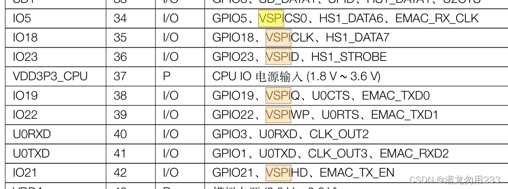
总结引脚如下:
| SPI四线全双工信号总线 | VSPI信号总线 | ESP32引脚编号 |
|---|---|---|
| MOSI | VSPID | 23 |
| MISO | VSPIQ | 19 |
| CS | VSPICS0 | 5 |
| CLK | VSPICLK | 18 |
关于SPI、HSPI、VSPI的区别,可参考:ESP32之软件SPI驱动及SPI、HSPI和VSPI的理解
LCD串口屏
打开中景园数据手册《中景园ZJY240S110TTG01技术资料》,找到引脚定义:
| 引脚 | 说明 |
|---|---|
| GND | 接地 |
| VCC | 接3.3V |
| CLK | 时钟信号,接SPICLK |
| MOSI | SPI信号读入 |
| RES | Reset复位信号,低-初始化,高-正常工作 |
| DC | Data/Command控制信号,低-command,高-data |
| BLK | 背光控制开关,低-关闭背光,高-打开背光(默认) |
| MISO | 触摸信号输出 |
| CS1 | LCD显示片选,低有效 |
| CS2 | 触摸片选,低有效 |
| PEN | 触摸中断 |
接线方式
| LCD引脚 | ESP32引脚 |
|---|---|
| GND | GND |
| VCC | 3V3 |
| CLK | 18(SPI-CLK) |
| MOSI | 23(SPI-MOSI) |
| RES | 4 |
| DC | 2 |
| BLK | 悬空 |
| MISO | 19(SPI-MISO) |
| CS1 | 5(SPI-CS) |
| CS2 | 悬空 |
| PEN | 悬空 |
注意,配置文件中引脚定义要与上表保持一致
实验部分
打开TFT_eSPI库的examples,随便选择一个例程验证即可。
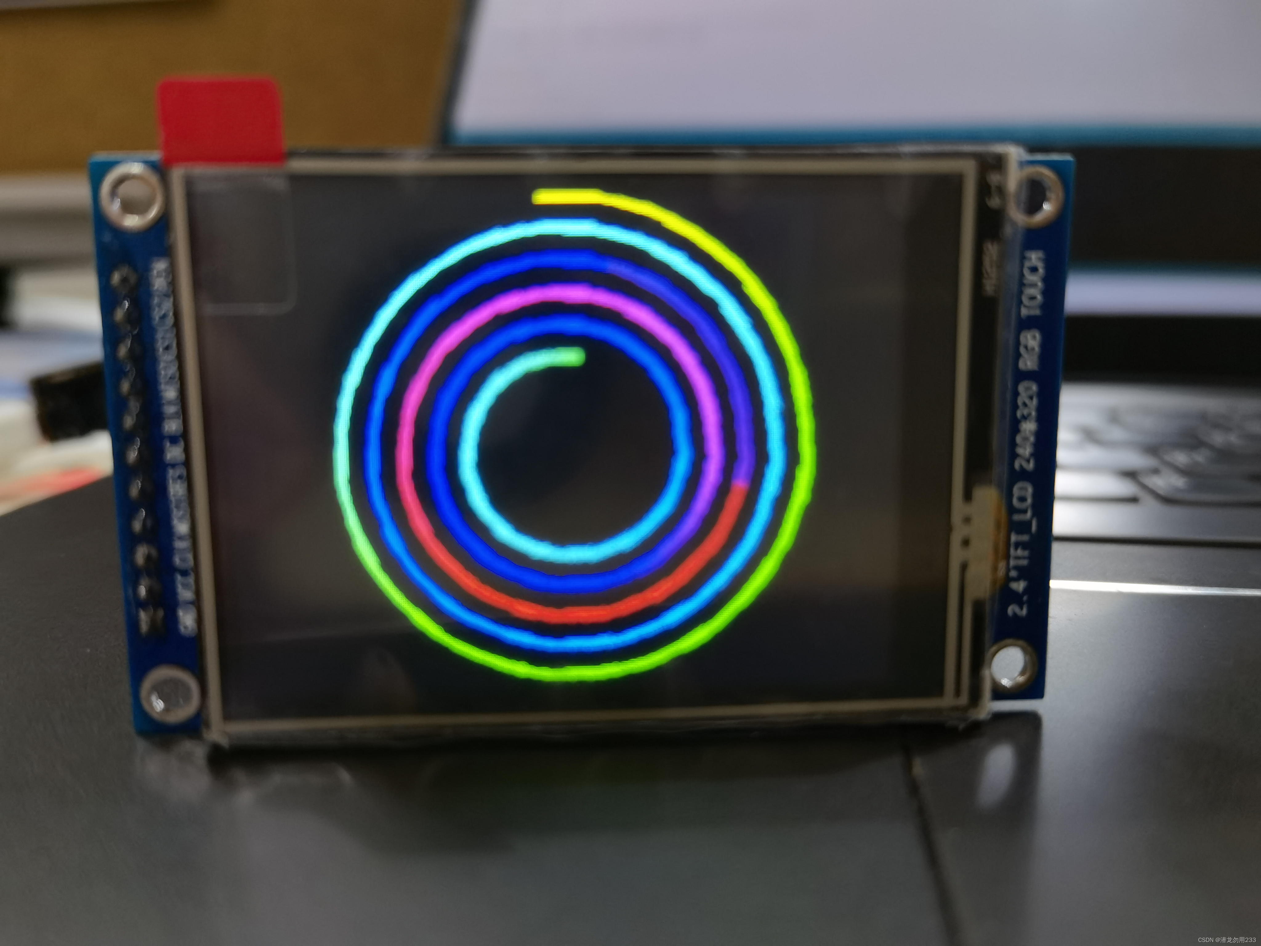
我的屏幕尺寸为320*240,故选用.\320 x 240\TFT_FillArcSpiral示例进行验证,运行结果如下:
参考文章
ST7789:
玩转 ESP32 + Arduino(二十八) TFT_eSPI库驱动ST7789
玩转 ESP32 + Arduino(二十九) TFT_eSPI库驱动ST7789之动画专题
很详细地介绍了TFT_eSPI库API的一篇文章:ESP32_驱动TFT彩屏_Arduino
关于使用User_Setup_Select.h文件配置的方法:ESP32-TFT_eSPI库中的使用前设置
关于配置文件的详细讲解:ESP32_Arduino_TFT_eSPI的使用记录


 519
519

 被折叠的 条评论
为什么被折叠?
被折叠的 条评论
为什么被折叠?
 到【灌水乐园】发言


