


Shader
Android 中绘图时渐变着色需要使用android.graphics.Shader类,该类有几个子类:如下图所示

- BitmapShader 图片渲染
- LinearGradient 线性梯度渲染
- RadialGradient 径向渲染/环形梯度渲染
- SweepGradient 扫描梯度渲染
- ComposeShader 混合渲染
BitmapShader
Public constructors
BitmapShader
    BitmapShader (Bitmap bitmap,
        Shader.TileMode tileX,
        Shader.TileMode tileY)
Call this to create a new shader that will draw with a bitmap.
意思是调用该构造方法可以创建一个用bitmap绘制的新着色器。该构造方法有三个参数,第一个是bitmap对象,第二、三个分别表示X、Y轴的渲染模式。如图1所示为

图1 bitmapShader图片渲染模式效果图(CLAMP平铺模式)
实现上图效果的主要代码如下:
int w = getWidth();
int h = getHeight();
Bitmap bmp = BitmapFactory.decodeResource(getResources(), R.mipmap.dog);
shader = new BitmapShader(bmp, Shader.TileMode.CLAMP, Shader.TileMode.REPEAT);
mpaint.setTextSize(100.0f);
mpaint.setColor(Color.RED);
mpaint.setTypeface(Typeface.DEFAULT_BOLD);
mpaint.setTextAlign(Paint.Align.LEFT);
mpaint.setShader(shader);
canvas.drawText("小猫猫,小狗狗", 30.0f, h / 2, mpaint);
图中的渲染模式使用了X轴(水平方向)使用了CLAMP(边缘拉伸)模式,Y轴(垂直方向)使用了REPEAT(重复)模式,(关于Shader.TileMode有时间再写相关介绍)。
如图2所示,也是一个图片渲染的效果,在X轴(水平)方向是以MIRROR(镜像)模式,垂直方向以REPAET(重复)模式。实现效果的主要代码如下:
int w = getWidth();
int h = getHeight();
Bitmap bmp = BitmapFactory.decodeResource(getResources(), R.mipmap.dog);
shader = new BitmapShader(bmp, Shader.TileMode.MIRROR, Shader.TileMode.REPEAT);
mpaint.setShader(shader);
canvas.drawRect(0, 0, w, h, mpaint);

LinearGradient 线性梯度渲染
LinearGradient 线性梯度渲染有2个构造方法
构造方法LinearGradient (float x0,//The x-coordinate for the start of the gradient line梯度线起点X轴坐标
float y0,//The y-coordinate for the start of the gradient line梯度线起点Y轴坐标
float x1,//The x-coordinate for the end of the gradient line梯度线终点X轴坐标
float y1,//The y-coordinate for the end of the gradient line梯度线终点Y轴坐标
int color0,//The color at the start of the gradient line.渐变线起始位置的颜色
int color1,//The color at the end of the gradient line.渐变线结束位置的颜色
Shader.TileMode tile)//The shader tiling mode着色器平铺模式
Create a shader that draws a linear gradient along a line(创建沿线绘制线性渐变的着色器)
和构造方法
LinearGradient (float x0, //The x-coordinate for the start of the gradient line梯度线起点X轴坐标
                float y0, //The y-coordinate for the start of the gradient line梯度线起点Y轴坐标
                float x1, //The x-coordinate for the end of the gradient line梯度线终点X轴坐标
                float y1, //The y-coordinate for the end of the gradient line梯度线终点Y轴坐标
                int[] colors,//沿着梯度线分布的颜色
		float[] positions,  // May be null. The relative positions [0..1] of each corresponding color in the
			            //colors array. If this is null, the the colors are distributed evenly along the gradient line.
                                    //可能为null。 颜色数组中每个相应颜色的相对位置[0..1]。 如果此值为null,则颜色沿渐变线均匀分布。
                Shader.TileMode tile)//The Shader tiling mode(着色器平铺模式)
Create a shader that draws a linear gradient along a line.(创建沿线绘制线性渐变的着色器)
如图3所示为LinearGradient渲染模式效果图

图3 LinearGradient效果图
图3所示的效果图的核心代码如下所示。其中 new float[]{0.0f,0.3f,0.6f,0.9f }表示在渐变梯度线的0%(起始位置)、30%、60%、90%的位置分别表示为红、绿、蓝、黄色。
	int h = getHeight();
        int w = getWidth();
        /*线性渐变(由1种颜色变成另外一种颜色)*/
	//mshader = new LinearGradient(0, 0, w, 0, Color.RED, Color.GREEN, Shader.TileMode.CLAMP);
        /*多种颜色渐变,中间插入颜色变动位置*/
        Shader mshader = new LinearGradient(0, 0, w, 0,
                new int[]{Color.RED, Color.GREEN, Color.BLUE, Color.YELLOW},
                new float[]{0.0f, 0.3f, 0.6f, 0.9f}, Shader.TileMode.MIRROR);
        mPaint.setShader(mshader);
        canvas.drawRect(0, 0, w, h / 2, mPaint);
RadialGradient 径向渐变渲染
RadialGradient径向渐变渲染同样也有2个构造方法:
RadialGradient (float centerX, //中心点X轴的坐标
                float centerY, //中心点y轴的坐标
                float radius,  //径向渐变圆的半径(必须为正数)
                int[] colors,  //分布在圆心和边缘之间的颜色
                float[] stops, //可能为null。 有效值介于0.0f和1.0f之间。 颜色数组中每个相应颜色的相对位置。 如果为null,颜色均匀分布在圆的中心和边缘之间。
                Shader.TileMode tileMode)//着色器平铺模式
Create a shader that draws a radial gradient given the center and radius.(创建在给定中心和半径的情况下绘制径向渐变的着色器)
构造方法
RadialGradient (float centerX, // 中心点X轴的坐标
                float centerY, // 中心点y轴坐标
                float radius,  // 径向渐变圆的半径(必须为整数)
                int centerColor, //中心位置的颜色
                int edgeColor,  // 边缘的颜色
                Shader.TileMode tileMode)//着色器的平铺模式
Create a shader that draws a radial gradient given the center and radius.(创建在给定中心和半径的情况下绘制径向渐变的着色器)
如图4所示为RadialGradient 径向渐变渲染效果图

图4 RadialGradient 径向渐变渲染效果图
下面为效果图的主要代码:
int w = getWidth();
int h = getHeight();
int radius = w < h ? w / 2 : h / 2;
//径向渐变  由一个颜色变成另外一个颜色
mShader = new RadialGradient(w / 2, h / 2, radius, Color.RED, Color.GREEN, Shader.TileMode.CLAMP);
//径向渐变  由多个颜色之间的渐变
mShader = new RadialGradient(w / 2, h / 2, radius, new int[]{ Color.YELLOW, Color.BLUE,Color.RED,Color.DKGRAY, Color.GREEN},
                                                   new float[]{0.0f,0.3f,0.5f,0.7f,1.0f}, Shader.TileMode.CLAMP);
mPaint.setShader(mShader);
canvas.drawRect(0, 0, w, h, mPaint);
SweepGradient 扫描梯度渲染
Sweep构造方法:Gradient (float cx, //中心点X轴坐标
                	float cy, //中心点y轴坐标
                	int[] colors, //分布在中心点之间的颜色。 数组中必须至少有2种颜色。
                	float[] positions)//颜色分布的位置点为0.0到1.0之间的数字。(可以为空,当为空是表示均匀分布在)
A subclass of Shader that draws a sweep gradient around a center point.(Shader的子类,它围绕中心点绘制扫描梯度(以X轴为起始位置,顺时针扫描)。)
构造方法:
SweepGradient ( float cx, // 中心点x轴坐标
float cy, // 中心点y轴坐标
int color0, // 扫描起始位置颜色
int color1) // 扫描结束颜色
A subclass of Shader that draws a sweep gradient around a center point.
如图所示为SweepGradient 扫描梯度渲染效果图
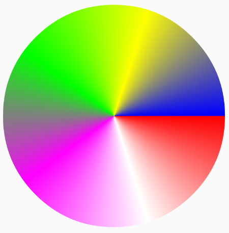
图5 SweepGradient 扫描梯度渲染效果
实现效果的主要代码:
	int w = getWidth();
	int h = getHeight();
	int raduis = w / 2 < h / 2 ? w / 2 : h / 2;
	// 梯度渐变 由1种颜色转变为另外一种颜色(2种颜色之间的转变)
	// mShader = new SweepGradient(w / 2, h / 2, Color.RED, Color.GREEN);
	// 梯度渐变 多种颜色之间的渐变
	mShader = new SweepGradient(w / 2, h / 2, new int[]{Color.RED, Color.WHITE, Color.MAGENTA, Color.GREEN, Color.YELLOW, Color.BLUE}, new float[]{0.0f, 0.2f, 0.4f, 0.6f, 0.8f, 1.0f});
	mPaint.setShader(mShader);
	canvas.drawCircle(w / 2, h / 2, raduis, mPaint);
ComposeShader 混合渲染
ComposeShader (Shader shaderA,
                Shader shaderB,
                Xfermode mode)
Create a new compose shader, given shaders A, B, and a combining mode. When the mode is applied, it will be given the result from shader A as its "dst", and the result from shader B as its "src".(创建一个新的合成着色器,给定着色器A,B和合并模式。 当应用该模式时,它将来自着色器A的结果作为其“dst”,并将来自着色器B的结果作为其“src”。)
如图6所示为BitmapShader和RadialGradient混合的渲染模式效果图。

int h = getHeight();
int w = getWidth();
int radius = w < h ? w / 2 : h / 2;
Bitmap bitmap = BitmapFactory.decodeResource(getResources(), R.mipmap.dog);
Bitmap result = Bitmap.createScaledBitmap(bitmap, w, h, false);
BitmapShader bitmapShader = new BitmapShader(result, Shader.TileMode.REPEAT, Shader.TileMode.REPEAT);
RadialGradient radialGradient = new RadialGradient(radius, radius, radius, Color.RED, Color.TRANSPARENT, Shader.TileMode.CLAMP);
ComposeShader composeShader = new ComposeShader(radialGradient, bitmapShader, PorterDuff.Mode.SRC_IN);
mPaint.setShader(composeShader);
canvas.drawCircle(w / 2, h / 2, radius, mPaint);
如图7所示为混合渲染是,外加了一个倒影效果
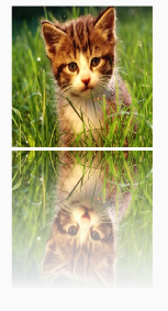
int bmpWidth = 200;
int bmpHeight = 200;
int gap = 5;
int reflectionHeight = bmpHeight ;
Bitmap bitmap = BitmapFactory.decodeResource(getResources(), R.mipmap.dog);
Bitmap result = Bitmap.createScaledBitmap(bitmap, bmpWidth, bmpHeight, false);
canvas.drawBitmap(result, 0, 0, null);
canvas.save();
//向下移动准备在原图下方绘制倒影
canvas.translate(0, bmpHeight + gap);
Matrix m = new Matrix();
m.postScale(-1f, 1f);
m.postRotate(-180);
Bitmap texture = Bitmap.createBitmap(result, 0, 0, result.getWidth(), result.getHeight(), m, false);
BitmapShader bitmapShader = new BitmapShader(texture, Shader.TileMode.REPEAT, Shader.TileMode.REPEAT);
LinearGradient linearGradient = new LinearGradient(0, 0, 0, reflectionHeight, Color.BLACK, Color.TRANSPARENT, Shader.TileMode.CLAMP);
ComposeShader composeShader = new ComposeShader(bitmapShader, linearGradient, PorterDuff.Mode.DST_IN);
mPaint.setShader(composeShader);
canvas.drawRect(0, 0, bmpWidth, reflectionHeight, mPaint);
canvas.restore();


 136
136


 被折叠的 条评论
为什么被折叠?
被折叠的 条评论
为什么被折叠?
 到【灌水乐园】发言


