


体绘制管线Imagedata->=VolumeMapper->Volume->Render->RenderWindow->RenderWindowInteractor
SetBlendModeToComposite()
Set/Get the blend mode.
The default mode is Composite where the scalar values are sampled through the volume and composited in a front-to-back scheme through alpha blending. The final color and opacity is determined using the color and opacity transfer functions.
Maximum and minimum intensity blend modes use the maximum and minimum scalar values, respectively, along the sampling ray. The final color and opacity is determined by passing the resultant value through the color and opacity transfer functions.
Additive blend mode accumulates scalar values by passing each value through the opacity transfer function and then adding up the product of the value and its opacity. In other words, the scalar values are scaled using the opacity transfer function and summed to derive the final color. Note that the resulting image is always grayscale i.e. aggregated values are not passed through the color transfer function. This is because the final value is a derived value and not a real data value along the sampling ray.
Average intensity blend mode works similar to the additive blend mode where the scalar values are multiplied by opacity calculated from the opacity transfer function and then added. The additional step here is to divide the sum by the number of samples taken through the volume. One can control the scalar range by setting the AverageIPScalarRange ivar to disregard scalar values, not in the range of interest, from the average computation. As is the case with the additive intensity projection, the final image will always be grayscale i.e. the aggregated values are not passed through the color transfer function. This is because the resultant value is a derived value and not a real data value along the sampling ray.
IsoSurface blend mode uses contour values defined by the user in order to display scalar values only when the ray crosses the contour. It supports opacity the same way composite blend mode does.
代码:
void MainWindow::ImageSliceTo3D(){
//生成图像序列的文件名数组
vtkSmartPointer <vtkStringArray> fileArray =
vtkSmartPointer <vtkStringArray>::New();
char fileName[128];
for(int i = 1; i < 100; i++)
{
sprintf(fileName, "VTK_test/Head/head%03d.jpg", i);
std::string fileStr(fileName);
fileArray->InsertNextValue(fileStr);
}
//读取JPG序列图像
vtkSmartPointer <vtkJPEGReader> reader = vtkSmartPointer<vtkJPEGReader>::New();
reader->SetFileNames(fileArray);
reader->Update();
vtkSmartPointer <vtkSmartVolumeMapper> volumeMapper=
vtkSmartPointer <vtkSmartVolumeMapper>::New();
volumeMapper->SetBlendModeToComposite();
volumeMapper->SetInputData(reader->GetOutput());
vtkSmartPointer <vtkVolumeProperty> volumeProperty=
vtkSmartPointer <vtkVolumeProperty>::New();
volumeProperty->ShadeOff();//关闭阴影
volumeProperty->SetInterpolationType(VTK_LINEAR_INTERPOLATION);
vtkSmartPointer <vtkPiecewiseFunction> compositeOpacity=
vtkSmartPointer <vtkPiecewiseFunction>::New();
compositeOpacity->AddPoint(0.0, 0);//设置像素值小于0的明度为0
compositeOpacity->AddPoint(255.0, 1.0);//设置像素值大于255的明度为1
volumeProperty->SetScalarOpacity(compositeOpacity);
vtkSmartPointer <vtkVolume> volume=
vtkSmartPointer <vtkVolume>::New();
volume->SetMapper(volumeMapper);
volume->SetProperty(volumeProperty);
vtkSmartPointer <vtkRenderer> render=vtkSmartPointer <vtkRenderer>::New();
render->SetBackground(0.1, 0.4, 0.2);
render->AddVolume(volume);
vtkSmartPointer <vtkRenderWindow> rw=vtkSmartPointer <vtkRenderWindow>::New();
rw->SetSize(512,512);
rw->AddRenderer(render);
vtkSmartPointer <vtkRenderWindowInteractor> rwi=vtkSmartPointer
<vtkRenderWindowInteractor>::New();
rwi->SetRenderWindow(rw);
rw->Render();
rwi->Initialize();
rwi->Start();
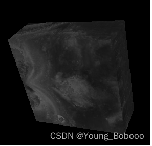
}效果:
参考链接:
 https://kitware.github.io/vtk-examples/site/Cxx/VolumeRendering/SmartVolumeMapper/
VTK 体绘制讨论_不透明度传输函数 - 一杯清酒邀明月 - 博客园 (cnblogs.com)![]() https://www.cnblogs.com/ybqjymy/p/14239936.html
https://www.cnblogs.com/ybqjymy/p/14239936.html


 676
676


 被折叠的 条评论
为什么被折叠?
被折叠的 条评论
为什么被折叠?
 到【灌水乐园】发言


