


尊重原创,转载请标明出处 http://blog.csdn.net/abcdef314159
在之前讲 Android Paint的使用详解的时候,其中有一个方法setPathEffect(PathEffect effect)没有详细介绍,这篇就结合代码来介绍一下,在之前说过PathEffect共有6个子类ComposePathEffect,CornerPathEffect,DashPathEffect,DiscretePathEffect,PathDashPathEffect,SumPathEffect,这些类代码量都很少,这里先一个个介绍
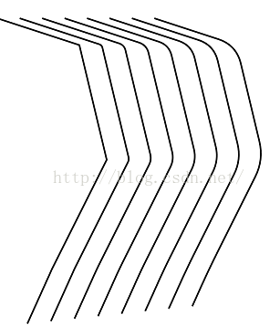
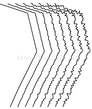
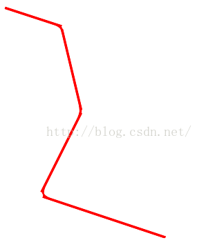
CornerPathEffect将Path的线段之间的夹角变成圆角。构造函数,其中radius为圆角的半径
    /**
     * Transforms geometries that are drawn (either STROKE or FILL styles) by
     * replacing any sharp angles between line segments into rounded angles of
     * the specified radius.
     * @param radius Amount to round sharp angles between line segments.
     */
    public CornerPathEffect(float radius) {
        native_instance = nativeCreate(radius);
    }
看一下代码
public class PathEffectView extends View {
	private Paint mPaint;
	private int marging = 82;
	private CornerPathEffect mCornerPathEffect[];
	private Path mPath[];

	public PathEffectView(Context context, AttributeSet attrs) {
		super(context, attrs);
		init();
	}

	private void init() {
		mPaint = new Paint(Paint.ANTI_ALIAS_FLAG);
		mPaint.setColor(Color.BLACK);
		mPaint.setStyle(Style.STROKE);
		mPaint.setStrokeWidth(6);
		mCornerPathEffect = new CornerPathEffect[8];
		mPath = new Path[8];
		for (int i = 0; i < mPath.length; i++) {
			Path path = new Path();
			path.moveTo(i * marging, marging);
			path.lineTo(300 + i * marging, 180);
			path.lineTo(400 + i * marging, 600);
			path.lineTo(200 + i * marging, 1000);
			path.lineTo(110 + i * marging, 1200);
			mPath[i] = path;
			mCornerPathEffect[i] = new CornerPathEffect(i * 10);
		}
	}

	@Override
	protected void onDraw(Canvas canvas) {
		super.onDraw(canvas);
		canvas.drawColor(Color.WHITE);
		for (int i = 0; i < mPath.length; i++) {
			mPaint.setPathEffect(mCornerPathEffect[i]);
			canvas.drawPath(mPath[i], mPaint);
		}
	}
}
/**
* The intervals array must contain an even number of entries (>=2), with
* the even indices specifying the "on" intervals, and the odd indices
* specifying the "off" intervals. phase is an offset into the intervals
* array (mod the sum of all of the intervals). The intervals array
* controls the length of the dashes. The paint's strokeWidth controls the
* thickness of the dashes.
* Note: this patheffect only affects drawing with the paint's style is set
* to STROKE or FILL_AND_STROKE. It is ignored if the drawing is done with
* style == FILL.
* @param intervals array of ON and OFF distances
* @param phase offset into the intervals array
*/
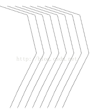
public DashPathEffect(float intervals[], float phase) {
if (intervals.length < 2) {
throw new ArrayIndexOutOfBoundsException();
}
native_instance = nativeCreate(intervals, phase);
}看一下代码
public class PathEffectView extends View {
	private Paint mPaint;
	private int marging = 82;
	private DashPathEffect mCornerPathEffect[];
	private Path mPath[];

	public PathEffectView(Context context, AttributeSet attrs) {
		super(context, attrs);
		init();
	}

	private void init() {
		mPaint = new Paint(Paint.ANTI_ALIAS_FLAG);
		mPaint.setColor(Color.BLACK);
		mPaint.setStyle(Style.STROKE);
		mPaint.setStrokeWidth(6);
		mCornerPathEffect = new DashPathEffect[8];
		mPath = new Path[8];
		for (int i = 0; i < mPath.length; i++) {
			Path path = new Path();
			path.moveTo(i * marging, marging);
			path.lineTo(300 + i * marging, 180);
			path.lineTo(400 + i * marging, 600);
			path.lineTo(200 + i * marging, 1000);
			path.lineTo(110 + i * marging, 1200);
			mPath[i] = path;
			mCornerPathEffect[i] = new DashPathEffect(
					new float[] { 1, 2, 4, 8 }, 1);
		}
	}

	@Override
	protected void onDraw(Canvas canvas) {
		super.onDraw(canvas);
		canvas.drawColor(Color.WHITE);
		for (int i = 0; i < mPath.length; i++) {
			mPaint.setPathEffect(mCornerPathEffect[i]);
			canvas.drawPath(mPath[i], mPaint);
		}
	}
}
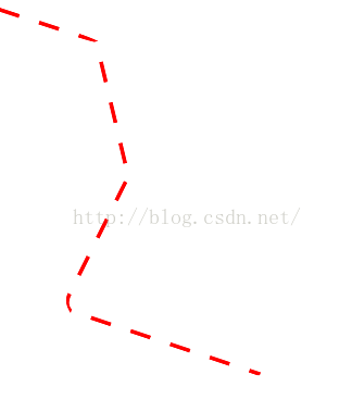
这里phase的偏移量是指偏移指定长度的位置开始画,但总长度还是不变,我们改一下再看看
			mCornerPathEffect[i] = new DashPathEffect(new float[] { 10, 20, 40,
					80 }, i * 10);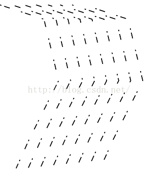
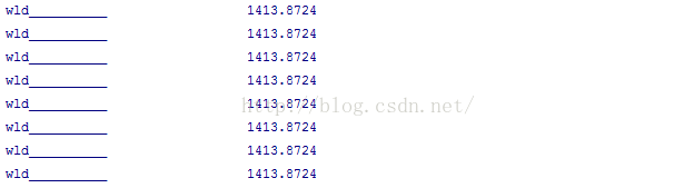
先画长度为10的实线,再画长度为20的虚线,接着画长度为40的实线,最后画长度为80的虚线,看一下起始位置,每次的最开始都不一样,因为每次偏移的都不一样,但总长度是不变的,因为上面的线只是左右平移,长度并没有减少,看到上面的线是越来越短,其实这是一种巧合,因为后面到虚线了,看不到了。通俗一点来说就是,线的开始位置和终止位置都没有改变,线就像一个无限长的绳,偏移量就相当于绳往下(后)拽的距离。我们打印看一下长度就知道了,修改一下
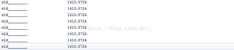
		for (int i = 0; i < mPath.length; i++) {
			mPaint.setPathEffect(mCornerPathEffect[i]);
			canvas.drawPath(mPath[i], mPaint);
			PathMeasure measure = new PathMeasure(mPath[i], false);
			Log.d("wld_________", measure.getLength() + "");
		}
DiscretePathEffect切断线段,segmentLength是指定切断的长度,deviation为切断之后线段的偏移量,随机的,小于等于deviation。
    /**
     * Chop the path into lines of segmentLength, randomly deviating from the
     * original path by deviation.
     */
    public DiscretePathEffect(float segmentLength, float deviation) {
        native_instance = nativeCreate(segmentLength, deviation);
}public class PathEffectView extends View {
private Paint mPaint;
private int marging = 82;
private DiscretePathEffect mPathEffect[];
private Path mPath[];
public PathEffectView(Context context, AttributeSet attrs) {
super(context, attrs);
init();
}
private void init() {
mPaint = new Paint(Paint.ANTI_ALIAS_FLAG);
mPaint.setColor(Color.BLACK);
mPaint.setStyle(Style.STROKE);
mPaint.setStrokeWidth(6);
mPathEffect = new DiscretePathEffect[8];
mPath = new Path[8];
for (int i = 0; i < mPath.length; i++) {
Path path = new Path();
path.moveTo(i * marging, marging);
path.lineTo(300 + i * marging, 180);
path.lineTo(400 + i * marging, 600);
path.lineTo(200 + i * marging, 1000);
path.lineTo(110 + i * marging, 1200);
mPath[i] = path;
mPathEffect[i] = new DiscretePathEffect(10, 3 * i);
}
}
@Override
protected void onDraw(Canvas canvas) {
super.onDraw(canvas);
canvas.drawColor(Color.WHITE);
for (int i = 0; i < mPath.length; i++) {
mPaint.setPathEffect(mPathEffect[i]);
canvas.drawPath(mPath[i], mPaint);
}
}
}运行结果
mPathEffect[i] = new DiscretePathEffect(1, 3 * i);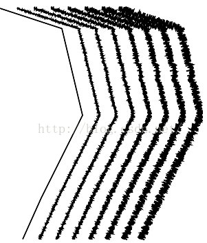
感觉有点像磁铁一样,我们来测量一下他的长度
for (int i = 0; i < mPath.length; i++) {
			mPaint.setPathEffect(mPathEffect[i]);
			canvas.drawPath(mPath[i], mPaint);
			PathMeasure measure = new PathMeasure(mPath[i], false);
			Log.d("wld__________", measure.getLength() + "");
		}
不可思议,每个长度都一样,还和之前测的一样,一点都没变。
    public enum Style {
        TRANSLATE(0),   //!< translate the shape to each position
        ROTATE(1),      //!< rotate the shape about its center
        MORPH(2);       //!< transform each point, and turn lines into curves

        Style(int value) {
            native_style = value;
        }
        int native_style;
    }

    /**
     * Dash the drawn path by stamping it with the specified shape. This only
     * applies to drawings when the paint's style is STROKE or STROKE_AND_FILL.
     * If the paint's style is FILL, then this effect is ignored. The paint's
     * strokeWidth does not affect the results.
     * @param shape The path to stamp along
     * @param advance spacing between each stamp of shape
     * @param phase amount to offset before the first shape is stamped
     * @param style how to transform the shape at each position as it is stamped
     */
    public PathDashPathEffect(Path shape, float advance, float phase,
                              Style style) {
        native_instance = nativeCreate(shape.ni(), advance, phase,
                                       style.native_style);
    }

    private static native long nativeCreate(long native_path, float advance,
                                           float phase, int native_style);
public class PathEffectView extends View {
	private Paint mPaint;
	private int marging = 82;
	private PathEffect mPathEffect1;
	private PathEffect mPathEffect2;
	private PathEffect mPathEffect3;
	private Path mPath;

	public PathEffectView(Context context, AttributeSet attrs) {
		super(context, attrs);
		init();
	}

	private void init() {
		mPaint = new Paint(Paint.ANTI_ALIAS_FLAG);
		mPaint.setStyle(Style.STROKE);
		mPaint.setStrokeWidth(6);
		mPaint.setColor(Color.RED);
		mPath = new Path();
		mPath.moveTo(0, marging);
		mPath.lineTo(300, 180);
		mPath.lineTo(400, 600);
		mPath.lineTo(200, 1000);
		mPath.lineTo(800, 1200);
		Path p = new Path();
		p.addRect(0, 0, 64, 12, Path.Direction.CCW);
		mPathEffect1 = new PathDashPathEffect(p, 128, 0,
				android.graphics.PathDashPathEffect.Style.MORPH);
		mPathEffect2 = new PathDashPathEffect(p, 128, 0,
				android.graphics.PathDashPathEffect.Style.ROTATE);
		mPathEffect3 = new PathDashPathEffect(p, 128, 0,
				android.graphics.PathDashPathEffect.Style.TRANSLATE);
	}

	@Override
	protected void onDraw(Canvas canvas) {
		super.onDraw(canvas);
		canvas.drawColor(Color.WHITE);
		mPaint.setPathEffect(mPathEffect1);
		canvas.drawPath(mPath, mPaint);
		canvas.translate(200, 0);
		mPaint.setPathEffect(mPathEffect2);
		canvas.drawPath(mPath, mPaint);
		canvas.translate(200, 0);
		mPaint.setPathEffect(mPathEffect3);
		canvas.drawPath(mPath, mPaint);
	}
}
看一下运行效果,
		mPathEffect1 = new PathDashPathEffect(p, 0, 0,
				android.graphics.PathDashPathEffect.Style.MORPH);
		mPathEffect2 = new PathDashPathEffect(p, 64, 0,
				android.graphics.PathDashPathEffect.Style.MORPH);
		mPathEffect3 = new PathDashPathEffect(p, 228, 0,
				android.graphics.PathDashPathEffect.Style.MORPH);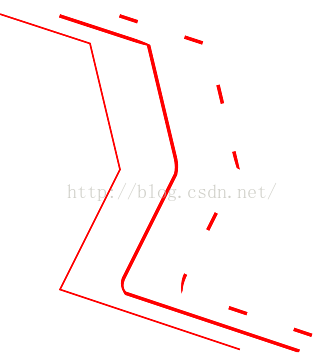
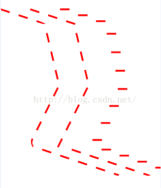
第一个是没有间距的,第二个间距等于矩形的宽度,所以正好相当于矩形首尾相连中间没有间隙,最后一个有间隙。再看第三个参数,就是偏移量,这个和第二个参数有关,在1到advance中间时,偏移的距离在逐渐减少,当偏移量等于advance的倍数的时候,偏移的距离为0,当偏移量大于advance的时候,会对他求余。我们看一下代码
	private void init() {
		mPaint = new Paint(Paint.ANTI_ALIAS_FLAG);
		mPaint.setStyle(Style.STROKE);
		mPaint.setStrokeWidth(6);
		mPaint.setColor(Color.RED);
		mPath = new Path();
		mPath.moveTo(0, marging);
		mPath.lineTo(300, 180);
		mPath.lineTo(400, 600);
		mPath.lineTo(200, 1000);
		mPath.lineTo(800, 1200);
		Path p = new Path();
		p.addRect(0, 0, 64, 12, Path.Direction.CCW);
		mPathEffect1 = new PathDashPathEffect(p, 128, 128,
				android.graphics.PathDashPathEffect.Style.MORPH);
	}

	@Override
	protected void onDraw(Canvas canvas) {
		super.onDraw(canvas);
		canvas.drawColor(Color.WHITE);
		mPaint.setPathEffect(mPathEffect1);
		canvas.drawPath(mPath, mPaint);
	}
看一下运行结果
		mPathEffect1 = new PathDashPathEffect(p, 128, 129,
				android.graphics.PathDashPathEffect.Style.MORPH);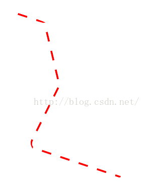
我们看到偏移量已经达到最大,其实129和1的结果是一样的,因为129对128求余所得结果也是1,偏移量从1到128逐渐增大时,偏移的距离逐渐减少,且当偏移量为128时则没有偏移。再来改一下代码
		mPathEffect1 = new PathDashPathEffect(p, 28, 1,
				android.graphics.PathDashPathEffect.Style.MORPH);
当把代码在改一下的时候
		mPathEffect1 = new PathDashPathEffect(p, 28, 28,
android.graphics.PathDashPathEffect.Style.MORPH);ComposePathEffect是一种组合模式,把两种path所具有的特性组合起来,先看一下源码
    /**
     * Construct a PathEffect whose effect is to apply first the inner effect
     * and the the outer pathEffect (e.g. outer(inner(path))).
     */
    public ComposePathEffect(PathEffect outerpe, PathEffect innerpe) {
        native_instance = nativeCreate(outerpe.native_instance,
                                       innerpe.native_instance);
    }

    private static native long nativeCreate(long nativeOuterpe,
long nativeInnerpe);public class PathEffectView extends View {
private Paint mPaint;
private int marging = 82;
private PathEffect mEffects[];
private Path mPath;
public PathEffectView(Context context, AttributeSet attrs) {
super(context, attrs);
init();
}
private void init() {
mPaint = new Paint(Paint.ANTI_ALIAS_FLAG);
mPaint.setStyle(Style.STROKE);
mPaint.setStrokeWidth(6);
mPaint.setColor(Color.RED);
mPath = new Path();
mPath.moveTo(0, marging);
mPath.lineTo(300, 180);
mPath.lineTo(400, 600);
mPath.lineTo(200, 1000);
mPath.lineTo(800, 1200);
Path p = new Path();
p.addRect(0, 0, 64, 12, Path.Direction.CCW);
mEffects = new PathEffect[3];
mEffects[0] = new CornerPathEffect(80);
mEffects[1] = new DashPathEffect(new float[] { 20, 10, 5, 10 }, 0);
mEffects[2] = new ComposePathEffect(mEffects[1], mEffects[0]);
}
@Override
protected void onDraw(Canvas canvas) {
super.onDraw(canvas);
for (int i = 0; i < mEffects.length; i++) {
mPaint.setPathEffect(mEffects[i]);
canvas.drawPath(mPath, mPaint);
canvas.translate(200, 0);
}
}
}
第一个是圆角的,第二个是虚线的,所以组合的第三个就是圆角到虚线的。在修改一下代码,调换一下组合的位置,
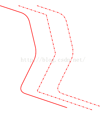
mEffects[2] = new ComposePathEffect(mEffects[0], mEffects[1]);看一下运行结果
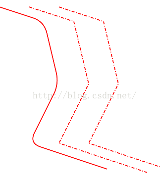
我们看到组合模式基本上没变,这是因为我们先提取的是第二个图的效果,再提取的是第一个的,所以看不到上面效果,我们在改一下代码
mEffects[1] = new DashPathEffect(new float[] { 200, 10, 5, 10 }, 0);
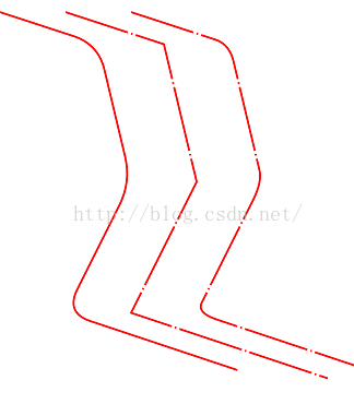
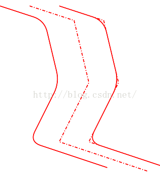
OK,我们再来看最后一种SumPathEffect,他相当于把两种效果分别展示然后再组合在一起。还是用上面的代码简单的修改一下
		mEffects[1] = new DashPathEffect(new float[] { 20, 10, 5, 10 }, 0);
		mEffects[2] = new SumPathEffect(mEffects[1], mEffects[0]);
OK,到目前为止,PathEffect的6种效果全部分析完毕。当然,如果想制作动态的效果,可以在onDraw方法中调用invalidate()方法,然后不停的修改偏移量就行了。


 513
513

 被折叠的 条评论
为什么被折叠?
被折叠的 条评论
为什么被折叠?
 到【灌水乐园】发言


