


文章目录
前言
本博客主要记录自己学习STM32H7xxx系列的GPIO模块,深入学习源代码,希望和大家一起讨论学习与交流,如有更好的意见欢迎大家提出,学习思考
1、stm32h7xx_hal_gpio.c
这个文件主要hal库函数,是实现GPIO的引脚配置,学习这个文件注意事项:
◆ 系统上电后,引脚默认状态是模拟模式。
◆ 所有的引脚有弱上拉和弱下拉电阻,阻值范围30-50KΩ。其中配置为模拟模式时,上拉和下拉被硬件禁止,其它的输入、输出和复用都可以配置上拉和下拉。
◆ 在输出或者复用模式,每个引脚可以配置成推挽或者开漏,且有GPIO速度等级可配置。另外注意,不同的供电范围,实际速度等级是有些区别的。
◆ 每个GPIO都可以配置成外部中断/事件模式,但要特别注意,引脚要配置成输入模式,在芯片的内部有个多路选择器,选择引脚与16个外部中断/事件EXTI0 - EXTI15中的那个导通。这就决定了,每个外部中断/事件只能与一个引脚导通,如果用户配置了多个引脚PA0,PB0,PC0等,那么只有一个能够与EXTI0导通。
1.1、函数 HAL_GPIO_Init()
/**
  * @brief  Initializes the GPIOx peripheral according to the specified parameters in the GPIO_Init.
  * @param  GPIOx: where x can be (A..K) to select the GPIO peripheral.
  * @param  GPIO_Init: pointer to a GPIO_InitTypeDef structure that contains
  *         the configuration information for the specified GPIO peripheral.
  * @retval None


   HAL_GPIO_Init(LED_PORT [Led], &gpio_init_structure);
  LED1_GPIO_PORT==>GPIOF==>(SRD_AHB4PERIPH_BASE + 0x1400UL)
     =(PERIPH_BASE + 0x18020000UL)+ 0x1400UL
     =(0x40000000UL+ 0x18020000UL)+ 0x1400UL
     =0x58021400UL
LED1_PIN==>GPIO_PIN_10==>((uint16_t)0x0400)
gpio_init_structure.Mode = GPIO_MODE_OUTPUT_PP   ==>0x00000001U
gpio_init_structure.Pull = GPIO_PULLUP;          ==>0x00000001U
gpio_init_structure.Speed = GPIO_SPEED_FREQ_HIGH ==>0x00000002U
gpio_init_structure.Pin = LED_PIN [Led];         ==>0x0400
                                                    0000 0100 0000 0000
  */
void HAL_GPIO_Init(GPIO_TypeDef  *GPIOx, GPIO_InitTypeDef *GPIO_Init)
{
  uint32_t position = 0x00U;
  uint32_t iocurrent;
  uint32_t temp;
  EXTI_Core_TypeDef *EXTI_CurrentCPU;

#if defined(DUAL_CORE) && defined(CORE_CM4)
  EXTI_CurrentCPU = EXTI_D2; /* EXTI for CM4 CPU */
#else
  EXTI_CurrentCPU = EXTI_D1; /* EXTI for CM7 CPU */
#endif

  /* Check the parameters */
    /*断言的作用,如果宏没有开启,这句话就是0,基本不会执行,如果宏开启了,需要自己在对应的
    文件中加入打印输出,用于调试*/
  assert_param(IS_GPIO_ALL_INSTANCE(GPIOx));
  assert_param(IS_GPIO_PIN(GPIO_Init->Pin));
  assert_param(IS_GPIO_MODE(GPIO_Init->Mode));
  assert_param(IS_GPIO_PULL(GPIO_Init->Pull));

  /* Configure the port pins */
  while (((GPIO_Init->Pin) >> position) != 0x00U)/*position从0加到对应的pin值位置*/
  {
    /* Get current io position */
    iocurrent = (GPIO_Init->Pin) & (1UL << position);
              //0x00000400  当position为11的时候,iocurrent才等于1,此时下面的IF语句才会成立进入

    if (iocurrent != 0x00U)
    {
      /*--------------------- GPIO Mode Configuration ------------------------*/
      /* In case of Output or Alternate function mode selection */
      if ((GPIO_Init->Mode == GPIO_MODE_OUTPUT_PP) || (GPIO_Init->Mode == GPIO_MODE_AF_PP) ||
          (GPIO_Init->Mode == GPIO_MODE_OUTPUT_OD) || (GPIO_Init->Mode == GPIO_MODE_AF_OD))
      {
        /* Check the Speed parameter */
        assert_param(IS_GPIO_SPEED(GPIO_Init->Speed));

        /* 1. Configure the IO Speed 设置IO口的速度*/
        temp = GPIOx->OSPEEDR;  //GPIOF->OSPEEDR = 0x0000 0000

          /*GPIO_OSPEEDR_OSPEED0 = 0x0000 0003
          position * 2U = 22
          (GPIO_OSPEEDR_OSPEED0 << (position * 2U) = 0x00c00000
          ~(GPIO_OSPEEDR_OSPEED0 << (position * 2U) = 0xff3fffff
          temp= 0 */
        temp &= ~(GPIO_OSPEEDR_OSPEED0 << (position * 2U));  //把对应位置的全部置0

          /*GPIO_Init->Speed = 0x00000002U
          GPIO_Init->Speed << (position * 2U) = 0x00800000
          temp= 0x00800000*/
        temp |= (GPIO_Init->Speed << (position * 2U));  //把对应位置的全部置1
/*将temp当前的值0x0C00 0000与0xFFFF F3FF相“与”,结果为0x0C00 0000,该值会赋给temp。
所以该语句执行完毕后,temp的值为0x0C00 0000。
这个结果与OSPEED寄存器的默认值相比较,在数值上没有什么变化。做这些操作有何意义呢?

实际上,这两个temp赋值语句的目的是,将OSPEED寄存器中要配置的相应位(对PA5来说就是第10和11位)
变为00,以便接下来做修改。这里与默认值相同的原因是,在此次读取OSPEED寄存器的时刻,
这两位本来就为00*/
        GPIOx->OSPEEDR = temp;  //GPIOx->OSPEEDR =0x00800000对应的就是在OSPEEDR11的
                                //位置设置成01,对应的是高速

        /* 2. Configure the IO Output Type 设置IO口的输出类型*/
        temp = GPIOx->OTYPER;// GPIOx->OTYPER = 0x0000 0000,只有[15:0]可以读写

          /* GPIO_OTYPER_OT0 = 0x00000001
          GPIO_OTYPER_OT0 << position = 0x0000 0800
           ~(GPIO_OTYPER_OT0 << position) = 0xffff f7ff
           temp = 0
          */
        temp &= ~(GPIO_OTYPER_OT0 << position) ;

          /*(GPIO_Init->Mode & GPIO_OUTPUT_TYPE) = 0x00000001 & 0x00000010
          temp = 0
          */
        temp |= (((GPIO_Init->Mode & GPIO_OUTPUT_TYPE) >> 4U) << position);
        GPIOx->OTYPER = temp;// GPIOx->OTYPER = 0x00000000对应的设置位推完输出
      }

      /* 3. Activate the Pull-up or Pull down resistor for the current IO
        设置上拉、下拉*/
      temp = GPIOx->PUPDR;  // GPIOF->PUPDR = 0x0000 0000

        /* GPIO_PUPDR_PUPD0 = 0x0000 0003

        */
      temp &= ~(GPIO_PUPDR_PUPD0 << (position * 2U));
      temp |= ((GPIO_Init->Pull) << (position * 2U));
      GPIOx->PUPDR = temp;  //GPIOx->PUPDR = 0x0040 0000对应位置设置成上拉

      /* In case of Alternate function mode selection */
      if ((GPIO_Init->Mode == GPIO_MODE_AF_PP) || (GPIO_Init->Mode == GPIO_MODE_AF_OD))
      {
        /* Check the Alternate function parameters */
        assert_param(IS_GPIO_AF_INSTANCE(GPIOx));
        assert_param(IS_GPIO_AF(GPIO_Init->Alternate));

        /* 4. Configure Alternate function mapped with the current IO
          设置复用功能*/
        temp = GPIOx->AFR[position >> 3U];//GPIOx->AFR[1] = 0x0000 0000

          /*0xFU << ((position & 0x07U) * 4U) = 0xf000
          temp = 0x0000 0000*/
        temp &= ~(0xFU << ((position & 0x07U) * 4U));
        temp |= ((GPIO_Init->Alternate) << ((position & 0x07U) * 4U));
        GPIOx->AFR[position >> 3U] = temp;
      }

      /* 5. Configure IO Direction mode (Input, Output, Alternate or Analog)
        设置IO口方向模式(输入、输出、复用、模拟)*/
      temp = GPIOx->MODER;
      temp &= ~(GPIO_MODER_MODE0 << (position * 2U));
      temp |= ((GPIO_Init->Mode & GPIO_MODE) << (position * 2U));
      GPIOx->MODER = temp;

      /*--------------------- EXTI Mode Configuration ------------------------*/
      /* Configure the External Interrupt or event for the current IO */
        /*
//#define  GPIO_MODE_IT_RISING                    (0x11110000U)   /*!< External Interrupt Mode with Rising edge trigger detection          */
//#define  GPIO_MODE_IT_FALLING                   (0x11210000U)   /*!< External Interrupt Mode with Falling edge trigger detection         */
//#define  GPIO_MODE_IT_RISING_FALLING            (0x11310000U)   /*!< External Interrupt Mode with Rising/Falling edge trigger detection  */
        //可以看出中断模式下的都是0x11000000开头的,而 EXTI_MODE=(0x10000000U)
      if ((GPIO_Init->Mode & EXTI_MODE) == EXTI_MODE)
      {
        /* Enable SYSCFG Clock */
        __HAL_RCC_SYSCFG_CLK_ENABLE();

        temp = SYSCFG->EXTICR[position >> 2U];
        temp &= ~(0x0FUL << (4U * (position & 0x03U)));
        temp |= (GPIO_GET_INDEX(GPIOx) << (4U * (position & 0x03U)));
        SYSCFG->EXTICR[position >> 2U] = temp;

        /* Clear EXTI line configuration */
        temp = EXTI_CurrentCPU->IMR1;
        temp &= ~(iocurrent);
        if ((GPIO_Init->Mode & GPIO_MODE_IT) == GPIO_MODE_IT)
        {
          temp |= iocurrent;
        }
        EXTI_CurrentCPU->IMR1 = temp;

        temp = EXTI_CurrentCPU->EMR1;
        temp &= ~(iocurrent);
        if ((GPIO_Init->Mode & GPIO_MODE_EVT) == GPIO_MODE_EVT)
        {
          temp |= iocurrent;
        }
        EXTI_CurrentCPU->EMR1 = temp;

        /* Clear Rising Falling edge configuration */
        temp = EXTI->RTSR1;
        temp &= ~(iocurrent);
        if ((GPIO_Init->Mode & RISING_EDGE) == RISING_EDGE)
        {
          temp |= iocurrent;
        }
        EXTI->RTSR1 = temp;

        temp = EXTI->FTSR1;
        temp &= ~(iocurrent);
        if ((GPIO_Init->Mode & FALLING_EDGE) == FALLING_EDGE)
        {
          temp |= iocurrent;
        }
        EXTI->FTSR1 = temp;
      }
    }

    position++;
  }
}
1.1.1 函数描述
此函数用于初始化GPIO,此函数主要实现如下功能:
- ◆ GPIO功能配置。
- 设置IO口的速度
- 设置IO口的输出类型
- 设置IO口上拉、下拉
- 设置IO口复用功能
- 设置IO口方向模式(输入、输出、复用、模拟)
- ◆ 设置EXTI功能。
1.1.2 函数参数
◆ 第1个参数用于填写使用的端口号,可以是:
#define GPIOA               ((GPIO_TypeDef *) GPIOA_BASE)
#define GPIOB               ((GPIO_TypeDef *) GPIOB_BASE)
#define GPIOC               ((GPIO_TypeDef *) GPIOC_BASE)
#define GPIOD               ((GPIO_TypeDef *) GPIOD_BASE)
#define GPIOE               ((GPIO_TypeDef *) GPIOE_BASE)
#define GPIOF               ((GPIO_TypeDef *) GPIOF_BASE)
#define GPIOG               ((GPIO_TypeDef *) GPIOG_BASE)
#define GPIOH               ((GPIO_TypeDef *) GPIOH_BASE)
#define GPIOI               ((GPIO_TypeDef *) GPIOI_BASE)
#define GPIOJ               ((GPIO_TypeDef *) GPIOJ_BASE)
#define GPIOK               ((GPIO_TypeDef *) GPIOK_BASE)

**************************************************************************
/*!< SRD_AHB4PERIPH peripherals */
#define GPIOA_BASE            (SRD_AHB4PERIPH_BASE + 0x0000UL)
#define GPIOB_BASE            (SRD_AHB4PERIPH_BASE + 0x0400UL)
#define GPIOC_BASE            (SRD_AHB4PERIPH_BASE + 0x0800UL)
#define GPIOD_BASE            (SRD_AHB4PERIPH_BASE + 0x0C00UL)
#define GPIOE_BASE            (SRD_AHB4PERIPH_BASE + 0x1000UL)
#define GPIOF_BASE            (SRD_AHB4PERIPH_BASE + 0x1400UL)
#define GPIOG_BASE            (SRD_AHB4PERIPH_BASE + 0x1800UL)
#define GPIOH_BASE            (SRD_AHB4PERIPH_BASE + 0x1C00UL)
#define GPIOI_BASE            (SRD_AHB4PERIPH_BASE + 0x2000UL)
#define GPIOJ_BASE            (SRD_AHB4PERIPH_BASE + 0x2400UL)
#define GPIOK_BASE            (SRD_AHB4PERIPH_BASE + 0x2800UL)
***************************************************************************

***************************************************************************
#define SRD_APB4PERIPH_BASE      (PERIPH_BASE + 0x18000000UL)   /*!<  D3_APB1PERIPH_BASE       (PERIPH_BASE + 0x18000000UL)                    */
#define SRD_AHB4PERIPH_BASE      (PERIPH_BASE + 0x18020000UL)   /*!<  D3_AHB1PERIPH_BASE       (PERIPH_BASE + 0x18020000UL)                    */
***************************************************************************

***************************************************************************
#define PERIPH_BASE               (0x40000000UL) /*!< Base address of : AHB/ABP Peripherals                                                    */
1.1.3 GPIO类型结构体–GPIO_TypeDef
**************************************************************************************************
#ifdef __cplusplus
#define __I volatile /*!< Defines 'read only' permissions */
#else
#define __I volatile const /*!< Defines 'read only' permissions */
#endif
#define __O volatile /*!< Defines 'write only' permissions */
#define __IO volatile /*!< Defines 'read / write' permissions */
/* following defines should be used for structure members */
#define __IM volatile const /*! Defines 'read only' structure member permissions */
#define __OM volatile /*! Defines 'write only' structure member permissions */
#define __IOM volatile /*! Defines 'read / write' structure member permissions */
***************************************************************************************************
typedef struct
{
__IO uint32_t MODER; /*!< GPIO port mode register, Address offset: 0x00 */
__IO uint32_t OTYPER; /*!< GPIO port output type register, Address offset: 0x04 */
__IO uint32_t OSPEEDR; /*!< GPIO port output speed register, Address offset: 0x08 */
__IO uint32_t PUPDR; /*!< GPIO port pull-up/pull-down register, Address offset: 0x0C */
__IO uint32_t IDR; /*!< GPIO port input data register, Address offset: 0x10 */
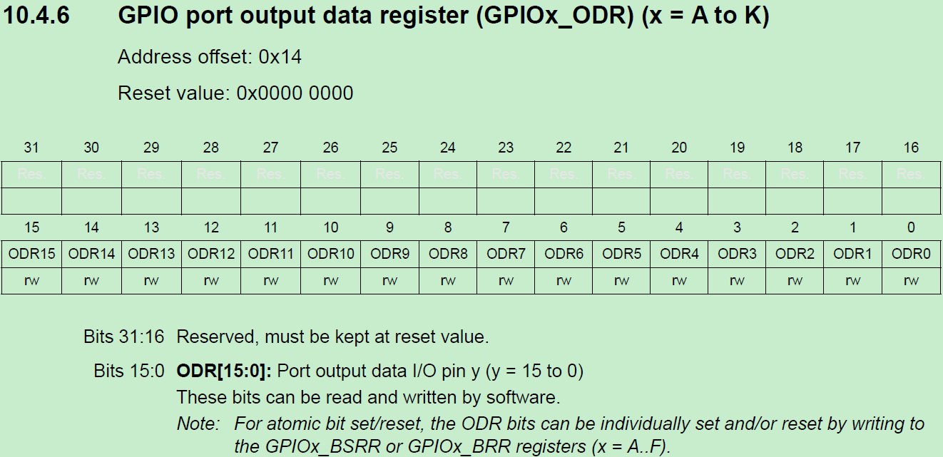
__IO uint32_t ODR; /*!< GPIO port output data register, Address offset: 0x14 */
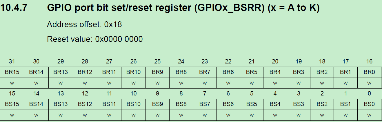
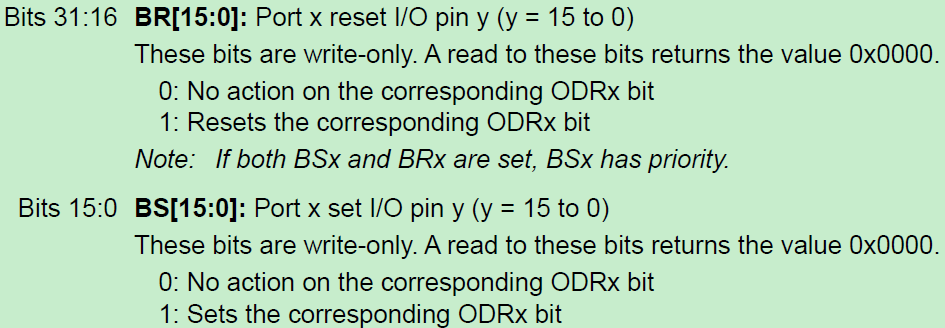
__IO uint32_t BSRR; /*!< GPIO port bit set/reset, Address offset: 0x18 */
__IO uint32_t LCKR; /*!< GPIO port configuration lock register, Address offset: 0x1C */
__IO uint32_t AFR[2]; /*!< GPIO alternate function registers, Address offset: 0x20-0x24 */
} GPIO_TypeDef;
GPIO类型结构体中包含了:GPIO口模式寄存器、输出类型寄存器、输出速度寄存器、上拉与下拉、输入数据、输出数据、设置位与复位、设置时钟、复用功能
1.1.4 GPIO初始化结构体–GPIO_InitTypeDef
/**
  * @brief   GPIO Init structure definition
  */
typedef struct
{
  uint32_t Pin;       /*!< Specifies the GPIO pins to be configured.
                           This parameter can be any value of @ref GPIO_pins_define */

  uint32_t Mode;      /*!< Specifies the operating mode for the selected pins.
                           This parameter can be a value of @ref GPIO_mode_define */

  uint32_t Pull;      /*!< Specifies the Pull-up or Pull-Down activation for the selected pins.
                           This parameter can be a value of @ref GPIO_pull_define */

  uint32_t Speed;     /*!< Specifies the speed for the selected pins.
                           This parameter can be a value of @ref GPIO_speed_define */

  uint32_t Alternate;  /*!< Peripheral to be connected to the selected pins.
                            This parameter can be a value of @ref GPIO_Alternate_function_selection */
} GPIO_InitTypeDef;
下面将结构体每个成员做个说明:
- 成员pin用于配置选择的引脚
范围GPIO_PIN_0到GPIO_PIN_15,额外还可以选择GPIO_PIN_All和GPIO_PIN_MASK。
/** @defgroup GPIO_pins_define  GPIO pins define
  * @{
  */
#define GPIO_PIN_0                 ((uint16_t)0x0001)  /* Pin 0 selected    */
#define GPIO_PIN_1                 ((uint16_t)0x0002)  /* Pin 1 selected    */
#define GPIO_PIN_2                 ((uint16_t)0x0004)  /* Pin 2 selected    */
#define GPIO_PIN_3                 ((uint16_t)0x0008)  /* Pin 3 selected    */
#define GPIO_PIN_4                 ((uint16_t)0x0010)  /* Pin 4 selected    */
#define GPIO_PIN_5                 ((uint16_t)0x0020)  /* Pin 5 selected    */
#define GPIO_PIN_6                 ((uint16_t)0x0040)  /* Pin 6 selected    */
#define GPIO_PIN_7                 ((uint16_t)0x0080)  /* Pin 7 selected    */
#define GPIO_PIN_8                 ((uint16_t)0x0100)  /* Pin 8 selected    */
#define GPIO_PIN_9                 ((uint16_t)0x0200)  /* Pin 9 selected    */
#define GPIO_PIN_10                ((uint16_t)0x0400)  /* Pin 10 selected   */
#define GPIO_PIN_11                ((uint16_t)0x0800)  /* Pin 11 selected   */
#define GPIO_PIN_12                ((uint16_t)0x1000)  /* Pin 12 selected   */
#define GPIO_PIN_13                ((uint16_t)0x2000)  /* Pin 13 selected   */
#define GPIO_PIN_14                ((uint16_t)0x4000)  /* Pin 14 selected   */
#define GPIO_PIN_15                ((uint16_t)0x8000)  /* Pin 15 selected   */
#define GPIO_PIN_All               ((uint16_t)0xFFFF)  /* All pins selected */

#define GPIO_PIN_MASK              (0x0000FFFFU) /* PIN mask for assert test */
- 成员mode可以选择:
/** @defgroup GPIO_mode_define  GPIO mode define
  * @brief GPIO Configuration Mode
  *        Elements values convention: 0xX0yz00YZ
  *           - X  : GPIO mode or EXTI Mode
  *           - y  : External IT or Event trigger detection
  *           - z  : IO configuration on External IT or Event
  *           - Y  : Output type (Push Pull or Open Drain)
  *           - Z  : IO Direction mode (Input, Output, Alternate or Analog)
  * @{
  */
#define  GPIO_MODE_INPUT                        (0x00000000U)   /*!< Input Floating Mode                   */
#define  GPIO_MODE_OUTPUT_PP                    (0x00000001U)   /*!< Output Push Pull Mode                 */
#define  GPIO_MODE_OUTPUT_OD                    (0x00000011U)   /*!< Output Open Drain Mode                */
#define  GPIO_MODE_AF_PP                        (0x00000002U)   /*!< Alternate Function Push Pull Mode     */
#define  GPIO_MODE_AF_OD                        (0x00000012U)   /*!< Alternate Function Open Drain Mode    */

#define  GPIO_MODE_ANALOG                       (0x00000003U)   /*!< Analog Mode  */

#define  GPIO_MODE_IT_RISING                    (0x11110000U)   /*!< External Interrupt Mode with Rising edge trigger detection          */
#define  GPIO_MODE_IT_FALLING                   (0x11210000U)   /*!< External Interrupt Mode with Falling edge trigger detection         */
#define  GPIO_MODE_IT_RISING_FALLING            (0x11310000U)   /*!< External Interrupt Mode with Rising/Falling edge trigger detection  */

#define  GPIO_MODE_EVT_RISING                   (0x11120000U)   /*!< External Event Mode with Rising edge trigger detection               */
#define  GPIO_MODE_EVT_FALLING                  (0x11220000U)   /*!< External Event Mode with Falling edge trigger detection              */
#define  GPIO_MODE_EVT_RISING_FALLING           (0x11320000U)   /*!< External Event Mode with Rising/Falling edge trigger detection       */
- 成员pull用于配置上拉下拉电阻:
/** @defgroup GPIO_pull_define  GPIO pull define
  * @brief GPIO Pull-Up or Pull-Down Activation
  * @{
  */
#define  GPIO_NOPULL        (0x00000000U)   /*!< No Pull-up or Pull-down activation  */
#define  GPIO_PULLUP        (0x00000001U)   /*!< Pull-up activation                  */
#define  GPIO_PULLDOWN      (0x00000002U)   /*!< Pull-down activation                */
- 成员speed用于配置GPIO速度等级,
有下面四种可选:
/** @defgroup GPIO_speed_define  GPIO speed define
  * @brief GPIO Output Maximum frequency
  * @{
  */
#define  GPIO_SPEED_FREQ_LOW         (0x00000000U)  /*!< Low speed     */
#define  GPIO_SPEED_FREQ_MEDIUM      (0x00000001U)  /*!< Medium speed  */
#define  GPIO_SPEED_FREQ_HIGH        (0x00000002U)  /*!< Fast speed    */
#define  GPIO_SPEED_FREQ_VERY_HIGH   (0x00000003U)  /*!< High speed    */
- 成员alternate用于配置引脚复用,可选择的复用方式在文件stm32h7xx_hal_gpio_ex.h里面进行了定义,比如串口复用:
/**
  * @brief   AF 7 selection
  */
#define GPIO_AF7_SPI2          ((uint8_t)0x07)  /* SPI2 Alternate Function mapping   */
#define GPIO_AF7_SPI3          ((uint8_t)0x07)  /* SPI3 Alternate Function mapping   */
#define GPIO_AF7_SPI6          ((uint8_t)0x07)  /* SPI6 Alternate Function mapping   */
#define GPIO_AF7_USART1        ((uint8_t)0x07)  /* USART1 Alternate Function mapping */
#define GPIO_AF7_USART2        ((uint8_t)0x07)  /* USART2 Alternate Function mapping */
#define GPIO_AF7_USART3        ((uint8_t)0x07)  /* USART3 Alternate Function mapping */
#define GPIO_AF7_USART6        ((uint8_t)0x07)  /* USART6 Alternate Function mapping */
#define GPIO_AF7_UART7         ((uint8_t)0x07)  /* UART7 Alternate Function mapping  */
#define GPIO_AF7_SDMMC1        ((uint8_t)0x07)  /* SDMMC1 Alternate Function mapping */
1.1.5 EXTI_Core_TypeDef
typedef struct
{
__IO uint32_t IMR1;                /*!< EXTI Interrupt mask register,                Address offset: 0x00 */
__IO uint32_t EMR1;                /*!< EXTI Event mask register,                    Address offset: 0x04 */
__IO uint32_t PR1;                 /*!< EXTI Pending register,                       Address offset: 0x08 */
uint32_t      RESERVED1;           /*!< Reserved, 0x0C                                                    */
__IO uint32_t IMR2;                /*!< EXTI Interrupt mask register,                Address offset: 0x10 */
__IO uint32_t EMR2;                /*!< EXTI Event mask register,                    Address offset: 0x14 */
__IO uint32_t PR2;                 /*!< EXTI Pending register,                       Address offset: 0x18 */
uint32_t      RESERVED2;           /*!< Reserved, 0x1C                                                    */
__IO uint32_t IMR3;                /*!< EXTI Interrupt mask register,                Address offset: 0x20 */
__IO uint32_t EMR3;                /*!< EXTI Event mask register,                    Address offset: 0x24 */
__IO uint32_t PR3;                 /*!< EXTI Pending register,                       Address offset: 0x28 */
}EXTI_Core_TypeDef;
1.2 函数 HAL_GPIO_DeInit()
/**
  * @brief  De-initializes the GPIOx peripheral registers to their default reset values.
  * @param  GPIOx: where x can be (A..K) to select the GPIO peripheral.
  * @param  GPIO_Pin: specifies the port bit to be written.
  *          This parameter can be one of GPIO_PIN_x where x can be (0..15).
  * @retval None
  */
void HAL_GPIO_DeInit(GPIO_TypeDef  *GPIOx, uint32_t GPIO_Pin)
{
  uint32_t position = 0x00U;
  uint32_t iocurrent;
  uint32_t tmp;
  EXTI_Core_TypeDef *EXTI_CurrentCPU;

#if defined(DUAL_CORE) && defined(CORE_CM4)
  EXTI_CurrentCPU = EXTI_D2; /* EXTI for CM4 CPU */
#else
  EXTI_CurrentCPU = EXTI_D1; /* EXTI for CM7 CPU */
#endif

  /* Check the parameters */
  assert_param(IS_GPIO_ALL_INSTANCE(GPIOx));
  assert_param(IS_GPIO_PIN(GPIO_Pin));

  /* Configure the port pins */
  while ((GPIO_Pin >> position) != 0x00U)
  {
    /* Get current io position */
    iocurrent = GPIO_Pin & (1UL << position) ;

    if (iocurrent != 0x00U)
    {
      /*------------------------- EXTI Mode Configuration --------------------*/
      /* Clear the External Interrupt or Event for the current IO */
      tmp = SYSCFG->EXTICR[position >> 2U];
      tmp &= (0x0FUL << (4U * (position & 0x03U)));
      if (tmp == (GPIO_GET_INDEX(GPIOx) << (4U * (position & 0x03U))))
      {
        /* Clear EXTI line configuration for Current CPU */
        EXTI_CurrentCPU->IMR1 &= ~(iocurrent);
        EXTI_CurrentCPU->EMR1 &= ~(iocurrent);

        /* Clear Rising Falling edge configuration */
        EXTI->RTSR1 &= ~(iocurrent);
        EXTI->FTSR1 &= ~(iocurrent);

        tmp = 0x0FUL << (4U * (position & 0x03U));
        SYSCFG->EXTICR[position >> 2U] &= ~tmp;
      }

      /*------------------------- GPIO Mode Configuration --------------------*/
      /* Configure IO in Analog Mode */
      GPIOx->MODER |= (GPIO_MODER_MODE0 << (position * 2U));

      /* Configure the default Alternate Function in current IO */
      GPIOx->AFR[position >> 3U] &= ~(0xFU << ((position & 0x07U) * 4U)) ;

      /* Deactivate the Pull-up and Pull-down resistor for the current IO */
      GPIOx->PUPDR &= ~(GPIO_PUPDR_PUPD0 << (position * 2U));

      /* Configure the default value IO Output Type */
      GPIOx->OTYPER  &= ~(GPIO_OTYPER_OT0 << position) ;

      /* Configure the default value for IO Speed */
      GPIOx->OSPEEDR &= ~(GPIO_OSPEEDR_OSPEED0 << (position * 2U));
    }

    position++;
  }
}
1.2.1 函数描述
此函数用于复位IO到初始化状态,具体状态看函数原型中的注释即可。
1.3 函数 HAL_GPIO_ReadPin()
/**
  * @brief  Reads the specified input port pin.
  * @param  GPIOx: where x can be (A..K) to select the GPIO peripheral.
  * @param  GPIO_Pin: specifies the port bit to read.
  *         This parameter can be GPIO_PIN_x where x can be (0..15).
  * @retval The input port pin value.
  */
GPIO_PinState HAL_GPIO_ReadPin(GPIO_TypeDef *GPIOx, uint16_t GPIO_Pin)
{
  GPIO_PinState bitstatus;

  /* Check the parameters */
  assert_param(IS_GPIO_PIN(GPIO_Pin));

  if ((GPIOx->IDR & GPIO_Pin) != 0x00U)
  {
    bitstatus = GPIO_PIN_SET;
  }
  else
  {
    bitstatus = GPIO_PIN_RESET;
  }
  return bitstatus;
}
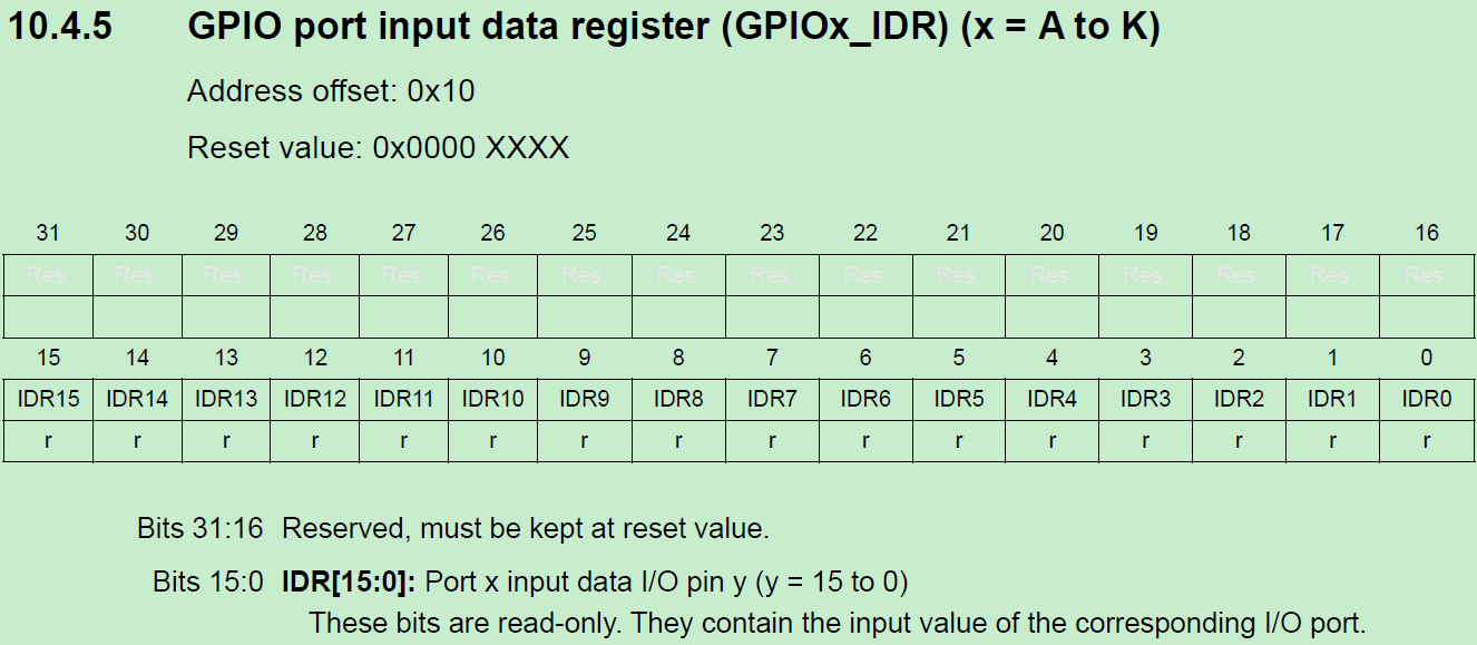
1.3.1 函数描述
此函数用于读取引脚状态,通过GPIO的IDR寄存器读取。
1.3.2 函数参数
◆ 第1个参数用于填写使用的端口号,从GPIOA到GPIOK。
◆ 第2个参数是配置选择的引脚,范围GPIO_PIN_0到GPIO_PIN_15。
1.4 函数 HAL_GPIO_WritePin()
/**
  * @brief  Sets or clears the selected data port bit.
  *
  * @note   This function uses GPIOx_BSRR register to allow atomic read/modify
  *         accesses. In this way, there is no risk of an IRQ occurring between
  *         the read and the modify access.
  *
  * @param  GPIOx: where x can be (A..K) to select the GPIO peripheral.
  * @param  GPIO_Pin: specifies the port bit to be written.
  *          This parameter can be one of GPIO_PIN_x where x can be (0..15).
  * @param  PinState: specifies the value to be written to the selected bit.
  *          This parameter can be one of the GPIO_PinState enum values:
  *            @arg GPIO_PIN_RESET: to clear the port pin
  *            @arg GPIO_PIN_SET: to set the port pin
  * @retval None
  */
void HAL_GPIO_WritePin(GPIO_TypeDef *GPIOx, uint16_t GPIO_Pin, GPIO_PinState PinState)
{
  /* Check the parameters */
  assert_param(IS_GPIO_PIN(GPIO_Pin));
  assert_param(IS_GPIO_PIN_ACTION(PinState));

  if (PinState != GPIO_PIN_RESET)
  {
    GPIOx->BSRR = GPIO_Pin;
  }
  else
  {
    GPIOx->BSRR = (uint32_t)GPIO_Pin << GPIO_NUMBER;
  }
}
1.4.1 函数描述
此函数用于设置引脚输出高电平或者低电平。使用GPIO的BSRR寄存器进行设置,使用这个寄存器的好处是支持原子操作,由硬件支持的。原子操作的含义是操作过程不会被中断打断,而我们使用GPIO中另一个设置输出的寄存ODR是会被中断打断的。大家看下寄存器赋值操作对应的反汇编,是由多条汇编指令组成的。
1.4.2 函数参数
◆ 第1个参数用于填写使用的端口号,从GPIOA到GPIAK。
◆ 第2个参数是配置选择的引脚,范围GPIO_PIN_0到GPIO_PIN_15。
◆ 第3个参数用于设置引脚输出高电平还是低电平,GPIO_PIN_RESET表示低电平,GPIO_PIN_SET表示高电平。
1.5 函数 HAL_GPIO_TogglePin()
/**
  * @brief  Toggles the specified GPIO pins.
  * @param  GPIOx: Where x can be (A..K) to select the GPIO peripheral.
  * @param  GPIO_Pin: Specifies the pins to be toggled.
  * @retval None
  */
void HAL_GPIO_TogglePin(GPIO_TypeDef *GPIOx, uint16_t GPIO_Pin)
{
  /* Check the parameters */
  assert_param(IS_GPIO_PIN(GPIO_Pin));

  if ((GPIOx->ODR & GPIO_Pin) == GPIO_Pin)
  {
    GPIOx->BSRR = (uint32_t)GPIO_Pin << GPIO_NUMBER;
  }
  else
  {
    GPIOx->BSRR = GPIO_Pin;
  }
}
1.5.1 函数描述
此函数用于设置引脚的电平翻转,使用GPIO的ODR寄存器进行设置。
1.5.2 函数参数
◆ 第1个参数用于填写使用的端口号,从GPIOA到GPIAK。
◆ 第2个参数是配置选择的引脚,范围GPIO_PIN_0到GPIO_PIN_15。
1.6 函数 HAL_GPIO_LockPin()
/**
  * @brief  Locks GPIO Pins configuration registers.
  * @note   The locked registers are GPIOx_MODER, GPIOx_OTYPER, GPIOx_OSPEEDR,
  *         GPIOx_PUPDR, GPIOx_AFRL and GPIOx_AFRH.
  * @note   The configuration of the locked GPIO pins can no longer be modified
  *         until the next reset.
  * @param  GPIOx: where x can be (A..K) to select the GPIO peripheral for STM32H7 family
  * @param  GPIO_Pin: specifies the port bit to be locked.
  *         This parameter can be any combination of GPIO_PIN_x where x can be (0..15).
  * @retval None
  */
HAL_StatusTypeDef HAL_GPIO_LockPin(GPIO_TypeDef *GPIOx, uint16_t GPIO_Pin)
{
  __IO uint32_t tmp = GPIO_LCKR_LCKK;

  /* Check the parameters */
  assert_param(IS_GPIO_LOCK_INSTANCE(GPIOx));
  assert_param(IS_GPIO_PIN(GPIO_Pin));

  /* Apply lock key write sequence */
  tmp |= GPIO_Pin;
  /* Set LCKx bit(s): LCKK='1' + LCK[15-0] */
  GPIOx->LCKR = tmp;
  /* Reset LCKx bit(s): LCKK='0' + LCK[15-0] */
  GPIOx->LCKR = GPIO_Pin;
  /* Set LCKx bit(s): LCKK='1' + LCK[15-0] */
  GPIOx->LCKR = tmp;
  /* Read LCKK register. This read is mandatory to complete key lock sequence*/
  tmp = GPIOx->LCKR;

  /* read again in order to confirm lock is active */
  if ((GPIOx->LCKR & GPIO_LCKR_LCKK) != 0x00U)
  {
    return HAL_OK;
  }
  else
  {
    return HAL_ERROR;
  }
}
1.6.1 函数描述
此函数用于锁住GPIO引脚所涉及到的寄存器,这些寄存器包括GPIOx_MODER,GPIOx_OTYPER,GPIOx_OSPEEDR,GPIOx_PUPDR,GPIOx_AFRL 和 GPIOx_AFRH。
1.6.2 函数参数
◆ 第1个参数用于填写使用的端口号,从GPIOA到GPIOK。
◆ 第2个参数是配置选择的引脚,范围GPIO_PIN_0到GPIO_PIN_15。
1.6.3 注意事项
- 此函数是锁住用户设置的引脚所对应的寄存器某些位,并不是把整个寄存器都锁住了。
- 一旦锁住后,就不能再修改,只有复位后才可以重新配置。
1.7 总结
◆ 第1步:使能GPIO所在总线的AHB时钟,__HAL_RCC_GPIOx_CLK_ENABLE()。
◆ 第2步:通过函数HAL_GPIO_Init()配置GPIO。
(1) 通过结构体GPIO_InitTypeDef的成员Mode配置输入、输出、模拟等模式。
(2) 通过结构体GPIO_InitTypeDef的成员Pull配置上拉、下拉电阻。
(3) 通过结构体GPIO_InitTypeDef的成员Speed配置GPIO速度等级。
(4) 如果选择了复用模式,那么就需要配置结构体GPIO_InitTypeDef的成员Alternate。
(5) 如果引脚功能用于ADC、DAC的话,需要配置引脚为模拟模式。
(6) 如果是用于外部中断/事件,结构体GPIO_InitTypeDef的成员Mode可以配置相应模式,相应的上 升沿、下降沿或者双沿触发也可以选择。
◆ 第3步:如果配置了外部中断/事件,可以通过函数HAL_NVIC_SetPriority设置优先级,然后调用函数 HAL_NVIC_EnableIRQ使能此中断。
◆ 第4步:输入模式读取引脚状态可以使用函数HAL_GPIO_ReadPin。
◆ 第5步:输出模式设置引脚状态可以调用函数HAL_GPIO_WritePin()和HAL_GPIO_TogglePin。
另外注意下面三个问题:
◆ 系统上电复位后,GPIO默认是模拟模式,除了JTAG相关引脚。
◆ 关闭LSE的话,用到的两个引脚OSC32_IN和OSC32_OUT(分别是PC14,PC15)可以用在通用IO,如 果开启了,就不能再做GPIO。
◆ 关闭HSE的话,用到的两个引脚OSC_IN和OSC_OUT(分别是PH0,PH1)可以用在通用IO,如果开启 了,就不能再做GPIO。
2、 stm32h7xx_ll_gpio.c
2.1 函数LL_GPIO_DeInit()
/**
* @brief De-initialize GPIO registers (Registers restored to their default values).
* @param GPIOx GPIO Port
* @retval An ErrorStatus enumeration value:
* - SUCCESS: GPIO registers are de-initialized
* - ERROR: Wrong GPIO Port
*/
ErrorStatus LL_GPIO_DeInit(GPIO_TypeDef *GPIOx)
{
ErrorStatus status = SUCCESS;
/* Check the parameters */
assert_param(IS_GPIO_ALL_INSTANCE(GPIOx));
/* Force and Release reset on clock of GPIOx Port */
if (GPIOx == GPIOA)
{
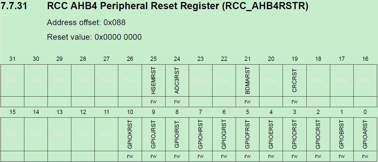
LL_AHB4_GRP1_ForceReset(LL_AHB4_GRP1_PERIPH_GPIOA);
/*
__STATIC_INLINE void LL_AHB4_GRP1_ForceReset(uint32_t Periphs)
{
SET_BIT(RCC->AHB4RSTR, Periphs);
}
#define SET_BIT(REG, BIT) ((REG) |= (BIT))
LL_AHB4_GRP1_PERIPH_GPIOA = 0x00000001
LL_AHB4_GRP1_ForceReset(LL_AHB4_GRP1_PERIPH_GPIOA)==>RCC->AHB4RSTR = 0x00000001
对应的就是GPIOARST置为1,对GPIOA进行复位,其他的引脚类似
*/
LL_AHB4_GRP1_ReleaseReset(LL_AHB4_GRP1_PERIPH_GPIOA);
/*
__STATIC_INLINE void LL_AHB4_GRP1_ReleaseReset(uint32_t Periphs)
{
CLEAR_BIT(RCC->AHB4RSTR, Periphs);
}
#define CLEAR_BIT(REG, BIT) ((REG) &= ~(BIT))
LL_AHB4_GRP1_PERIPH_GPIOA = 0x00000001
LL_AHB4_GRP1_ReleaseReset(LL_AHB4_GRP1_PERIPH_GPIOA)==>RCC->AHB4RSTR = 0x00000000
在进行复位之后再进行置0,保持默认状态,
*/
}
else if (GPIOx == GPIOB)
{
LL_AHB4_GRP1_ForceReset(LL_AHB4_GRP1_PERIPH_GPIOB);
LL_AHB4_GRP1_ReleaseReset(LL_AHB4_GRP1_PERIPH_GPIOB);
}
else if (GPIOx == GPIOC)
{
LL_AHB4_GRP1_ForceReset(LL_AHB4_GRP1_PERIPH_GPIOC);
LL_AHB4_GRP1_ReleaseReset(LL_AHB4_GRP1_PERIPH_GPIOC);
}
#if defined(GPIOD)
else if (GPIOx == GPIOD)
{
LL_AHB4_GRP1_ForceReset(LL_AHB4_GRP1_PERIPH_GPIOD);
LL_AHB4_GRP1_ReleaseReset(LL_AHB4_GRP1_PERIPH_GPIOD);
}
#endif /* GPIOD */
#if defined(GPIOE)
else if (GPIOx == GPIOE)
{
LL_AHB4_GRP1_ForceReset(LL_AHB4_GRP1_PERIPH_GPIOE);
LL_AHB4_GRP1_ReleaseReset(LL_AHB4_GRP1_PERIPH_GPIOE);
}
#endif /* GPIOE */
#if defined(GPIOF)
else if (GPIOx == GPIOF)
{
LL_AHB4_GRP1_ForceReset(LL_AHB4_GRP1_PERIPH_GPIOF);
LL_AHB4_GRP1_ReleaseReset(LL_AHB4_GRP1_PERIPH_GPIOF);
}
#endif /* GPIOF */
#if defined(GPIOG)
else if (GPIOx == GPIOG)
{
LL_AHB4_GRP1_ForceReset(LL_AHB4_GRP1_PERIPH_GPIOG);
LL_AHB4_GRP1_ReleaseReset(LL_AHB4_GRP1_PERIPH_GPIOG);
}
#endif /* GPIOG */
#if defined(GPIOH)
else if (GPIOx == GPIOH)
{
LL_AHB4_GRP1_ForceReset(LL_AHB4_GRP1_PERIPH_GPIOH);
LL_AHB4_GRP1_ReleaseReset(LL_AHB4_GRP1_PERIPH_GPIOH);
}
#endif /* GPIOH */
#if defined(GPIOI)
else if (GPIOx == GPIOI)
{
LL_AHB4_GRP1_ForceReset(LL_AHB4_GRP1_PERIPH_GPIOI);
LL_AHB4_GRP1_ReleaseReset(LL_AHB4_GRP1_PERIPH_GPIOI);
}
#endif /* GPIOI */
#if defined(GPIOJ)
else if (GPIOx == GPIOJ)
{
LL_AHB4_GRP1_ForceReset(LL_AHB4_GRP1_PERIPH_GPIOJ);
LL_AHB4_GRP1_ReleaseReset(LL_AHB4_GRP1_PERIPH_GPIOJ);
}
#endif /* GPIOJ */
#if defined(GPIOK)
else if (GPIOx == GPIOK)
{
LL_AHB4_GRP1_ForceReset(LL_AHB4_GRP1_PERIPH_GPIOK);
LL_AHB4_GRP1_ReleaseReset(LL_AHB4_GRP1_PERIPH_GPIOK);
}
#endif /* GPIOK */
else
{
status = ERROR;
}
return (status);
}

2.1.1 函数描述
此函数用于复位IO口到初始状态,将对应的GPIO口的所有引脚都复位成初始化的状态。
2.1.2 注意事项
初始化的时候,先进行复位,复位之后在进行设置成初始状态。
2.2 函数LL_GPIO_Init()
/**
  * @brief  Initialize GPIO registers according to the specified parameters in GPIO_InitStruct.
  * @param  GPIOx GPIO Port
  * @param GPIO_InitStruct pointer to a @ref LL_GPIO_InitTypeDef structure
  *         that contains the configuration information for the specified GPIO peripheral.
  * @retval An ErrorStatus enumeration value:
  *          - SUCCESS: GPIO registers are initialized according to GPIO_InitStruct content
  *          - ERROR:   Not applicable
  */
ErrorStatus LL_GPIO_Init(GPIO_TypeDef *GPIOx, LL_GPIO_InitTypeDef *GPIO_InitStruct)
{
  uint32_t pinpos, currentpin;

  /* Check the parameters */
  assert_param(IS_GPIO_ALL_INSTANCE(GPIOx));
  assert_param(IS_LL_GPIO_PIN(GPIO_InitStruct->Pin));
  assert_param(IS_LL_GPIO_MODE(GPIO_InitStruct->Mode));
  assert_param(IS_LL_GPIO_PULL(GPIO_InitStruct->Pull));

  /* ------------------------- Configure the port pins ---------------- */
  /* Initialize  pinpos on first pin set
    #define POSITION_VAL(VAL) (__CLZ(__RBIT(VAL)))
    在 STM32 中的作用是计算指定值 VAL 在二进制表示中最高位的位置。
    这里使用了一些内置的 CMSIS 函数,包括 __RBIT(反转位顺序)和 __CLZ(计算前导零位数)。
解释:
__RBIT(VAL):反转 VAL 的位顺序。例如,如果 VAL 的二进制表示为 1010,经过 __RBIT 操作后,变成 0101。
__CLZ(VAL):计算 VAL 的二进制表示中从左边开始的前导零位数。例如,如果 VAL 的二进制表示为 00001000,
那么 __CLZ 将返回 4,因为前面有 4 个 0。
因此,POSITION_VAL(VAL) 表达式通过先反转 VAL 的位顺序,然后计算前导零位数,最终得到了 VAL 在二进制表示中
最高位的位置(从右到左数)。这在某些应用中可以用于确定一个值的位宽度或者最高有效位的位置。
    */
  pinpos = POSITION_VAL(GPIO_InitStruct->Pin);


  /* Configure the port pins */
  while (((GPIO_InitStruct->Pin) >> pinpos) != 0x00000000U)
  {
    /* Get current io position */
    currentpin = (GPIO_InitStruct->Pin) & (0x00000001UL << pinpos);

    if (currentpin != 0x00000000U)
    {

      if ((GPIO_InitStruct->Mode == LL_GPIO_MODE_OUTPUT) || (GPIO_InitStruct->Mode == LL_GPIO_MODE_ALTERNATE))
      {
        /* Check Speed mode parameters */
        assert_param(IS_LL_GPIO_SPEED(GPIO_InitStruct->Speed));

        /* Speed mode configuration */
        LL_GPIO_SetPinSpeed(GPIOx, currentpin, GPIO_InitStruct->Speed);

        /* Check Output mode parameters */
        assert_param(IS_LL_GPIO_OUTPUT_TYPE(GPIO_InitStruct->OutputType));

        /* Output mode configuration*/
        LL_GPIO_SetPinOutputType(GPIOx, GPIO_InitStruct->Pin, GPIO_InitStruct->OutputType);

      }

      /* Pull-up Pull down resistor configuration*/
      LL_GPIO_SetPinPull(GPIOx, currentpin, GPIO_InitStruct->Pull);

      if (GPIO_InitStruct->Mode == LL_GPIO_MODE_ALTERNATE)
      {
        /* Check Alternate parameter */
        assert_param(IS_LL_GPIO_ALTERNATE(GPIO_InitStruct->Alternate));

        /* Alternate function configuration */
        if (currentpin < LL_GPIO_PIN_8)
        {
          LL_GPIO_SetAFPin_0_7(GPIOx, currentpin, GPIO_InitStruct->Alternate);
        }
        else
        {
          LL_GPIO_SetAFPin_8_15(GPIOx, currentpin, GPIO_InitStruct->Alternate);
        }
      }

      /* Pin Mode configuration */
      LL_GPIO_SetPinMode(GPIOx, currentpin, GPIO_InitStruct->Mode);
    }
    pinpos++;
  }

  return (SUCCESS);
}
3、总结
stm32h7xxx_xxx_gpio.c主要是进行GPIO的设置、复位、复用功能的设置。
xxx_init()函数对主要寄存器先进行检测状态,然后在进行位操作,先进性清零,再进行值设定,初始化某些寄存器。
同理xxx_deinit()函数,也是对寄存器操作,将寄存器恢复成初始状态。


 2250
2250

 被折叠的 条评论
为什么被折叠?
被折叠的 条评论
为什么被折叠?
 到【灌水乐园】发言


