


keke‘
想随手记录下在学习PS部分中断的过程,记录可以帮助我发现一些细节上面的问题,或许也会帮到你们。
在使用XIlinx开发软件SDK过程中,我参考了system.mss文件中的xgpiops_intr_example示例,通过调用相关函数,建立中断系统和中断服务函数。
在开发过程中,因为我是用的是zynq开发板,所以要常常翻阅UG585赛灵思官方提供的数据手册,手册中介绍了机制和原理,适合用到的时候去参考。
MIO 配置中断
首先打开xgpiops_intr_example示例,我们可以看到一下函数:
int GpioIntrExample(XScuGic *Intc, XGpioPs *Gpio, u16 DeviceId, u16 GpioIntrId)这个函数当中首先执行了对GPIO器件 ID 查找配置信息,然后初始化 Gpio driver,定义GPIO输入输出方向,使能要输出引脚,最后重点才是建立中断系统:
SetupInterruptSystem(Intc, Gpio, GPIO_INTERRUPT_ID);
转到该函数的定义,可以看到它和GPIO的初始化比较类似,也是先找到配置信息,初始化一些引脚,我们可以重点参考下面的代码来帮助我们移植。
	/*
	 * Connect the interrupt controller interrupt handler to the hardware
	 * interrupt handling logic in the processor.
	 */
	Xil_ExceptionRegisterHandler(XIL_EXCEPTION_ID_INT,
				(Xil_ExceptionHandler)XScuGic_InterruptHandler,
				GicInstancePtr);

	/*
	 * Connect the device driver handler that will be called when an
	 * interrupt for the device occurs, the handler defined above performs
	 * the specific interrupt processing for the device.
	 */
	Status = XScuGic_Connect(GicInstancePtr, GpioIntrId,
				(Xil_ExceptionHandler)XGpioPs_IntrHandler,
				(void *)Gpio);
	if (Status != XST_SUCCESS) {
		return Status;
	}
	/* Enable falling edge interrupts for all the pins in bank 0. */
	XGpioPs_SetIntrType(Gpio, GPIO_BANK, 0x00, 0xFFFFFFFF, 0x00);

	/* Set the handler for gpio interrupts. */
	XGpioPs_SetCallbackHandler(Gpio, (void *)Gpio, IntrHandler);


	/* Enable the GPIO interrupts of Bank 0. */
	XGpioPs_IntrEnable(Gpio, GPIO_BANK, (1 << Input_Pin));


	/* Enable the interrupt for the GPIO device. */
	XScuGic_Enable(GicInstancePtr, GpioIntrId);


	/* Enable interrupts in the Processor. */
	Xil_ExceptionEnableMask(XIL_EXCEPTION_IRQ);
上面这些代码的主要作用是设置并使能中断异常与中断处理函数,在移植代码的过程中,我们要重点关系参数的传递与相关具体函数的调用。
需要先明白,实例好以后是具有动态空间的。
整个函数的需要传入的第一个参数是一个实例化好的中断控制器,以指针形式传入,正如GPIO实例,我们要在主函数前先声明,记得包含xscugic.h的头文。第二个参数是实例化的GPIO,第三个参数是使能GPIO中断号,通过查阅手册我们知道GPIO中断号是52,找到GPIO_INTERRUPT_ID的定义,添加宏定义 #define GPIO_INTERRUPT_ID XPAR_XGPIOPS_0_INTR

接下来我们要做的事情,就是修改这些函数内部的参数。
    int setup_interrupt_system(XScuGic *gic_ins_ptr, XGpioPs *gpio, u16 GpioIntrId)
    {
            int status;
        XScuGic_Config *IntcConfig; //中断控制器配置信息

        //查找中断控制器配置信息并初始化中断控制器驱动
        IntcConfig = XScuGic_LookupConfig(INTC_DEVICE_ID);
        if (NULL == IntcConfig) {
        return XST_FAILURE;
        }

        status = XScuGic_CfgInitialize(gic_ins_ptr, IntcConfig,
        IntcConfig->CpuBaseAddress);
        if (status != XST_SUCCESS) {
        return XST_FAILURE;
        }

        //设置并使能中断异常
        Xil_ExceptionRegisterHandler(XIL_EXCEPTION_ID_INT,
        (Xil_ExceptionHandler) XScuGic_InterruptHandler, gic_ins_ptr);
        Xil_ExceptionEnable();

        //为中断设置中断处理函数
        status = XScuGic_Connect(gic_ins_ptr, GpioIntrId,
        (Xil_ExceptionHandler) intr_handler, (void *) gpio);
        if (status != XST_SUCCESS) {
        return status;
        }

        //使能来自于 Gpio 器件的中断
        XScuGic_Enable(gic_ins_ptr, GpioIntrId);

        //设置 KEY 按键的中断类型为下降沿中断
        XGpioPs_SetIntrTypePin(gpio, KEY, XGPIOPS_IRQ_TYPE_EDGE_FALLING);

        //使能按键 KEY 中断
        XGpioPs_IntrEnablePin(gpio, KEY);

        return XST_SUCCESS;
    }
写中断函数:
使用前先调用函数SetupInterruptSystem(Intc, Gpio, GPIO_INTERRUPT_ID)即可。
    static void intr_handler(void *callback_ref)
    {
        /**/

    }
使用AXI接口产生IRQ到GIC
IRQ是中断请求,GIC用于管理PL和PS的中断,把中断发送到CPU进行处理。
AXI接口可以调用AXI GPIO的IP核实现PL与PS数据快速交互,这里是从PL到PS。
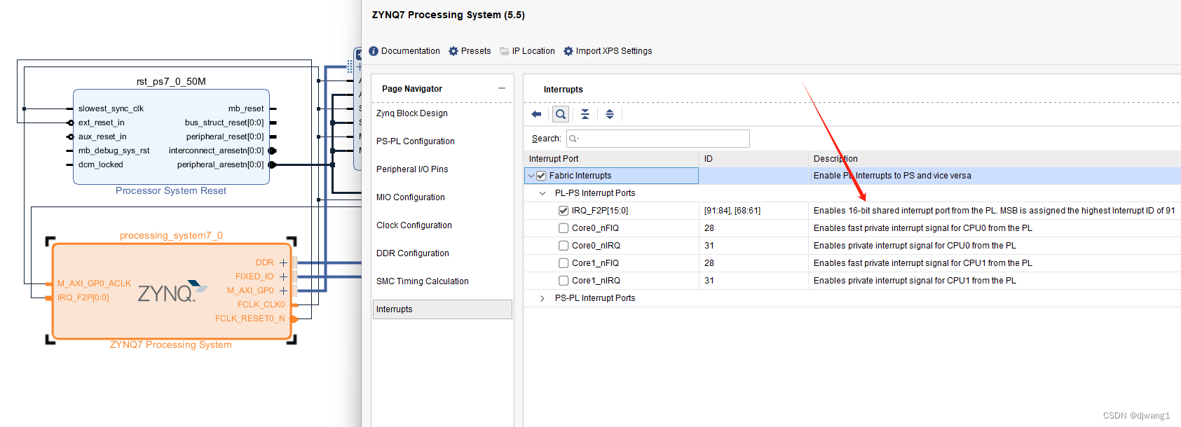
创建AXI GPIO IP核(互联作用),我们可以打开AMD—— AXI GPIO IP IP Product Guide
GPIOx_TRI register 使用三态缓冲区用于配置GPIO某一个引脚输入或是输出。
输出写0,输入写1。GPIO宽度可被配为1 - 32,其余较为常见,不做过多叙述。
PL端需要调用该IP核,与ZYNQ完成连接,做好管脚约束,(bit)直接导出HDL文件到SDK或Vitis即可。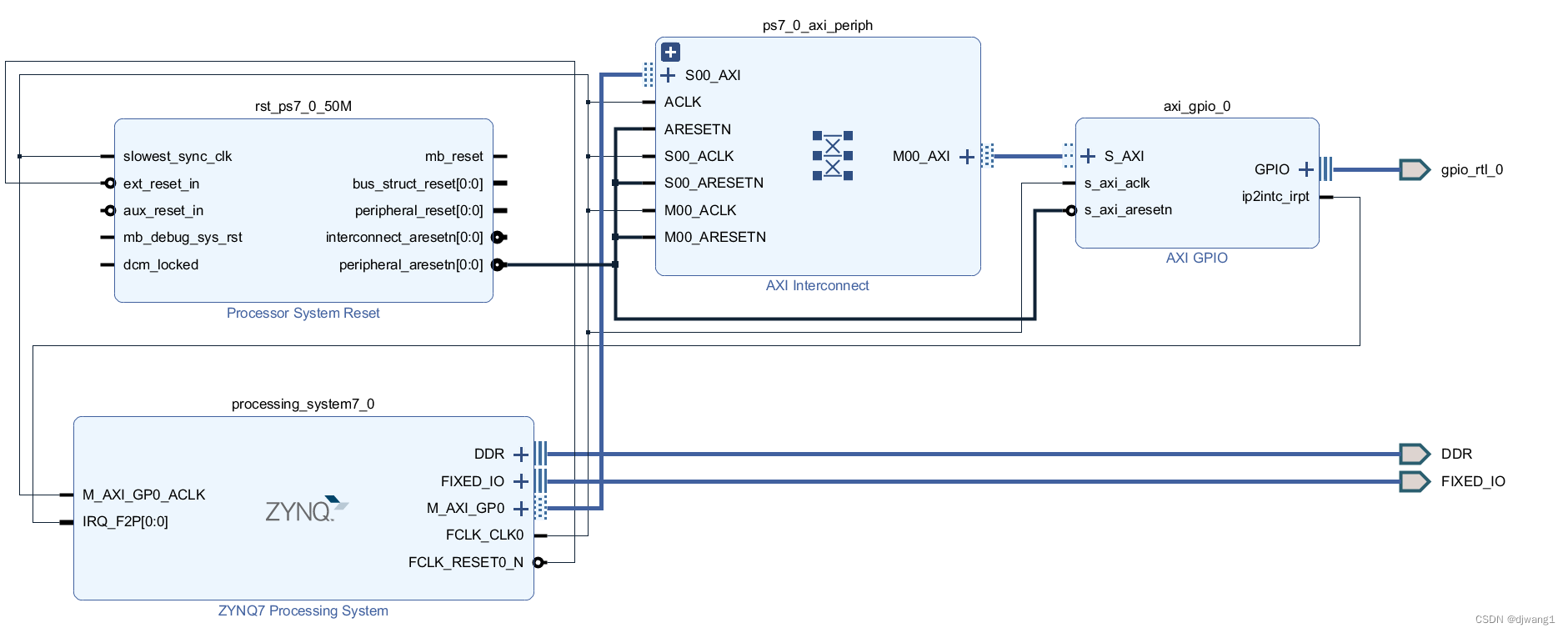
与PS端GPIO相同,我们也需要配置器件ID初始化AXI GPIO驱动,可通过调用以下函数直接完成。
XGpio_Initialize(&AXI_Gpio, AXI_GPIO_DEVICE_ID);可以在示例中找到AXI_GPIO的实例化函数和AXIGPIO的器件ID。
XGpio AXI_Gpio;  //实例化AXI
#define AXI_GPIO_DEVICE_ID		XPAR_GPIO_0_DEVICE_ID			//PL端 AXI GPIO器件ID
#define AXI_INTC_GPIO_INTERRUPT_ID	XPAR_INTC_0_GPIO_0_VEC_ID   //PL端 AXI GPIO中断ID
初始化好以后,我们可以查看pg144手册

首先设置AXIGPIO的方向,在xgpio.h文件中找到 :
void XGpio_SetDataDirection(XGpio *InstancePtr, unsigned Channel,
			    u32 DirectionMask);
第一个参数是实例化的AXIGPIO,传入其地址即;通道这里我们只用到一个通道,写1即可;最后一个输出方向,1为输出,0为输入。
其次打开全局中断和使能通道中断,为方便此步骤放在设置中断系统中。
查看示例,进行一步步移植:
int GpioSetupIntrSystem(INTC *IntcInstancePtr, XGpio *InstancePtr,
			u16 DeviceId, u16 IntrId, u16 IntrMask)
{
	int Result;

	GlobalIntrMask = IntrMask;

#ifdef XPAR_INTC_0_DEVICE_ID

#ifndef TESTAPP_GEN
	/*
	 * Initialize the interrupt controller driver so that it's ready to use.
	 * specify the device ID that was generated in xparameters.h
	 */
	Result = XIntc_Initialize(IntcInstancePtr, INTC_DEVICE_ID);
	if (Result != XST_SUCCESS) {
		return Result;
	}
#endif /* TESTAPP_GEN */

	/* Hook up interrupt service routine */
	XIntc_Connect(IntcInstancePtr, IntrId,
		      (Xil_ExceptionHandler)GpioHandler, InstancePtr);

	/* Enable the interrupt vector at the interrupt controller */
	XIntc_Enable(IntcInstancePtr, IntrId);

#ifndef TESTAPP_GEN
	/*
	 * Start the interrupt controller such that interrupts are recognized
	 * and handled by the processor
	 */
	Result = XIntc_Start(IntcInstancePtr, XIN_REAL_MODE);
	if (Result != XST_SUCCESS) {
		return Result;
	}
#endif /* TESTAPP_GEN */

#else /* !XPAR_INTC_0_DEVICE_ID */

#ifndef TESTAPP_GEN
	XScuGic_Config *IntcConfig;

	/*
	 * Initialize the interrupt controller driver so that it is ready to
	 * use.
	 */
	IntcConfig = XScuGic_LookupConfig(INTC_DEVICE_ID);
	if (NULL == IntcConfig) {
		return XST_FAILURE;
	}

	Result = XScuGic_CfgInitialize(IntcInstancePtr, IntcConfig,
					IntcConfig->CpuBaseAddress);
	if (Result != XST_SUCCESS) {
		return XST_FAILURE;
	}
#endif /* TESTAPP_GEN */

	XScuGic_SetPriorityTriggerType(IntcInstancePtr, IntrId,
					0xA0, 0x3);

	/*
	 * Connect the interrupt handler that will be called when an
	 * interrupt occurs for the device.
	 */
	Result = XScuGic_Connect(IntcInstancePtr, IntrId,
				 (Xil_ExceptionHandler)GpioHandler, InstancePtr);
	if (Result != XST_SUCCESS) {
		return Result;
	}

	/* Enable the interrupt for the GPIO device.*/
	XScuGic_Enable(IntcInstancePtr, IntrId);
#endif /* XPAR_INTC_0_DEVICE_ID */

	/*
	 * Enable the GPIO channel interrupts so that push button can be
	 * detected and enable interrupts for the GPIO device
	 */
	XGpio_InterruptEnable(InstancePtr, IntrMask);
	XGpio_InterruptGlobalEnable(InstancePtr);

	/*
	 * Initialize the exception table and register the interrupt
	 * controller handler with the exception table
	 */
	Xil_ExceptionInit();

	Xil_ExceptionRegisterHandler(XIL_EXCEPTION_ID_INT,
			 (Xil_ExceptionHandler)INTC_HANDLER, IntcInstancePtr);

	/* Enable non-critical exceptions */
	Xil_ExceptionEnable();

	return XST_SUCCESS;
}
可以看到示例函数中首先进行了条件编译,预处理指令,我们确定了选型,可以删除,接下来设置优先级:
void XScuGic_SetPriorityTriggerType(XScuGic *InstancePtr, u32 Int_Id,
					u8 Priority, u8 Trigger)
* @param InstancePtr is a pointer to the instance to be worked on.
* @param Int_Id is the IRQ source number to modify
* @param Priority is the new priority for the IRQ source. 0 is highest
* priority, 0xF8(248) is lowest. There are 32 priority levels
* supported with a step of 8. Hence the supported priorities are
* 0, 8, 16, 32, 40 ..., 248.
* @param Trigger is the new trigger type for the IRQ source.
对于最后一个参数:
* Each bit pair describes the configuration for an INT_ID.
* SFI Read Only b10 always
* PPI Read Only depending on how the PPIs are configured.
* b01 Active HIGH level sensitive
* b11 Rising edge sensitive
* SPI LSB is read only.
* b01 Active HIGH level sensitive
* b11 Rising edge sensitive/
我们只要重点关注中断源和想要触发的具体类型即可。
这里我们将其配置为上升沿触发:
XScuGic_SetPriorityTriggerType(&scugic_inst, GPIO_INT_ID, 0xA0, 0x3);接下来关联中断处理函数和其对应ID号,使能中断,注册中断异常函数即可:
    //关联中断 ID 和中断处理函数
    XScuGic_Connect(&scugic_inst, GPIO_INT_ID, axi_gpio_handler, &axi_gpio_inst);
    //使能 AXI GPIO 中断
    XScuGic_Enable(&scugic_inst, GPIO_INT_ID);

    //设置并打开中断异常处理功能
    Xil_ExceptionInit();
    Xil_ExceptionRegisterHandler(XIL_EXCEPTION_ID_INT,(Xil_ExceptionHandler)XScuGic_InterruptHandler, &scugic_inst);
    Xil_ExceptionEnable();
最后只要写好我们自己的中断服务函数就完成了配置,我们使用AXI接口的方式完成PL和PS的交互,在速率上要比EMIO更快速。


 1860
1860


 被折叠的 条评论
为什么被折叠?
被折叠的 条评论
为什么被折叠?
 到【灌水乐园】发言


