


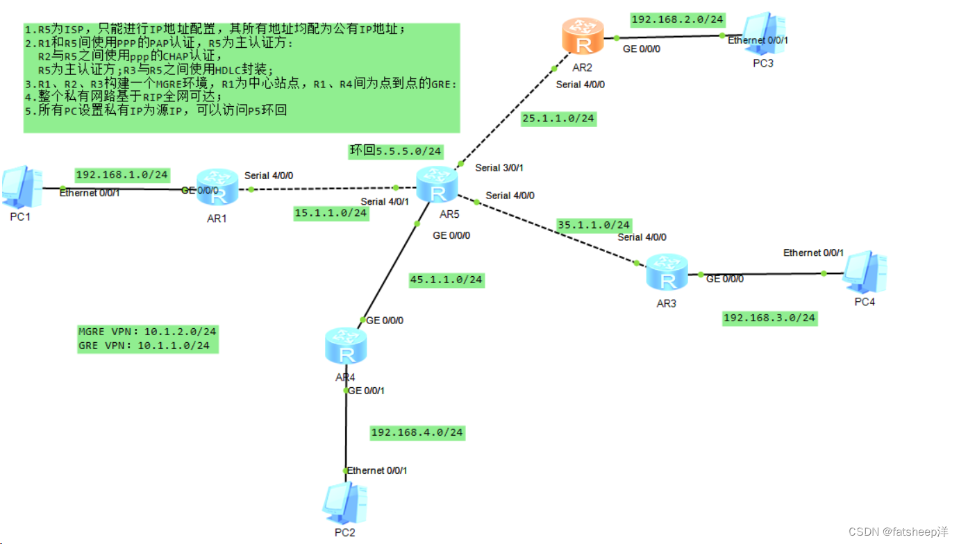
1、实验拓扑图:
2、实验要求
1.R5为ISP,只能进行IP地址配置,其所有地址均配为公有IP地址;
2.R1和R5间使用PPP的PAP认证,R5为主认证方:
R2与R5之间使用ppp的CHAP认证,
R5为主认证方;R3与R5之间使用HDLC封装;
3.R1、R2、R3构建一个MGRE环境,R1为中心站点,R1、R4间为点到点的GRE:
4.整个私有网路基于RIP全网可达;
5.所有PC设置私有IP为源IP,可以访问P5环回
3、实验思路
1.先给各个网段的设备配置IP地址
2.配置静态路由缺省,实现公网互通
3.使用ppp验证,R1与R5为PAP验证,R5为主认证方配置aaa地址池,创建用户名以及密码,同时进行pap服务认证,R1直连端口输入用户名,密码进行认证。
4.在R2、R5端口进行ppp的CHAP证思路跟3差不多
5.配置MGRE,GRE
6.配置RIP协议
7.配置NAT,使得访问内网环回
4、实验步骤
1.给各个设备配置IP
[R1-GigabitEthernet0/0/0]ip address 192.168.1.254 24
Mar 29 2024 17:50:56-08:00 R1 %%01IFNET/4/LINK_STATE(l)[0]:The line protocol IP
on the interface GigabitEthernet0/0/0 has entered the UP state.
[R1-GigabitEthernet0/0/0]Q
[R1]int s 4/0/0
[R1-Serial4/0/0]ip add 15.1.1.1 24
R2:
[R2]int g0/0/0
[R2-GigabitEthernet0/0/0]ip add 192.168.2.254 24
Mar 29 2024 17:56:17-08:00 R2 %%01IFNET/4/LINK_STATE(l)[0]:The line protocol IP
on the interface GigabitEthernet0/0/0 has entered the UP state.
[R2-GigabitEthernet0/0/0]q
[R2]int s 4/0/0
[R2-Serial4/0/0]ip add 25.1.1.2 24
[R2-Serial4/0/0]
R3:
[R3]int g 0/0/0
[R3-GigabitEthernet0/0/0]ip add 192.168.3.254 24
Mar 29 2024 17:58:01-08:00 R3 %%01IFNET/4/LINK_STATE(l)[0]:The line protocol IP
on the interface GigabitEthernet0/0/0 has entered the UP state.
[R3-GigabitEthernet0/0/0]q
[R3]int s 4/0/0
[R3-Serial4/0/0]ip add 35.1.1.3 24
[R3-Serial4/0/0]
R4:
[R4]int g 0/0/0
[R4-GigabitEthernet0/0/0]ip add 45.1.1.4 24
[R4-GigabitEthernet0/0/0]
Mar 29 2024 17:59:37-08:00 R4 %%01IFNET/4/LINK_STATE(l)[0]:The line protocol IP
on the interface GigabitEthernet0/0/0 has entered the UP state.
[R4-GigabitEthernet0/0/0]int g 0/0/1
[R4-GigabitEthernet0/0/1]ip add 192.168.4.254 24
Mar 29 2024 18:00:32-08:00 R4 %%01IFNET/4/LINK_STATE(l)[1]:The line protocol IP
on the interface GigabitEthernet0/0/1 has entered the UP state.
[R4-GigabitEthernet0/0/1]
R5:
[ISP]int g 0/0/0
[ISP-GigabitEthernet0/0/0]ip add 45.1.1.5 24
Mar 29 2024 18:02:14-08:00 ISP %%01IFNET/4/LINK_STATE(l)[0]:The line protocol IP
on the interface GigabitEthernet0/0/0 has entered the UP state.
[ISP-GigabitEthernet0/0/0]q
[ISP]int s 4/0/1
[ISP-Serial4/0/1]ip add 15.1.1.5 24
[ISP-Serial4/0/1]
Mar 29 2024 18:03:43-08:00 ISP %%01IFNET/4/LINK_STATE(l)[1]:The line protocol PP
P IPCP on the interface Serial4/0/1 has entered the UP state.
[ISP-Serial4/0/1]int s 3/0/1
[ISP-Serial3/0/1]ip add 25.1.1.5 24
[ISP-Serial3/0/1]
Mar 29 2024 18:07:05-08:00 ISP %%01IFNET/4/LINK_STATE(l)[2]:The line protocol PP
P IPCP on the interface Serial3/0/1 has entered the UP state.
[ISP-Serial3/0/1]int s 4/0/0
[ISP-Serial4/0/0]ip add 35.1.1.5 24
[ISP-Serial4/0/0]
Mar 29 2024 18:09:56-08:00 ISP %%01IFNET/4/LINK_STATE(l)[3]:The line protocol PP
P IPCP on the interface Serial4/0/0 has entered the UP state.
[ISP-Serial4/0/0]q
[ISP]int l0
[ISP-LoopBack0]ip add 5.5.5.5 24
[ISP-LoopBack0]q
2.给R1~4配置静态缺省,实现公网通
[R1]ip route-static 0.0.0.0 0 15.1.1.5
[R2]ip route-static 0.0.0.0 0 25.1.1.5
[R3]ip route-static 0.0.0.0 0 35.1.1.5
[R4]ip route-static 0.0.0.0 0 45.1.1.5
ping一下看是否实现了全网通

二、
R1和R5间使用PPP的PAP认证,R5为主认证方:
R5为主认证方
[ISP]aaa
[ISP-aaa]lo
[ISP-aaa]local-user wangdaye pa
[ISP-aaa]local-user wangdaye password ci
[ISP-aaa]local-user wangdaye password cipher wdy12345
Info: Add a new user.
[ISP-aaa]lo
[ISP-aaa]local-user wangdaye se
[ISP-aaa]local-user wangdaye service-type ppp
[ISP-aaa]q
R1:
[R1]int s 4/0/0
[R1-Serial4/0/0]ppp pap l
[R1-Serial4/0/0]ppp pap local-user wangdaye p
[R1-Serial4/0/0]ppp pap local-user wangdaye password ci
[R1-Serial4/0/0]ppp pap local-user wangdaye password cipher wdy12345
[R1-Serial4/0/0]
R2与R5之间使用ppp的CHAP认证,
R5
[ISP]aaa
[ISP-aaa]lo
[ISP-aaa]local-user zhangdaye pa
[ISP-aaa]local-user zhangdaye password ci
[ISP-aaa]local-user zhangdaye password cipher zdy12345
Info: Add a new user.
[ISP-aaa]q
[ISP]int Serial 3/0/1
[ISP-Serial3/0/1]ppp au
[ISP-Serial3/0/1]ppp authentication-mode chap
[ISP-Serial3/0/1]
[ISP-Serial3/0/1]
R2:
[R2]int s 4/0/0
[R2-Serial4/0/0]ppp chap u
[R2-Serial4/0/0]ppp chap user zhangdaye
[R2-Serial4/0/0]ppp chap p
[R2-Serial4/0/0]ppp chap password ci
[R2-Serial4/0/0]ppp chap password cipher zdy12345
[R2-Serial4/0/0]
R5为主认证方;R3与R5之间使用HDLC封装;
[ISP]int s 4/0/0
[ISP-Serial4/0/0]link-p
[ISP-Serial4/0/0]link-protocol h
[ISP-Serial4/0/0]link-protocol hdlc
Warning: The encapsulation protocol of the link will be changed. Continue? [Y/N]
:y
[R3]int s 4/0/0
[R3-Serial4/0/0]link
[R3-Serial4/0/0]link-protocol h
[R3-Serial4/0/0]link-protocol hdlc
Warning: The encapsulation protocol of the link will be changed. Continue? [Y/N]
:y
3.R1、R2、R3构建一个MGRE环境,R1为中心站点,R1、R4间为点到点的GRE:
MGRE:
[R1]int t
[R1]int Tunnel 0/0/1
[R1-Tunnel0/0/1]ip add 10.1.2.1 24
[R1-Tunnel0/0/1]tu
[R1-Tunnel0/0/1]tunnel-protocol gre p
[R1-Tunnel0/0/1]tunnel-protocol gre p2mp
[R1-Tunnel0/0/1]so
[R1-Tunnel0/0/1]source 15.1.1.1
Mar 29 2024 18:51:34-08:00 R1 %%01IFNET/4/LINK_STATE(l)[0]:The line protocol IP
on the interface Tunnel0/0/1 has entered the UP state.
[R2]int t
[R2]int Tunnel 0/0/1
[R2-Tunnel0/0/1]ip add 10.1.2.2 24
[R2-Tunnel0/0/1]tu
[R2-Tunnel0/0/1]tunnel-protocol gre p
[R2-Tunnel0/0/1]tunnel-protocol gre p2mp
[R2-Tunnel0/0/1]sou
[R2-Tunnel0/0/1]source 25.1.1.2
Mar 29 2024 18:54:30-08:00 R2 %%01IFNET/4/LINK_STATE(l)[0]:The line protocol IP
on the interface Tunnel0/0/1 has entered the UP state.
[R3]int t
[R3]int Tunnel 0/0/1
[R3-Tunnel0/0/1]ip add 10.1.2.3 24
[R3-Tunnel0/0/1]tu
[R3-Tunnel0/0/1]tunnel-protocol gre p
[R3-Tunnel0/0/1]tunnel-protocol gre p2mp
[R3-Tunnel0/0/1]so
[R3-Tunnel0/0/1]source 35.1.1.3
Mar 29 2024 18:55:34-08:00 R3 %%01IFNET/4/LINK_STATE(l)[0]:The line protocol IP
on the interface Tunnel0/0/1 has entered the UP state.
GRE:
[R1]INT t
[R1]INT Tunnel 0/0/0
[R1-Tunnel0/0/0]ip add 10.1.1.1 24
[R1-Tunnel0/0/0]tunnel-protocol gre
[R1-Tunnel0/0/0]so
[R1-Tunnel0/0/0]source 15.1.1.1
[R1-Tunnel0/0/0]de
[R1-Tunnel0/0/0]destination 45.1.1.4
Mar 29 2024 18:59:39-08:00 R1 %%01IFNET/4/LINK_STATE(l)[0]:The line protocol IP
on the interface Tunnel0/0/0 has entered the UP state.
[R4]int t
[R4]int Tunnel 0/0/0
[R4-Tunnel0/0/0]ip add 10.1.1.4 24
[R4-Tunnel0/0/0]tu
[R4-Tunnel0/0/0]tunnel-protocol gre
[R4-Tunnel0/0/0]so
[R4-Tunnel0/0/0]source 45.1.1.4
[R4-Tunnel0/0/0]de
[R4-Tunnel0/0/0]description
[R4-Tunnel0/0/0]destination 15.1.1.1
Mar 29 2024 19:03:29-08:00 R4 %%01IFNET/4/LINK_STATE(l)[0]:The line protocol IP
on the interface Tunnel0/0/0 has entered the UP state.
[R4-Tunnel0/0/0]
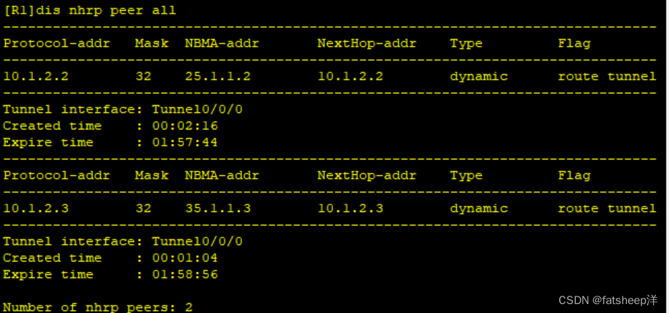
NHRP配置
中心站点R1:
[R1-Tunnel0/0/0]nhrp network-id 100
R2:
[R2-Tunnel0/0/0]nhrp network-id 100
[R2-Tunnel0/0/0]nhrp network-id 100try 10.1.2.1 15.1.1.1 register
R3:
[R3-Tunnel0/0/0]nhrp network-id 100
[R3-Tunnel0/0/0]nhrp entry 10.1.2.1 15.1.1.1 register
测试查看DHRP表
5.配置RIP
RIP使私网全网可达
RIP的宣告是按照主类宣告
R1:
[R1]rip 1
[R1-rip-1]undo su
| [R1-rip-1]undo summary(配RIP | 时,要消除自动汇总网段的功能) |
[R1-rip-1]v 2
[R1-rip-1]netw 192.168.1.0(宣告网段)
[R1-rip-1]netw 10.0.0.0
R2:
[R2]rip 1
[R2-rip-1]undo su
[R2-rip-1]undo summary
[R2-rip-1]v 2
[R2-rip-1]netw 192.168.2.0
[R2-rip-1]netw 10.0.0.0
R3:
[R3]rip 1
[[R3-rip-1]undo summary
[R3-rip-1]v 2
[R3-rip-1]netw 192.168.3.0
[R3-rip-1]netw 10.0.0.0
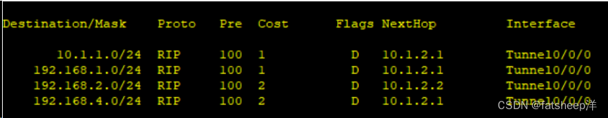
查看各rip路由学习情况


R2和R3没有学习到一条rip路由
解决方法:
在中心站点R1上开启伪广播,告诉分站点网段信息
[R1-Tunnel0/0/0]nhrp entry multicast dynamic

信息依旧不完整关闭RIP水平分割(rip协议自带防环机制,要关闭水平分割)
[R1-Tunnel0/0/0]undo rip split-horizon
[R2-Tunnel0/0/0]undo rip split-horizon
[R3-Tunnel0/0/0]undo rip split-horizon
[R4-Tunnel0/0/1]undo rip split-horizon
R3:
R2:

配置nat,使PC可以访问R5环回
[R1]acl 2000
[R1-acl-basic-2000]rule permit source 192.168.1.0 0.0.0.255
[R1-acl-basic-2000]int s4/0/0
[R1-Serial4/0/0]nat outbound 2000
[R2]acl 2000
[R2-acl-basic-2000]rule permit source 192.168.2.0 0.0.0.255
[R2-acl-basic-2000]int s 4/0/0
[R2-Serial4/0/0]nat outbound 2000
[R3]acl 2000
[R3-acl-basic-2000]rule permit source 192.168.3.0 0.0.0.255
[R3-acl-basic-2000]int s4/0/0
[R3-Serial4/0/0]nat outbound 2000
[R4]acl 2000
[R4-acl-basic-2000]rule permit source 192.168.4.0 0.0.0.255
[R4-acl-basic-2000]int g0/0/0
[R4-GigabitEthernet0/0/0]nat outbound 2000


 107
107


 被折叠的 条评论
为什么被折叠?
被折叠的 条评论
为什么被折叠?
 到【灌水乐园】发言


