


在软件行业,经常会听到一句话“文不如表,表不如图”说明了图形在软件应用中的重要性。同样在WPF开发中,为了程序美观或者业务需要,经常会用到各种个样的图形。今天以一些简单的小例子,简述WPF开发中几何图形(Geometry)相关内容,仅供学习分享使用,如有不足之处,还请指正。

什么是几何图形(Geometry)
几何图形可以随意和进行缩放而不变形,这是和位图最大的差异。Geometry类及其派生类(PathGeometry,EllipseGeometry,CombinedGeometry)可以用于描述2D形状的几何图形。Geometry对象可以是矩形和椭圆形等简单图形,也可以是由两个或者多个几何对象创建的复合图形,如:PathGeometry和StreamGeometry等,可以用于绘制曲线或其他复杂图形。Geometry类继承自Freezable类,因此可以声明为资源,对象之间共享,变为只读提高性能,或者克隆及线程安全等。具体可了解Freezable相关知识。
几何图形与形状的区别
上一篇文章了解了Shape类也是在页面绘制图形,那Shape和Geometry有什么区别和联系呢?
首先Geometry和Shape类都是用于描述2D形状(如:EllipseGeometry和Ellipse),但它们之间存在一些重要的区别。具体如下:
- Geometry继承自Freezable类,而Shape继承自FrameworkElement。所以Shape及其派生类可以在UI页面中独立存在并参与页面布局,而Geometry及其派生类则不能。
- 由于Shape类是UI无素,所以Shape类比Geometry更易于使用,但是Geometry却更通用,Shape用于呈现2D图形,但是Geometry可用于定义2D图形的几何区域,定义裁剪的区域或命中测试区域等。
- Shape派生类Path的Data属性,就是Geometry类型。所以可以理解为Shape是外在呈现形状,而Geometry是其内容,而Fill和Stroke属性,则对应画笔。
简单的几何图形
Geometry是abstract修饰的抽象类,所以只能使用其派生类进行绘制几何图形,而Geometry的派生类可以分为三个类别:简单几何,路径几何,复合几何。
简单几何图形,WPF系统自带了几个默认的几何图形,如LineGeometry,RectangleGeometry,和 EllipseGeometry,用于创建基本的几何图形,如:线条,矩形,椭圆等。
- LineGeometry,通过指定直线的起点和终点来定义线条。
- RectangleGeometry使有Rect结构来定义,指定矩形的相对位置,及高度和宽度。也可以使用RadiusX,RadiusY属性来创建圆角矩形。
- EllipseGeometry由中心点,x轴半径,y轴半径来创建椭圆,如果x轴半径和y轴半径相等,则为圆形。
虽然PathGeometry也能实现基本的几何图形,但是用WPF默认提供的类,则更简单,也方便理解。
LineGeometry
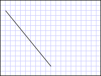
由于Geometry不是UI元素,不能独立进行自我绘制并呈现 ,所以使用Path形状来呈现。LineGeometry通过设置起始点坐标(StartPoint)和结束坐标(EndPoint)来定义直线。
如下所示:
<Path Stroke="Black" StrokeThickness="1" >
    <Path.Data>
        <LineGeometry StartPoint="10,20" EndPoint="100,130" />
    </Path.Data>
</Path>
上述代码通过C#代码实现,如下所示:
LineGeometry lineGeometry = new LineGeometry();
lineGeometry.StartPoint = new Point(10, 20);
lineGeometry.EndPoint = new Point(100, 130);

Path path = new Path();
path.Stroke = Brushes.Black;
path.StrokeThickness = 1;
path.Data = lineGeometry;
通过LineGeometry实现直线,效果如下所示:
EllipseGeometry
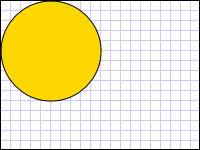
EllipseGeometry通过设置中心点的坐标(Center)和x半径(RadiusX),y轴半径(RadiusY)来绘制椭圆。
绘制一个坐标相等的圆,如下所示:
<Path Fill="Gold" Stroke="Black" StrokeThickness="1">
    <Path.Data>
        <EllipseGeometry Center="50,50" RadiusX="50" RadiusY="50" />
    </Path.Data>
</Path>
上述代码通过C#代码实现,如下所示:
EllipseGeometry ellipseGeometry = new EllipseGeometry();
ellipseGeometry.Center = new Point(50, 50);
ellipseGeometry.RadiusX = 50;
ellipseGeometry.RadiusY = 50;

Path path = new Path();
path.Fill = Brushes.Gold;
path.Stroke = Brushes.Black;
path.StrokeThickness = 1;
path.Data = ellipseGeometry;
通过EllipseGeometry绘制圆,示例如下所示:
RectangleGeometry
RectangleGeometry通会Rect结构来描述矩形,分别是起始坐标和宽度,高度来定义矩形,如下所示:
<Path Fill="LemonChiffon" Stroke="Black" StrokeThickness="1">
    <Path.Data>
        <RectangleGeometry Rect="50,50,100,60" />
    </Path.Data>
</Path>
上述代码用C#实现,如下所示:
RectangleGeometry rectangleGeometry = new RectangleGeometry();
rectangleGeometry.Rect = new Rect(50, 50, 100, 60);

Path path = new Path();
path.Fill = Brushes.LemonChiffon;
path.Stroke = Brushes.Black;
path.StrokeThickness = 1;
path.Data = rectangleGeometry;
通过RectangleGeometry绘制矩形,示例如下所示:

图像裁剪
通过将Geometry应用到Image的Clip属性,可以实现图像的裁剪功能,如下所示:
<StackPanel Orientation="Vertical" Margin="10">
    <TextBlock Text="原图"></TextBlock>
    <Image Source="imgs\bingdundun.jpeg" Width="300" Height="200" HorizontalAlignment="Left">
    </Image>
    <TextBlock Text="裁剪后"></TextBlock>
    <Image Source="imgs\bingdundun.jpeg" Width="300" Height="200" HorizontalAlignment="Left">
        <Image.Clip>
            <EllipseGeometry RadiusX="130" RadiusY="80" Center="150,100"/>
        </Image.Clip>
    </Image>
</StackPanel>
上述代码用C#实现如下所示:
Image image = new Image();
Uri imageUri = new Uri(@"imgs\bingdundun.jpeg", UriKind.RelativeOrAbsolute);
image.Source = new BitmapImage(imageUri);
image.Width = 300;
image.Height = 200;
image.HorizontalAlignment = HorizontalAlignment.Left;

// 用椭圆定义裁剪区域.
EllipseGeometry ellipseGeometry = new EllipseGeometry();
ellipseGeometry.Center = new Point(150, 10);
ellipseGeometry.RadiusX = 130;
ellipseGeometry.RadiusY = 80;
image.Clip = ellipseGeometry;
通过Geometry实现图像裁剪,示例如下所示:

路径几何
PathGeometry类及其轻型等效项(StreamGeometry类)主要用于描述弧线,曲线,直线组成的多个复杂图形的方法。PathGeometry的核心是PathFigure对你的集合。每一个PathFigure本身由一个或多个PathSegment对象组成,每一个PathSegment描述图形的一个小部分。常见的PathSegment主要有以下几种:
- ArcSegment,表示两点之间创建一条椭圆弧。
- BezierSegment,表示两个点之间的三次方贝塞尔曲线。
- LineSegment,表示两个点之间的直线。
- PolyBezierSegment,表示创建一系列的三次方贝塞尔曲线。
- PolyLineSegment,表示创建一系列直线。
- PolyQuadraticBezierSegment ,表示创建一系列二次贝塞尔曲线。
- QuadraticBezierSegment,表示创建一条贝塞尔曲线。
关于PathFigure有以下几点说明:
- PathFigure内的多个线段组合成单个几何形状,每个线段的终点,就是下一个线段的起点。
- PathFigure的StartPoint属性指定绘制第一个线段的起点。
- 每一个线段都从上一个线段的终点开始。
关于PathGeometry的示例代码如下所示:
<Path Stroke="Black" StrokeThickness="1" >
    <Path.Data>
        <PathGeometry>
            <PathGeometry.Figures>
                <PathFigure StartPoint="10,50">
                    <PathFigure.Segments>
                        <BezierSegment Point1="100,0" Point2="200,200" Point3="300,100"/>
                        <LineSegment Point="400,100" />
                        <ArcSegment Size="50,50" RotationAngle="45" IsLargeArc="True" SweepDirection="Clockwise" Point="200,100"/>
                    </PathFigure.Segments>
                </PathFigure>
            </PathGeometry.Figures>
        </PathGeometry>
    </Path.Data>
</Path>
上述XAML代码用C#实现,如下所示:
PathFigure pathFigure = new PathFigure();
pathFigure.StartPoint = new Point(10, 50);
pathFigure.Segments.Add(
    new BezierSegment(
        new Point(100, 0),
        new Point(200, 200),
        new Point(300, 100),
        true /* IsStroked */  ));
pathFigure.Segments.Add(
    new LineSegment(
        new Point(400, 100),
        true /* IsStroked */ ));
pathFigure.Segments.Add(
    new ArcSegment(
        new Point(200, 100),
        new Size(50, 50),
        45,
        true, /* IsLargeArc */
        SweepDirection.Clockwise,
        true /* IsStroked */ ));

/// Create a PathGeometry to contain the figure.
PathGeometry pathGeometry = new PathGeometry();
pathGeometry.Figures.Add(pathFigure);

// Display the PathGeometry.
Path path = new Path();
path.Stroke = Brushes.Black;
path.StrokeThickness = 1;
path.Data = pathGeometry;
上述代码创建的形状如下所示:

与 PathGeometry 类一样,StreamGeometry 定义可能包含曲线、弧线和直线的复杂几何形状。 与 PathGeometry 不同,StreamGeometry 的内容不支持数据绑定、动画或修改。 当需要描述复杂几何图形,但又不希望产生支持数据绑定、动画或修改的开销时,请使用 StreamGeometry。 由于 StreamGeometry 类的高效性,该类是描述装饰器的不错选择。
复合几何
使用 GeometryGroup、CombinedGeometry 或通过调用静态 Geometry 方法 Combine,可以创建复合几何对象。两者之间的差异如下:
- CombinedGeometry 对象和 Combine 方法执行布尔运算,以合并由两个几何图形定义的面积。 没有面积的 Geometry 对象将被放弃。 只能合并两个 Geometry 对象(尽管这两个几何图形也可能是复合几何)。
- GeometryGroup 类创建其包含的 Geometry 对象的合并,而不合并其面积。 可以将任意数量的 Geometry 对象添加到 GeometryGroup。由于它们不执行合并操作,因此使用 GeometryGroup 对象的性能比使用 CombinedGeometry 对象或 Combine 方法的性能高。
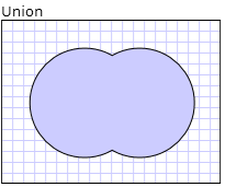
简单点来说:GeometryGroup是进行对象的合并,CombinedGeometry是进行合并对象的布尔运算。
下面示例CombinedGeometry的“并集”,如下所示:
<Path Stroke="Black" StrokeThickness="1" Fill="#CCCCFF">
    <Path.Data>
        <CombinedGeometry GeometryCombineMode="Union">
            <CombinedGeometry.Geometry1>
                <EllipseGeometry RadiusX="50" RadiusY="50" Center="75,75" />
            </CombinedGeometry.Geometry1>
            <CombinedGeometry.Geometry2>
                <EllipseGeometry RadiusX="50" RadiusY="50" Center="125,75" />
            </CombinedGeometry.Geometry2>
        </CombinedGeometry>
    </Path.Data>
</Path>
CombinedGeometry并集示例如下所示:
以上就是《不可不知的WPF几何图形(Geometry)》的全部内容,旨在抛砖引玉,一起学习,共同进步。


 1万+
1万+

 被折叠的 条评论
为什么被折叠?
被折叠的 条评论
为什么被折叠?
 到【灌水乐园】发言


