


 本文介绍了I/Q信号的概念,它们如何在射频系统中使用,并阐述了其优势。I/Q信号由同频且相位差90度的正弦和余弦波形组成,通常用于幅度调制而非频率或相位调制。通过调整I和Q信号的幅度,可以实现任意形式的调制,包括相位调制。I/Q调制在现代射频系统中的广泛应用,如四相相移键控(QPSK),可以通过分别对I和Q载波进行幅度调制并相加来实现不同相位的转换。
Learn about “I/Q” signals, how they are used, and why they are advantageous in RF systems.
This chapter would not be complete without a page on quadrature demodulation. However, before we explore quadrature demodulation, we need to at least briefly discuss quadrature modulation. And before we discuss quadrature modulation, we need to understand I/Q signals.
In-Phase and Quadrature
The term “I/Q” is an abbreviation for “in-phase” and “quadrature.” Unfortunately, we already have a terminology problem. First of all, “in-phase” and “quadrature” have no meaning on their own; phase is relative, and something can only be “in phase” or “out of phase” with reference to another signal or an established reference point. Furthermore, we now have the word “quadrature” applied to both a signal and the modulation/demodulation techniques associated with that signal.
In any event, “in-phase” and “quadrature” refer to two sinusoids that have the same frequency and are 90° out of phase. By convention, the I signal is a cosine waveform, and the Q signal is a sine waveform. As you know, a sine wave (without any additional phase) is shifted by 90° relative to a cosine wave. Another way to express this is that the sine and cosine waves are in quadrature.
The first thing to understand about I/Q signals is that they are always amplitude-modulated, not frequency- or phase-modulated. However, I/Q amplitude modulation is different from the AM technique discussed in Chapter 4: in an I/Q modulator, the signals that modulate the I/Q sinusoids are not shifted such that they are always positive. In other words, I/Q modulation involves multiplying I/Q waveforms by modulating signals that can have negative voltage values, and consequently the “amplitude” modulation can result in a 180° phase shift. Later in this page we’ll explore this issue in more detail.
What is so advantageous about amplitude-modulating two sinusoids that are 90° out of phase? Why are I/Q modulation and demodulation so widespread? Read on.
Summing I and Q
I and Q signals on their own are not very interesting. The interesting thing happens when I and Q waveforms are added. It turns out that any form of modulation can be performed simply by varying the amplitude—only the amplitude—of I and Q signals, and then adding them together.
If you take I and Q signals of equal amplitude and add them, the result is a sinusoid with a phase that is exactly between the phase of the I signal and the phase of the Q signal.
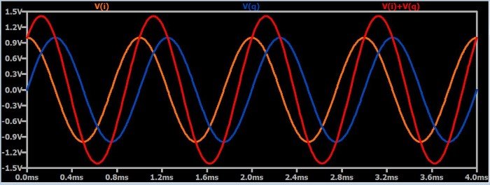
In other words, if you consider the I waveform to have a phase of 0° and the Q waveform to have a phase of 90°, the summation signal will have a phase of 45°. If you want to use these I and Q signals to create an amplitude-modulated waveform, you simply amplitude modulate the individual I and Q signals. Obviously a signal will increase or decrease in amplitude if it is created by adding together two signals that are both increasing or both decreasing in amplitude. However, you must ensure that the amplitude modulation applied to the I signal is identical to the amplitude modulation applied to the Q signal, because if they are not identical, you will have phase shift. And that brings us to the next property of I/Q signaling.
From Amplitude to Phase
Phase modulation, in the form of phase shift keying, is an important technique in modern RF systems, and phase modulation can be conveniently achieved by varying the amplitude of I/Q signals. Consider the following plots:
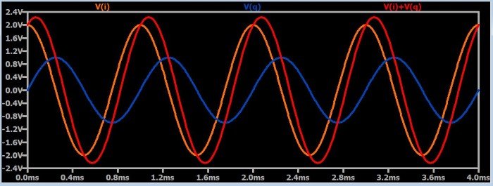
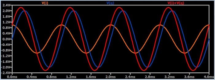
As you can see, increasing the amplitude of one of the waveforms relative to the other causes the summation signal to shift toward the higher-amplitude waveform. This makes intuitive sense: if you eliminated the Q waveform, for example, the summation would shift all the way over to the phase of the I waveform, because (obviously) adding the I waveform to zero will result in a summation signal that is identical to the I waveform.
It would seem from the above discussion that I/Q signaling can only be used to shift a signal 90° (i.e., 45° in each direction): if the Q amplitude is reduced to zero, the summation goes all the way to the I phase; if the I amplitude is reduced to zero, the summation goes all the way to the Q phase. How, then, could we use I/Q signals to create (for example) quadrature phase shift keying (QPSK), which uses phase values covering a range of 270°? We’ll discuss this in the next section.
Quadrature Modulation
The term “quadrature modulation” refers to modulation that is based on the summation of two signals that are in quadrature. In other words, it is I/Q-signal-based modulation. We’ll use QPSK as an example of how quadrature modulation works, and in the process we’ll see how amplitude modulation of I/Q signals can produce phase shifts beyond 90°.
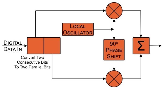
This is a basic block diagram for a QPSK modulator. First, the digital data stream is processed so that two consecutive bits become two parallel bits. Both of these bits will be transmitted simultaneously; in other words, as mentioned in this page, QPSK allows one symbol to transfer two bits. The local oscillator generates the carrier sinusoid. The local oscillator signal itself becomes the I carrier, and a 90° phase shift is applied to create the Q carrier. The I and Q carriers are multiplied by the I and Q data streams, and the two signals resulting from these multiplications are summed to produce the QPSK-modulated waveform.
The I and Q data streams are amplitude-modulating the I and Q carriers, and as explained above, these individual amplitude modulations can be used to produce phase modulation in the final signal. If the I and Q data streams were typical digital signals extending from ground to some positive voltage, we would be applying on-off keying to the I and Q carriers, and our phase shift would be restricted to 45° in either direction. However, if the I and Q data streams are bipolar signals—i.e., if they swing between a negative voltage and a positive voltage—our “amplitude modulation” is actually inverting the carrier whenever the input data is logic low (because the negative input voltage multiplied by the carrier results in inversion). This means that we will have four I/Q states:
- I normal and Q normal
- I normal and Q inverted
- I inverted and Q normal
- I inverted and Q inverted
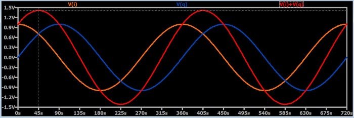
What will summation produce in each of these cases? (Note that in the following plots the frequency of the waveforms is chosen such that the number of seconds on the x-axis is the same as the phase shift in degrees.)
I Normal and Q Normal
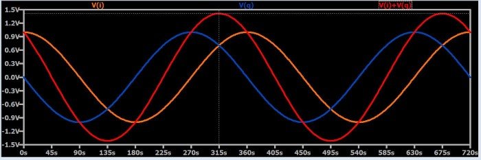
I Normal and Q Inverted
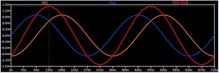
I Inverted and Q Normal
I Inverted and Q Inverted
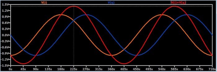
As you can see, summation in these four cases produces exactly what we want to have in a QPSK signal: phase shifts of 45°, 135°, 225°, and 315°.
Summary
- I/Q signaling refers to the use of two sinusoids that have the same frequency and a relative phase shift of 90°.
- Amplitude, phase, and frequency modulation can be performed by summing amplitude-modulated I/Q signals.
- Quadrature modulation refers to modulation that involves I/Q signals.
- Quadrature phase shift keying can be accomplished by adding I and Q carriers that have been individually multiplied, in accordance with the incoming digital data, by +1 or –1.


 被折叠的 条评论
为什么被折叠?
被折叠的 条评论
为什么被折叠?
 到【灌水乐园】发言


