


 本文主要介绍了网络链接层的功能和服务,包括帧定界、介质访问控制、可靠传输等。详细讨论了错误检测和纠正技术,如奇偶校验、校验和方法和循环冗余检查(CRC)。并探讨了在点对点和多路访问链接中如何协调帧传输。此外,还提到了在硬件和软件中实现链接层的重要性。
Please indicate the source: http://blog.csdn.net/gaoxiangnumber1
Welcome to my github: https://github.com/gaoxiangnumber1
- Two fundamentally different types of link-layer channels.
- Broadcast channels: connect multiple hosts in wireless LANs, satellite networks, and hybrid fiber-coaxial cable(HFC) access networks. Since many hosts are connected to the same broadcast communication channel, a medium access protocol is needed to coordinate frame transmission.
- Point-to-Point communication link: such as between two routers connected by a long-distance link.
5.1 Introduction to the Link Layer
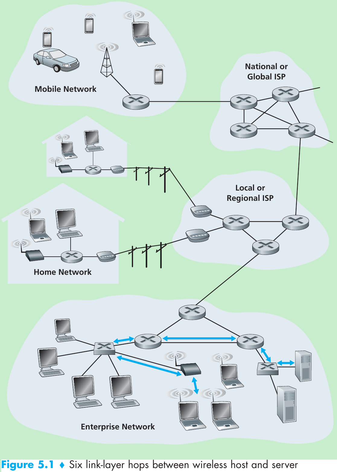
- Figure 5.1, consider sending a datagram from one of the wireless hosts to one of the servers. This datagram will pass through six links:
- a WiFi link between sending host and WiFi access point,
- an Ethernet link between the access point and a link-layer switch;
- a link between the link-layer switch and the router,
- a link between the two routers;
- an Ethernet link between the router and a link-layer switch;
- finally an Ethernet link between the switch and the server.
Over a given link, a transmitting node encapsulates the datagram in a link-layer frame and transmits the frame into the link.
5.1.1 The Services Provided by the Link Layer
- Framing. Almost all link-layer protocols encapsulate each network-layer datagram within a link-layer frame before transmission over the link. A frame consists of a data field, in which the network-layer datagram is inserted, and a number of header fields. The structure of the frame is specified by the link-layer protocol.
- Link access. A medium access control(MAC) protocol specifies the rules by which a frame is transmitted onto the link. For point-to-point links that have a single sender at one end of the link and a single receiver at the other end of the link, the MAC protocol is simple: the sender can send a frame whenever the link is idle. When multiple nodes share a single broadcast link(multiple access problem), the MAC protocol serves to coordinate the frame transmissions of the many nodes.
- Reliable delivery. This service guarantees to move each network-layer datagram across the link without error. It is often used for links that are prone to high error rates(wireless link…) with the goal of correcting an error locally(on the link where the error occurs) rather than forcing an end-to-end retransmission of the data by a transport- or application-layer protocol.
- Error detection and correction. This is done by having the transmitting node include error-detection bits in the frame, and having the receiving node perform an error check. Error correction is that a receiver detects determines where in the frame the errors have occurred and then corrects these errors.
5.1.2 Where Is the Link Layer Implemented?
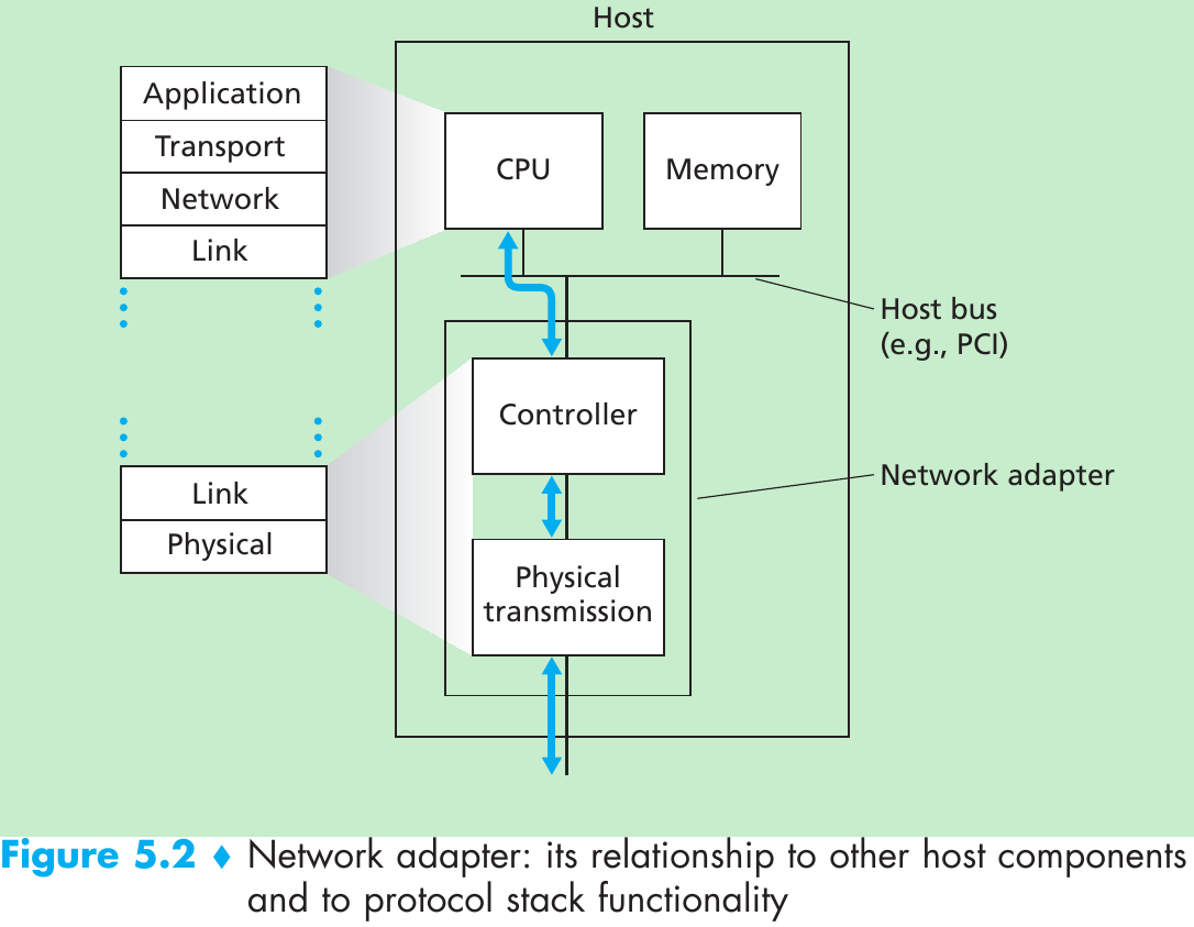
- Figure 5.2. The link layer is implemented in a network adapter(also known as network interface card(NIC)). At the heart of the network adapter is the link-layer controller, usually a single, special-purpose chip that implements many of the link-layer services. So, much of a link-layer controller’s functionality is implemented in hardware.
- On the sending side, the controller takes a datagram that has been created and stored in host memory by the higher layers of the protocol stack, encapsulates the datagram in a link-layer frame(filling in the frame’s various fields), and then transmits the frame into the communication link, following the link-access protocol.
- On the receiving side, a controller receives the entire frame, and extracts the network-layer datagram. If the link layer performs error detection, then it is the sending controller that sets the error-detection bits in the frame header and it is the receiving controller that performs error detection.
- Figure 5.2 shows that while most of the link layer is implemented in hardware, part of the link layer is implemented in software that runs on the host’s CPU. The software components of the link layer implement higher-level link-layer functionality such as assembling link-layer addressing information and activating the controller hardware. On the receiving side, link-layer software responds to controller interrupts(e.g., due to the receipt of one or more frames), handling error conditions and passing a datagram up to the network layer.
- Summary: the link layer is a combination of hardware and software.
5.2 Error-Detection and -Correction Techniques
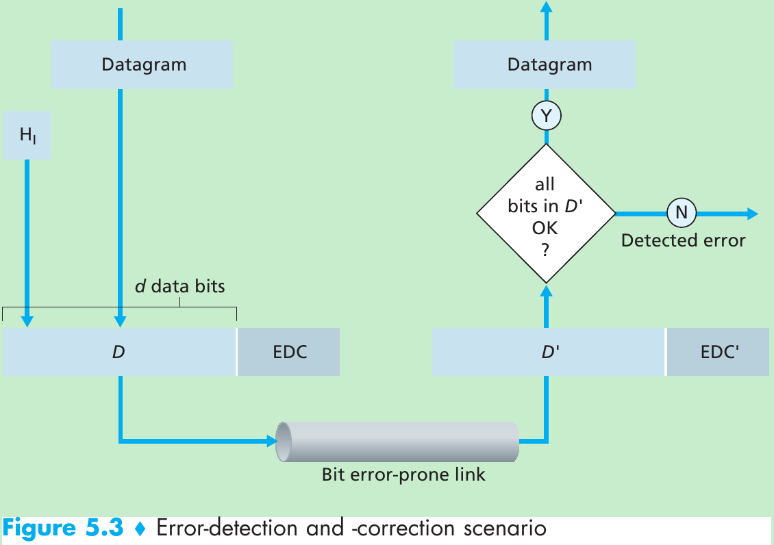
- Figure 5.3. At the sending node, data D to be protected against bit errors is augmented with error-detection and -correction bits(EDC). Both D and EDC are sent to the receiving node in a link-level frame. At the receiving node, a sequence of bits, D’ and EDC’ is received. The receiver’s challenge is to determine whether or not D’ is the same as the original D, given that it has only received D’ and EDC’.
- Error-detection and -correction techniques allow the receiver to detect that bit errors have occurred. But there still may be undetected bit errors.
- Let’s examine three techniques for detecting errors in the transmitted data: parity checks(illustrate the basic ideas behind error detection and correction), checksumming methods(typically used in the transport layer), and cyclic redundancy checks(typically used in the link layer in an adapter).
5.2.1 Parity Checks
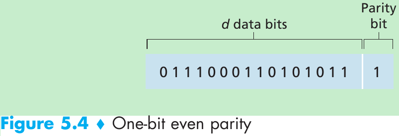
- Suppose that the information to be sent has d bits.
- For even parity scheme, the sender includes one additional bit and chooses its value such that the total number of 1s in the d + 1 bits(the original information plus a parity bit) is even.
- For odd parity scheme, the parity bit value is chosen such that there is an odd number of 1s.
- The receiver need count the number of 1s in the received d + 1 bits.
- If an odd number of 1-valued bits are found with an even parity scheme, the receiver knows that some odd number of bit errors have occurred.
- But even number of bit errors would result in an undetected error. Measurements have shown that errors are often clustered together in bursts. Under burst error conditions, the probability of undetected errors in a frame protected by single-bit parity can approach 50 percent.
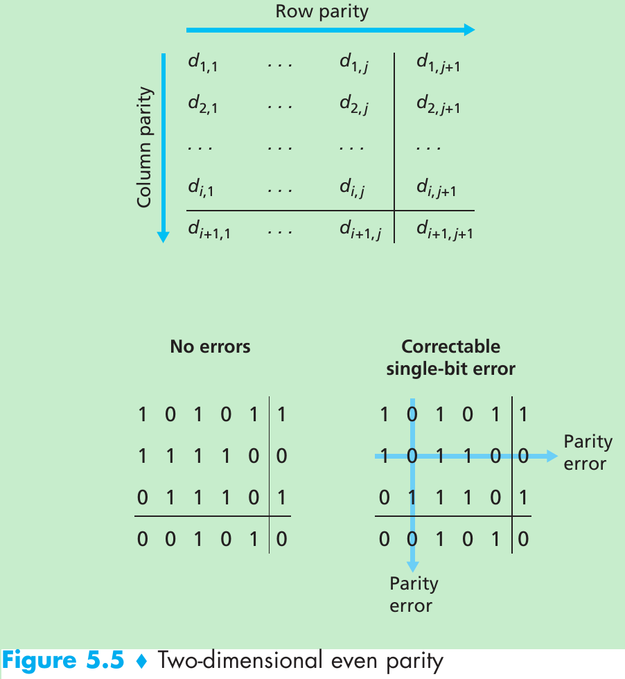
- Figure 5.5 shows a two-dimensional generalization of the single-bit parity scheme. The d bits in D are divided into i rows and j columns. A parity value is computed for each row and for each column. The resulting i + j + 1 parity bits comprise the link-layer frame’s error-detection bits.
- Suppose that a single bit error occurs in the original d bits of information. With this two-dimensional parity scheme, the parity of both the column and the row containing the flipped bit will be in error. The receiver can use the indices of the column and row with parity errors to identify the bit that was corrupted and correct that error. Two-dimensional parity can also detect but not correct any combination of two errors in a packet.
- The ability of the receiver to both detect and correct errors is known as forward error correction(FEC). FEC allows for immediate correction of errors at the receiver, thus decrease the number of sender retransmissions required.
5.2.2 Checksumming Methods
- The Internet checksum treats bytes of data as 16-bit integers and sum them. The 1s complement of this sum then forms the Internet checksum that is carried in the segment header. The receiver checks the checksum by taking the 1s complement of the sum of the received data(including the checksum) and checking whether the result is all 1 bits. If any of the bits are 0, an error is indicated.
- In TCP and UDP, the Internet checksum is computed over all fields(header and data fields included); in IP, the checksum is computed only over the IP header.
- Checksumming methods provide relatively weak protection against errors as compared with cyclic redundancy check. Why is checksumming used at the transport layer and cyclic redundancy check used at the link layer?
- Because transport-layer error detection is implemented in software, it is important to have a simple and fast error-detection scheme such as checksumming.
- Error detection at the link layer is implemented in dedicated hardware in adapters, which can rapidly perform the more complex CRC operations.
5.2.3 Cyclic Redundancy Check(CRC)
- CRC codes are also known as polynomial codes, since it is possible to view the bit string to be sent as a polynomial whose coefficients are the 0 and 1 values in the bit string, with operations on the bit string interpreted as polynomial arithmetic.
- Consider the d-bit piece of data, D, that the sending node wants to send. The sender and receiver must first agree on an r + 1 bit generator, G. We require that the leftmost bit of G be 1. Figure 5.6.
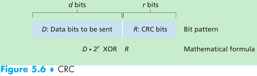
- For a given piece of data, D, the sender will choose r additional bits, R, and append them to D such that the resulting d + r bit pattern is exactly divisible by G(i.e., has no remainder) using modulo-2 arithmetic.
- The process of error checking with CRC: The receiver divides the d + r received bits by G. If the remainder is nonzero, an error has occurred; otherwise the data is accepted as being correct.
- All CRC calculations are done in modulo-2 arithmetic without carries in addition or borrows in subtraction. This means that addition and subtraction are identical, and both are equivalent to the bitwise exclusive-or(XOR) of the operands.
1011 - 0101 = 1011 XOR 0101 = 1110
1001 - 1101 = 1001 XOR 1101 = 0100 - Multiplication and division are the same as in base-2 arithmetic, except that any required addition or subtraction is done without carries or borrows. Given D and R, the quantity D * 2r XOR R yields the d + r bit pattern shown in Figure 5.6.
- We want to choose R such that G divides into D * 2r XOR R without remainder. If we XOR R to both sides of the above equation, we get D * 2r = nG XOR R.
This equation tells us that if we divide D * 2r by G, the value of the remainder is precisely R. So, we can calculate R as R = remainder(D * 2r / G).
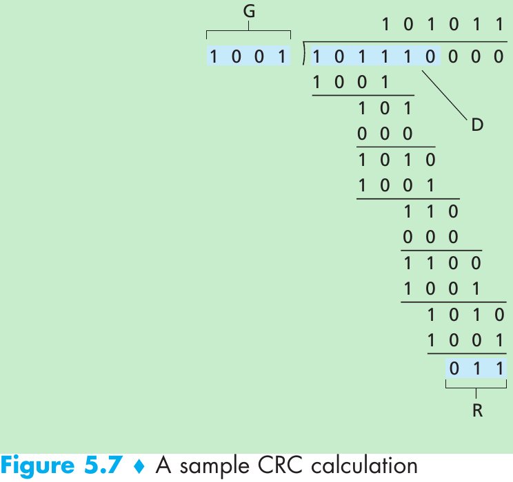
- Figure 5.7. D = 101110, d = 6, G = 1001, and r = 3. The 9 bits transmitted in this case are 101110 011.
- International standards have been defined for 8-, 12-, 16-, and 32-bit generators. The CRC-32 32-bit standard uses a generator of
GCRC-32 = 100000100110000010001110110110111 - Each of the CRC standards can detect burst errors of fewer than r + 1 bits. This means that all consecutive bit errors of r bits or fewer will be detected. Under appropriate assumptions, a burst of length greater than r + 1 bits is detected with probability 1 - 0.5r. Also, each of the CRC standards can detect any odd number of bit errors.
5.3 Multiple Access Links and Protocols
- Two types of network links: point-to-point links and broadcast links. Broadcast link can have multiple sending and receiving nodes all connected to the same, single, shared broadcast channel. Broadcast means when any one node transmits a frame, the channel broadcasts the frame and each of the other nodes receives a copy. Computer networks have multiple access protocols by which nodes regulate their transmission into the shared broadcast channel.
- Because all nodes are capable of transmitting frames, more than one node can transmit frames at the same time. When this happens, all of the nodes receive multiple frames at the same time. But none of the receiving nodes can make any sense of any of the frames that were transmitted. Thus, all the frames involved in the collision are lost, and the broadcast channel is wasted during the collision interval.
- The coordination for the transmissions of the active nodes is the responsibility of the multiple access protocol. Any multiple access protocol belongs to one of three categories: channel partitioning protocols, random access protocols, and taking turns protocols.
- Ideally, a multiple access protocol for a broadcast channel of rate R bits per second should have the following characteristics:
- When only one node has data to send, that node has a throughput of R bps.
- When M nodes have data to send, each of these nodes has a throughput of R/M bps. This need not necessarily imply that each of the M nodes always has an rate of R/M, but rather that each node should have an average transmission rate of R/M over defined interval of time.
- The protocol is decentralized: there is no master node that represents a single point of failure for the network.
- The protocol is simple, so that it is inexpensive to implement.
5.3.1 Channel Partitioning Protocols
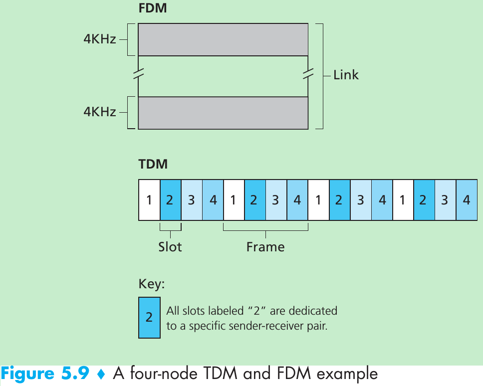
- Time-division multiplexing(TDM) and frequency-division multiplexing(FDM) are two techniques that can be used to partition a broadcast channel’s bandwidth among all nodes sharing that channel. Suppose the channel supports N nodes and the transmission rate of the channel is R bps.
- TDM divides time into time frames and divides each time frame into N time slots. Each time slot is then assigned to one of the N nodes. Whenever a node has a packet to send, it transmits the packet’s bits during its assigned time slot. Typically, slot sizes are chosen so that a single packet can be transmitted during a slot time. Figure 5.9 shows a four-node TDM example.
- Pros:
- Eliminates collisions.
- Fair: each node gets a transmission rate of R/N bps.
Cons: - A node is limited to an average rate of R/N bps even when it is the only node with packets to send.
- A node must wait for its turn in the transmission sequence even when it is the only node with frame to send.
- FDM divides the R bps channel into different frequencies(each with a bandwidth of R/N) and assigns each frequency to one of the N nodes. FDM creates N smaller channels of R/N bps out of the single, larger R bps channel. FDM shares both the advantages and drawbacks of TDM.
- A third channel partitioning protocol is code division multiple access(CDMA). CDMA assigns a different code to each node. Each node then uses its unique code to encode the data bits it sends. If the codes are chosen carefully, different nodes can transmit simultaneously and have their respective receivers correctly receive a sender’s encoded data bits in spite of interfering transmissions by other nodes.
5.3.2 Random Access Protocols
- In random access protocol:
- A transmitting node transmits at the full rate of the channel.
- When a node experiences a collision, it waits an independent random delay with other nodes before retransmitting the frame, therefore it is able to sneak its frame into the channel without a collision.
Slotted ALOHA
- Assume:
• All fra
 最低0.47元/天 解锁文章


 1796
1796

 被折叠的 条评论
为什么被折叠?
被折叠的 条评论
为什么被折叠?
 到【灌水乐园】发言


