


freeModbus包可进入后方链接下载(Modbus官方源码包)
MoubusRTU移植到stm32平台通信是通过串口进行通信,主要是需要串口进行收发,所以使用中断是必须的,在波特率设置问题上是和定时器相关联,在mbrtu.c文件的eMBRTUInit函数里具体说明了串口波特率和定时器设置的关系
eMBErrorCode
eMBRTUInit( UCHAR ucSlaveAddress, UCHAR ucPort, ULONG ulBaudRate, eMBParity eParity )
{
    eMBErrorCode    eStatus = MB_ENOERR;
    ULONG           usTimerT35_50us;

    ( void )ucSlaveAddress;
    ENTER_CRITICAL_SECTION(  );

    /* Modbus RTU uses 8 Databits. */
    if( xMBPortSerialInit( ucPort, ulBaudRate, 8, eParity ) != TRUE )
    {
        eStatus = MB_EPORTERR;
    }
    else
    {
        /* If baudrate > 19200 then we should use the fixed timer values
         * t35 = 1750us. Otherwise t35 must be 3.5 times the character time.
         */
        if( ulBaudRate > 19200 )
        {
            usTimerT35_50us = 35;       /* 1750us. */
        }
        else
        {
            /* The timer reload value for a character is given by:
             *
             * ChTimeValue = Ticks_per_1s / ( Baudrate / 11 )
             *             = 11 * Ticks_per_1s / Baudrate
             *             = 220000 / Baudrate
             * The reload for t3.5 is 1.5 times this value and similary
             * for t3.5.
             */
            usTimerT35_50us = ( 7UL * 220000UL ) / ( 2UL * ulBaudRate );
        }
        if( xMBPortTimersInit( ( USHORT ) usTimerT35_50us ) != TRUE )
        {
            eStatus = MB_EPORTERR;
        }
    }
    EXIT_CRITICAL_SECTION(  );

    return eStatus;
}
从上面代码的注释中可以看出,当波特率大于19200时,超时时间固定位为1750us,当波特率小于19200时,超时时间为3.5个字符时间,具体计算公式在代码注释里已经有了,程序波特率用115200,所以按照1750us来。
定时器设置
ModbusRTU是通过定时器和串口配合来实现Modbus通信的,所以定时器是决定有没有超时的一大关键问题,定时器设置是要配合串口设置的波特率,这里设置串口波特率为115200,然后就可以得到定时器设置,首先是设置APB1的主频率为240MHZ,modbus要求通过预分配后得到的周期为50us,对应频率为20KHz。根据rtu初始化代码设置自动重载值为35。
具体操作:
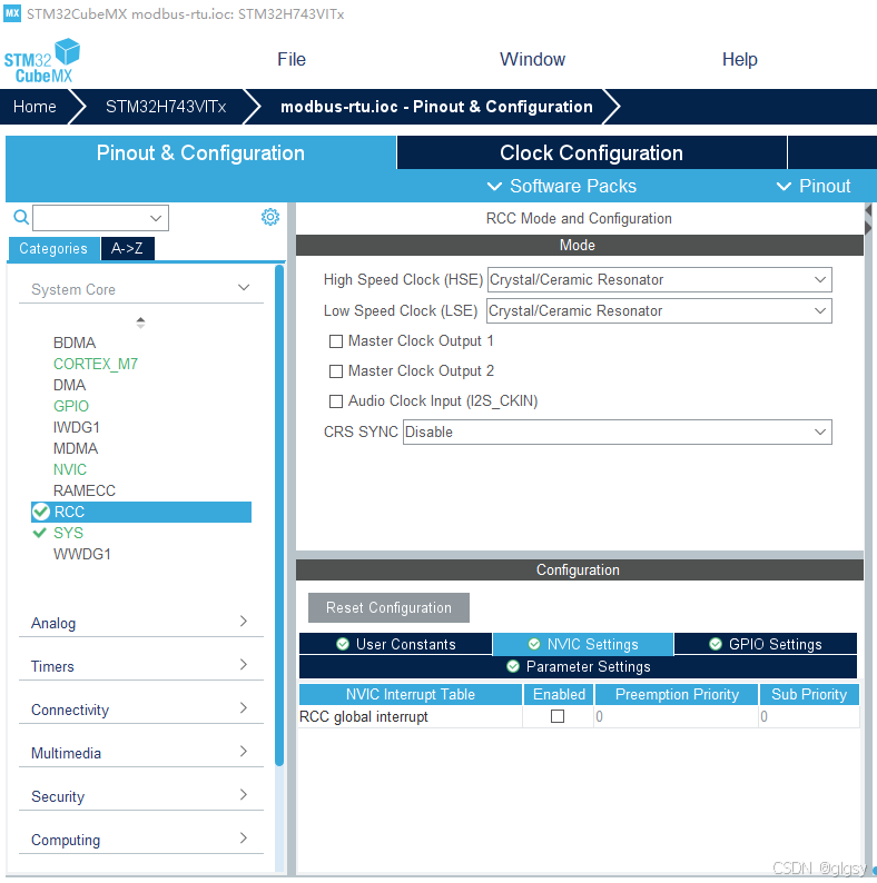
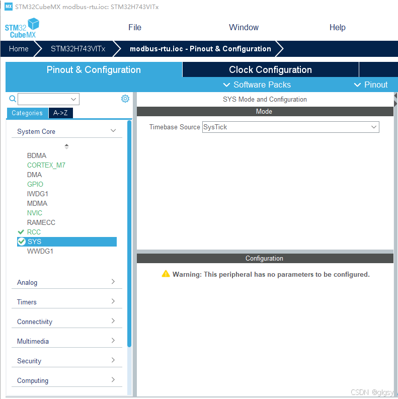
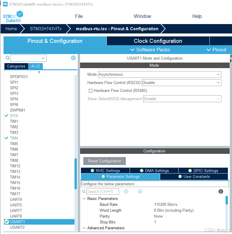
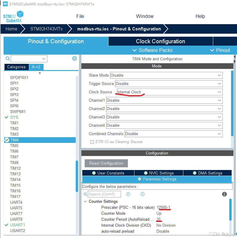
设置串口,选择异步通信,参数设置为115200,8,NONE,1
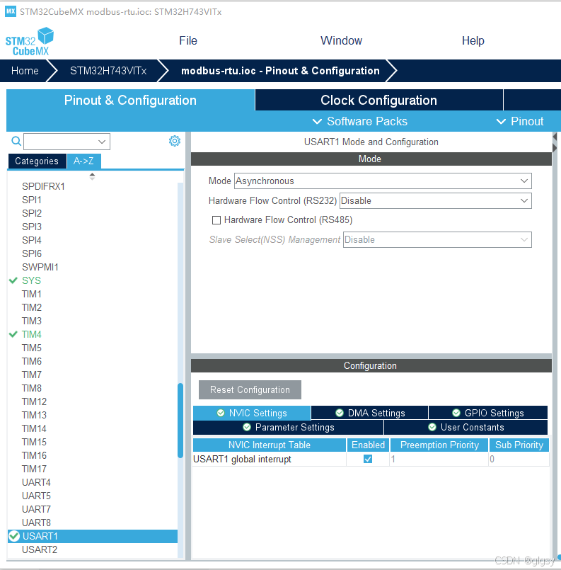
开启中断
设置主时钟频率为240MHZ,APB1的主频率为240MHZ。
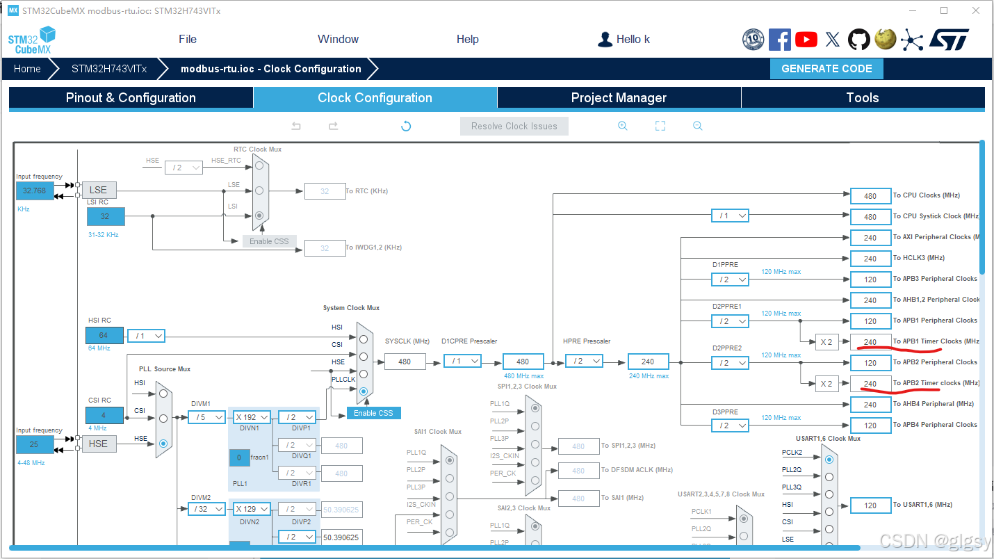
设置TIM4,使能定时器4,预分频系数为12000-1,对应的分频频率为20KHz,自动重载值设置为35,得到超时时间1750us。计算公式 T=(TIM_Period+1)*(TIM_Prescaler+1)/TIMxCLK,
12000*35/240=1750us。
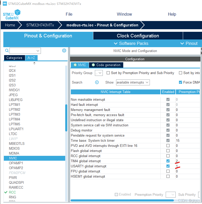
使能定时器中断
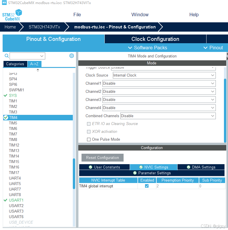
配置中断优先级,定时器中断优先级要低于串口中断
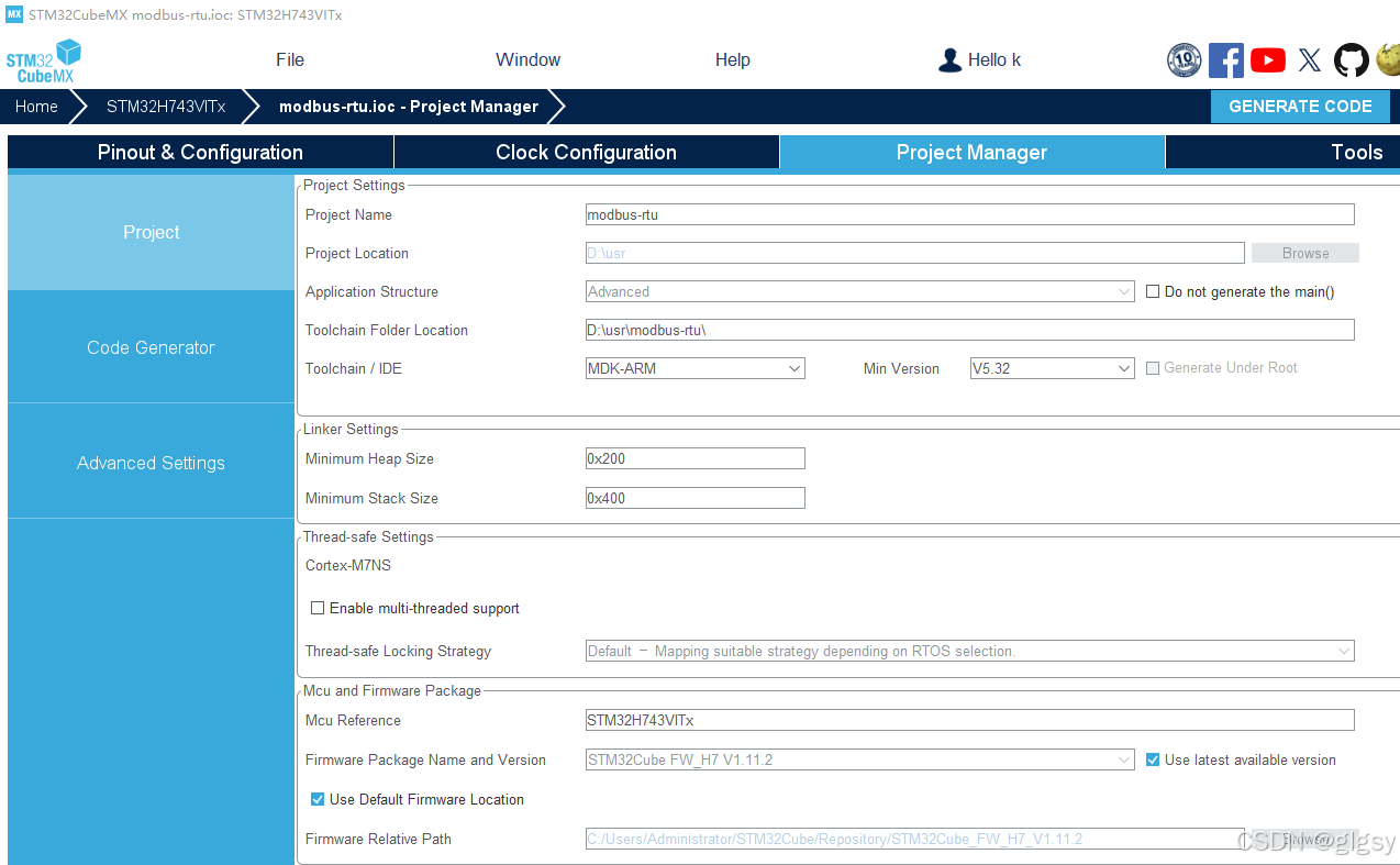
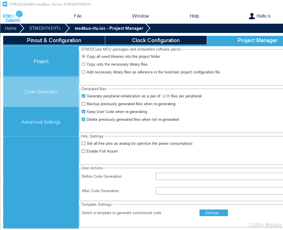
配置项目参数并分离头文件和c文件后生成代码
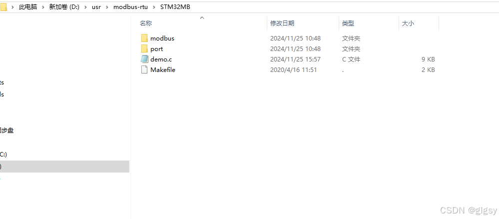
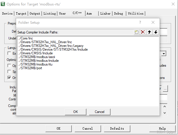
打开freeModbus代码包的demo文件夹,新建一个名为STM32MB的文件夹,之后将BARE文件夹内所有内容复制到STM32MB文件夹下。回到freeModbus代码包,复制整个modbus文件夹也粘贴到STM32MB文件夹内,完成效果如图
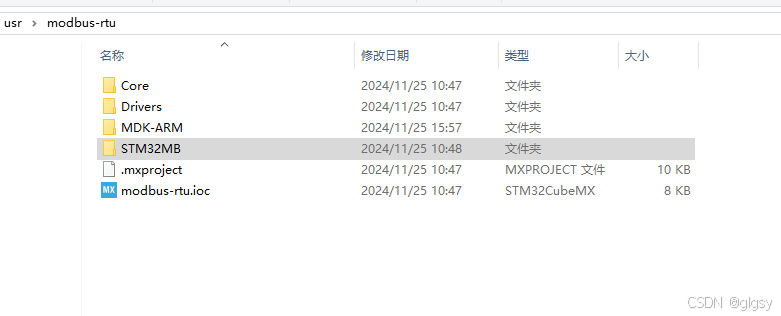
将STM32MB文件夹移动到stm32cubeMX生成的工程目录下
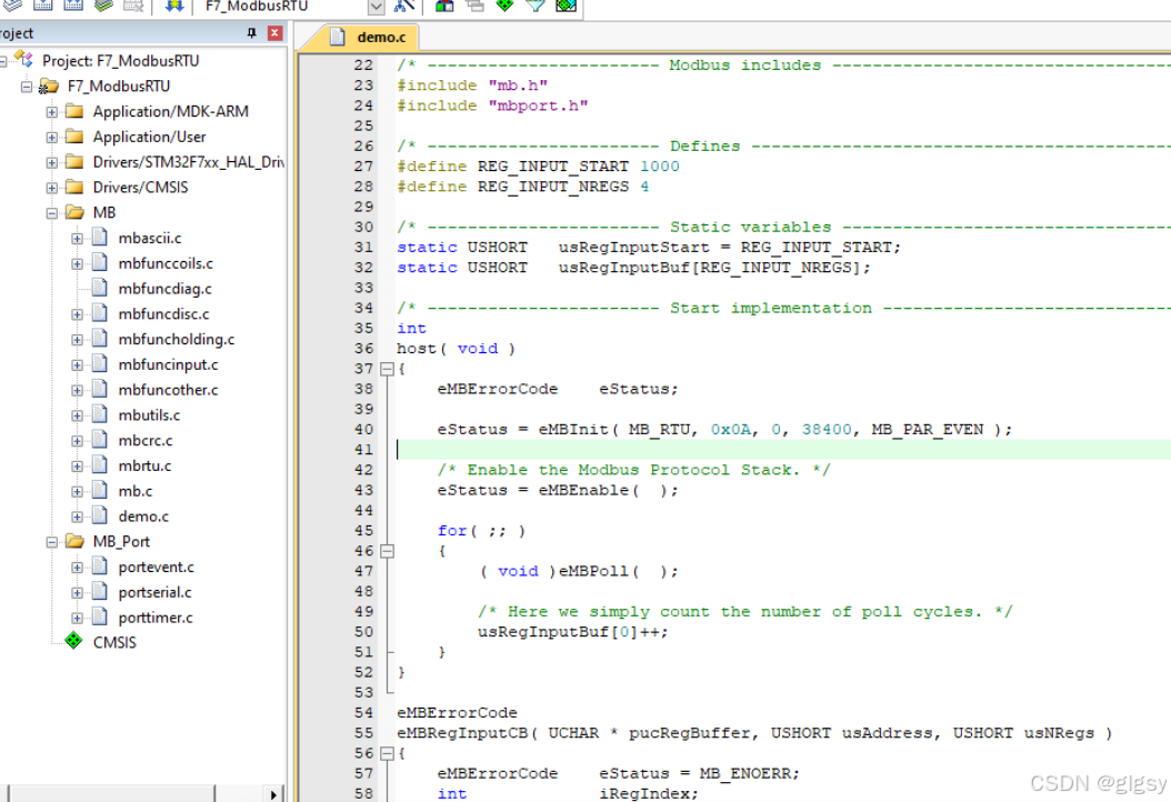
打开工程,引入STM32MB内的所有头文件,并新建名为MB和MB_Port的组,MB内添加STM32MB文件夹下modbus文件夹内所有c文件以及根目录的demo.c文件,MB_Port内添加STM32MB文件夹下port文件夹内所有c文件,如图所示
修改demo.c文件夹的main函数名为host,编译后不报错,才可以进行下一步。
修改MB_Port下的portserial.c文件(修改串口设置)
vMBPortSerialEnable()   //封装了接口(串口)的发送与接收使能\失能
xMBPortSerialInit()     //接口(串口)的初始化
xMBPortSerialPutByte()  //接口(串口)的发送函数
xMBPortSerialGetByte()  //接口(串口)的接收函数
USART1_IRQHandler()     //串口中断触发上面的接收与发送回调函数
#include "port.h"
#include "stm32h7xx_hal.h"
#include "usart.h"
/* ----------------------- Modbus includes ----------------------------------*/
#include "mb.h"
#include "mbport.h"
/* ----------------------- static functions ---------------------------------*/
//static void prvvUARTTxReadyISR( void );
//static void prvvUARTRxISR( void );
/* ----------------------- Start implementation -----------------------------*/
void
vMBPortSerialEnable( BOOL xRxEnable, BOOL xTxEnable )
{
/* If xRXEnable enable serial receive interrupts. If xTxENable enable
* transmitter empty interrupts.
*/
if (xRxEnable) //将串口收发中断和modbus联系起来,下面的串口改为自己使能的串口
{
__HAL_UART_ENABLE_IT(&huart1,UART_IT_RXNE); //我用的是串口2,故为&huart1
}
else
{
__HAL_UART_DISABLE_IT(&huart1,UART_IT_RXNE);
}
if (xTxEnable)
{
__HAL_UART_ENABLE_IT(&huart1,UART_IT_TXE);
}
else
{
__HAL_UART_DISABLE_IT(&huart1,UART_IT_TXE);
}
}
BOOL
xMBPortSerialInit( UCHAR ucPORT, ULONG ulBaudRate, UCHAR ucDataBits, eMBParity eParity )
{
return TRUE; //改为TURE,串口初始化在usart.c定义,mian函数已完成
}
BOOL
xMBPortSerialPutByte( CHAR ucByte )
{
/* Put a byte in the UARTs transmit buffer. This function is called
* by the protocol stack if pxMBFrameCBTransmitterEmpty( ) has been
* called. */
if(HAL_UART_Transmit (&huart1 ,(uint8_t *)&ucByte,1,0x01) != HAL_OK ) //添加发送一位代码
return FALSE ;
else
return TRUE;
}
BOOL
xMBPortSerialGetByte( CHAR * pucByte )
{
/* Return the byte in the UARTs receive buffer. This function is called
* by the protocol stack after pxMBFrameCBByteReceived( ) has been called.
*/
if(HAL_UART_Receive (&huart1 ,(uint8_t *)pucByte,1,0x01) != HAL_OK )//添加接收一位代码
return FALSE ;
else
return TRUE;
}
/* Create an interrupt handler for the transmit buffer empty interrupt
* (or an equivalent) for your target processor. This function should then
* call pxMBFrameCBTransmitterEmpty( ) which tells the protocol stack that
* a new character can be sent. The protocol stack will then call
* xMBPortSerialPutByte( ) to send the character.
*/
//static
void prvvUARTTxReadyISR( void ) //删去前面的static,方便在串口中断使用
{
pxMBFrameCBTransmitterEmpty( );
}
/* Create an interrupt handler for the receive interrupt for your target
* processor. This function should then call pxMBFrameCBByteReceived( ). The
* protocol stack will then call xMBPortSerialGetByte( ) to retrieve the
* character.
*/
//static
void prvvUARTRxISR( void ) //删去前面的static,方便在串口中断使用
{
pxMBFrameCBByteReceived( );
}
修改MB_Port下的porttimer.c文件(修改定时器设置)
/* ----------------------- Platform includes --------------------------------*/
#include "port.h"
#include "stm32h7xx_hal.h"
#include "tim.h"
/* ----------------------- Modbus includes ----------------------------------*/
#include "mb.h"
#include "mbport.h"

/* ----------------------- static functions ---------------------------------*/
//static void prvvTIMERExpiredISR( void );

/* ----------------------- Start implementation -----------------------------*/
BOOL
xMBPortTimersInit( USHORT usTim1Timerout50us )		//定时器初始化直接返回TRUE,已经在mian函数初始化过
{
    return TRUE;
}


inline void
vMBPortTimersEnable(  )		//使能定时器中断,我用的是定时器4,所以为&htim4
{
    /* Enable the timer with the timeout passed to xMBPortTimersInit( ) */
		__HAL_TIM_CLEAR_IT(&htim4,TIM_IT_UPDATE);
		__HAL_TIM_ENABLE_IT(&htim4,TIM_IT_UPDATE);
		__HAL_TIM_SetCounter(&htim4,0);
		__HAL_TIM_ENABLE(&htim4);
}

inline void
vMBPortTimersDisable(  )	//取消定时器中断
{
    /* Disable any pending timers. */
			__HAL_TIM_DISABLE(&htim4);
			__HAL_TIM_SetCounter(&htim4,0);
			__HAL_TIM_DISABLE_IT(&htim4,TIM_IT_UPDATE);
			__HAL_TIM_CLEAR_IT(&htim4,TIM_IT_UPDATE);
}

/* Create an ISR which is called whenever the timer has expired. This function
 * must then call pxMBPortCBTimerExpired( ) to notify the protocol stack that
 * the timer has expired.
 */
//static
void prvvTIMERExpiredISR( void )	//modbus定时器动作,需要在中断内使用
{
    ( void )pxMBPortCBTimerExpired(  );
}
修改完Modbus与stm32的接口文件之后要在port.h文件内定义总中断
修改为如下所示,并在port.h前包含上stm32的hal库 #include "stm32h7xx_hal.h",如图所示
#define ENTER_CRITICAL_SECTION( )   __set_PRIMASK(1) 	 //关总中断
#define EXIT_CRITICAL_SECTION( )    __set_PRIMASK(0)   //开总中断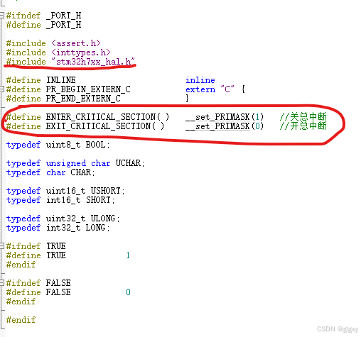
modbus端口函数到此修改完成,接下来是中断函数
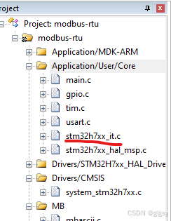
stm32h7xx_it.c中串口及定时器中断修改
打开工程内的中断文件,是在Application/User–>stm32h7xx_it.c
中添加以下代码,用于和modbus的串口和定时器功能代码联系
void USART1_IRQHandler(void)
{
  /* USER CODE BEGIN USART1_IRQn 0 */

  /* USER CODE END USART1_IRQn 0 */
  HAL_UART_IRQHandler(&huart1);
  /* USER CODE BEGIN USART1_IRQn 1 */
if(__HAL_UART_GET_IT_SOURCE(&huart1, UART_IT_RXNE)!= RESET)
		{
			prvvUARTRxISR();//接收中断
		}

	if(__HAL_UART_GET_IT_SOURCE(&huart1, UART_IT_TXE)!= RESET)
		{
			prvvUARTTxReadyISR();//发送中断
		}

  HAL_NVIC_ClearPendingIRQ(USART1_IRQn);
  HAL_UART_IRQHandler(&huart1);
  /* USER CODE END USART1_IRQn 1 */
}
在Application/User–>stm32h7xx_it.c末尾的/* USER CODE BEGIN 1 */添加定时器中断回调函数如下:
/* USER CODE BEGIN 1 */
void HAL_TIM_PeriodElapsedCallback(TIM_HandleTypeDef *htim)	//定时器中断回调函数,用于连接porttimer.c文件的函数
{
  /* NOTE : This function Should not be modified, when the callback is needed,
            the __HAL_TIM_PeriodElapsedCallback could be implemented in the user file
   */
  	prvvTIMERExpiredISR( );
}
/* USER CODE END 1 */
modbus功能
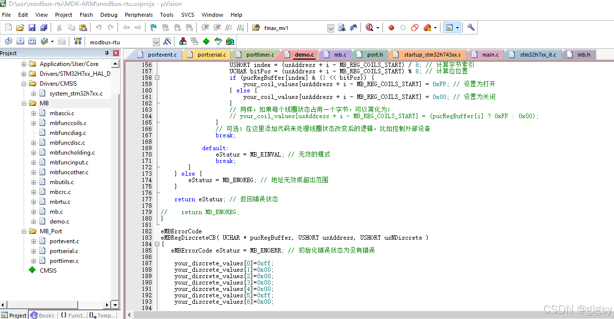
硬件接口方面结束之后就可以开始写功能了,在MB–>demo.c中有功能示例,我们根据功能示例来修改对应的功能并使能modbus。
eMBRegInputCB()  //读取输入寄存器
eMBRegHoldingCB() //保持寄存器操作函数
eMBRegCoilsCB()    //线圈操作函数
eMBRegDiscreteCB()  //离散寄存器操作函数
/* ----------------------- Modbus includes ----------------------------------*/
#include "mb.h"
#include "mbport.h"
/* ----------------------- Defines ------------------------------------------*/
//输入寄存器起始地址
#define REG_INPUT_START 0x0000
//输入寄存器数量
#define REG_INPUT_NREGS 8
//保持寄存器起始地址
#define REG_HOLDING_START 0x0000
//保持寄存器数量
#define REG_HOLDING_NREGS 8
//线圈起始地址
#define REG_COILS_START 0x0000
//线圈数量
#define REG_COILS_SIZE 16
//开关寄存器起始地址
#define REG_DISCRETE_START 0x0000
//开关寄存器数量
#define REG_DISCRETE_SIZE 16
/* Private variables ---------------------------------------------------------*/
//输入寄存器内容
uint16_t usRegInputBuf[REG_INPUT_NREGS] = {0x1000,0x1001,0x1002,0x1003,0x1004,0x1005,0x1006,0x1007};
//输入寄存器起始地址
uint16_t usRegInputStart = REG_INPUT_START;
//保持寄存器内容
uint16_t usRegHoldingBuf[REG_HOLDING_NREGS] = {0x147b,0x3f8e,0x147b,0x400e,0x1eb8,0x4055,0x147b,0x408e};
//保持寄存器起始地址
uint16_t usRegHoldingStart = REG_HOLDING_START;
//线圈状态
uint8_t ucRegCoilsBuf[REG_COILS_SIZE / 8] = {0x03,0x02};
//开关输入状态
uint8_t ucRegDiscreteBuf[REG_DISCRETE_SIZE / 8] = {0x03,0x02};
/****************************************************************************
* 名 称:eMBRegInputCB
* 功 能:读取输入寄存器,对应功能码是 04 eMBFuncReadInputRegister
* 入口参数:pucRegBuffer: 数据缓存区,用于响应主机
* usAddress: 寄存器地址
* usNRegs: 要读取的寄存器个数
* 出口参数:
* 注 意:上位机发来的 帧格式是: SlaveAddr(1 Byte)+FuncCode(1 Byte)
* +StartAddrHiByte(1 Byte)+StartAddrLoByte(1 Byte)
* +LenAddrHiByte(1 Byte)+LenAddrLoByte(1 Byte)+
* +CRCAddrHiByte(1 Byte)+CRCAddrLoByte(1 Byte)
* 3 区
****************************************************************************/
eMBErrorCode
eMBRegInputCB( UCHAR * pucRegBuffer, USHORT usAddress, USHORT usNRegs )
{
eMBErrorCode eStatus = MB_ENOERR;
int iRegIndex;
if( ( usAddress >= REG_INPUT_START ) && ( usAddress + usNRegs <= REG_INPUT_START + REG_INPUT_NREGS ) )
{
iRegIndex = ( int )( usAddress - usRegInputStart );
while( usNRegs > 0 )
{
*pucRegBuffer++ = ( UCHAR )( usRegInputBuf[iRegIndex] >> 8 );
*pucRegBuffer++ = ( UCHAR )( usRegInputBuf[iRegIndex] & 0xFF );
iRegIndex++;
usNRegs--;
}
}
else
{
eStatus = MB_ENOREG;
}
return eStatus;
}
/****************************************************************************
* 名 称:eMBRegHoldingCB
* 功 能:对应功能码有:06 写保持寄存器 eMBFuncWriteHoldingRegister
* 16 写多个保持寄存器 eMBFuncWriteMultipleHoldingRegister
* 03 读保持寄存器 eMBFuncReadHoldingRegister
* 23 读写多个保持寄存器 eMBFuncReadWriteMultipleHoldingRegister
* 入口参数:pucRegBuffer: 数据缓存区,用于响应主机
* usAddress: 寄存器地址
* usNRegs: 要读写的寄存器个数
* eMode: 功能码
* 出口参数:
* 注 意:4 区
****************************************************************************/
eMBErrorCode
eMBRegHoldingCB( UCHAR * pucRegBuffer, USHORT usAddress, USHORT usNRegs, eMBRegisterMode eMode )
{
eMBErrorCode eStatus = MB_ENOERR;
int iRegIndex;
if((usAddress >= REG_HOLDING_START)&&((usAddress+usNRegs) <= (REG_HOLDING_START + REG_HOLDING_NREGS)))
{
iRegIndex = (int)(usAddress - usRegHoldingStart);
switch(eMode)
{
case MB_REG_READ://读 MB_REG_READ = 0
while(usNRegs > 0)
{
*pucRegBuffer++ = (uint8_t)(usRegHoldingBuf[iRegIndex] >> 8);
*pucRegBuffer++ = (uint8_t)(usRegHoldingBuf[iRegIndex] & 0xFF);
iRegIndex++;
usNRegs--;
}
break;
case MB_REG_WRITE://写 MB_REG_WRITE = 0
while(usNRegs > 0)
{
usRegHoldingBuf[iRegIndex] = *pucRegBuffer++ << 8;
usRegHoldingBuf[iRegIndex] |= *pucRegBuffer++;
iRegIndex++;
usNRegs--;
}
}
}
else//错误
{
eStatus = MB_ENOREG;
}
return eStatus;
}
extern void xMBUtilSetBits( UCHAR * ucByteBuf, USHORT usBitOffset, UCHAR ucNBits,
UCHAR ucValue );
extern UCHAR xMBUtilGetBits( UCHAR * ucByteBuf, USHORT usBitOffset, UCHAR ucNBits );
/****************************************************************************
* 名 称:eMBRegCoilsCB
* 功 能:对应功能码有:01 读线圈 eMBFuncReadCoils
* 05 写线圈 eMBFuncWriteCoil
* 15 写多个线圈 eMBFuncWriteMultipleCoils
* 入口参数:pucRegBuffer: 数据缓存区,用于响应主机
* usAddress: 线圈地址
* usNCoils: 要读写的线圈个数
* eMode: 功能码
* 出口参数:
* 注 意:如继电器
* 0 区
****************************************************************************/
eMBErrorCode
eMBRegCoilsCB( UCHAR * pucRegBuffer, USHORT usAddress, USHORT usNCoils,
eMBRegisterMode eMode )
{
//错误状态
eMBErrorCode eStatus = MB_ENOERR;
//寄存器个数
int16_t iNCoils = ( int16_t )usNCoils;
//寄存器偏移量
int16_t usBitOffset;
//检查寄存器是否在指定范围内
if( ( (int16_t)usAddress >= REG_COILS_START ) &&
( usAddress + usNCoils <= REG_COILS_START + REG_COILS_SIZE ) )
{
//计算寄存器偏移量
usBitOffset = ( int16_t )( usAddress - REG_COILS_START );
switch ( eMode )
{
//读操作
case MB_REG_READ:
while( iNCoils > 0 )
{
*pucRegBuffer++ = xMBUtilGetBits( ucRegCoilsBuf, usBitOffset,
( uint8_t )( iNCoils > 8 ? 8 : iNCoils ) );
iNCoils -= 8;
usBitOffset += 8;
}
break;
//写操作
case MB_REG_WRITE:
while( iNCoils > 0 )
{
xMBUtilSetBits( ucRegCoilsBuf, usBitOffset,
( uint8_t )( iNCoils > 8 ? 8 : iNCoils ),
*pucRegBuffer++ );
iNCoils -= 8;
usBitOffset += 8;
}
break;
}
}
else
{
eStatus = MB_ENOREG;
}
return eStatus;
}
/****************************************************************************
* 名 称:eMBRegDiscreteCB
* 功 能:读取离散寄存器,对应功能码有:02 读离散寄存器 eMBFuncReadDiscreteInputs
* 入口参数:pucRegBuffer: 数据缓存区,用于响应主机
* usAddress: 寄存器地址
* usNDiscrete: 要读取的寄存器个数
* 出口参数:
* 注 意:1 区
****************************************************************************/
eMBErrorCode
eMBRegDiscreteCB( UCHAR * pucRegBuffer, USHORT usAddress, USHORT usNDiscrete )
{
//错误状态
eMBErrorCode eStatus = MB_ENOERR;
//操作寄存器个数
int16_t iNDiscrete = ( int16_t )usNDiscrete;
//偏移量
uint16_t usBitOffset;
//判断寄存器时候再制定范围内
if( ( (int16_t)usAddress >= REG_DISCRETE_START ) &&
( usAddress + usNDiscrete <= REG_DISCRETE_START + REG_DISCRETE_SIZE ) )
{
//获得偏移量
usBitOffset = ( uint16_t )( usAddress - REG_DISCRETE_START );
while( iNDiscrete > 0 )
{
*pucRegBuffer++ = xMBUtilGetBits( ucRegDiscreteBuf, usBitOffset,
( uint8_t)( iNDiscrete > 8 ? 8 : iNDiscrete ) );
iNDiscrete -= 8;
usBitOffset += 8;
}
}
else
{
eStatus = MB_ENOREG;
}
return eStatus;
}
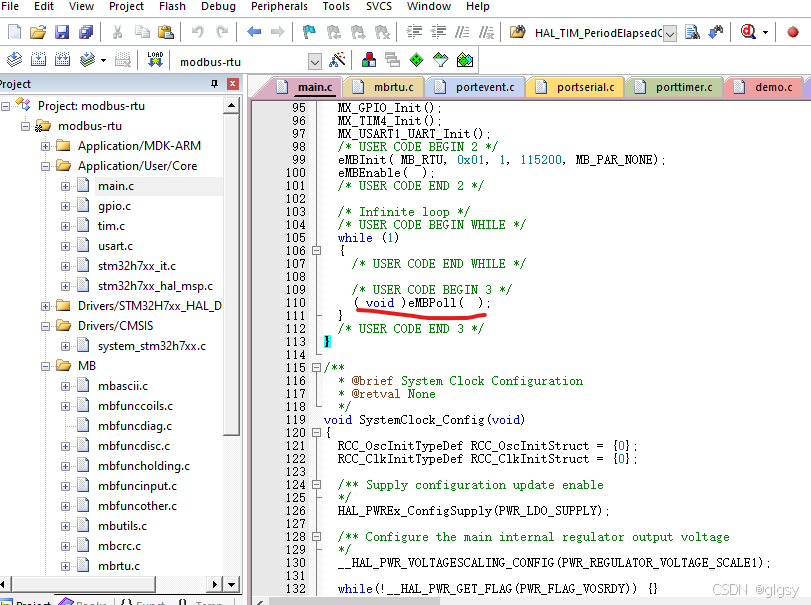
在main.c中加入
eMBInit() //初始化modbus
eMBEnable() //使能modbus
eMbPoll() //查询事件状态
eMBInit( eMBMode eMode, UCHAR ucSlaveAddress, UCHAR ucPort, ULONG ulBaudRate, eMBParity eParity )
eMode: modbus模式 MB_RTU、MB_ASCII
ucSlaveAddress: 从机地址
ucPort: 连接的端口号(如串口连接电脑的端口号,当前测试被忽略了无效)
ulBaudRate: 连接串口的波特率
eParity: 校验方式(MB_PAR_NONE、MB_PAR_ODD、MB_PAR_EVEN)/**
* 第一个参数:(eMode)MB_RTU,表示freeModbus初始化模式为Modbus RTU
* 第二个参数:(ucSlaveAddress)0x01,表示从机地址为0x01;
* 第三个参数:(ucPort)0x01,使用串口1;
* 第四个参数:(ulBaudRate)115200,表示波特率为115200;
* 第五个参数:(eParity)MB_PAR_NONE,表示无校验码;
**/
eMBInit( MB_RTU, 0x01, 1, 115200, MB_PAR_NONE);
eMBEnable( );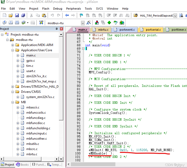
mbrtu.c文件中加入
eMBErrorCode
eMBRTUSend( UCHAR ucSlaveAddress, const UCHAR * pucFrame, USHORT usLength )
{
    eMBErrorCode    eStatus = MB_ENOERR;
    USHORT          usCRC16;

    ENTER_CRITICAL_SECTION(  );

    /* Check if the receiver is still in idle state. If not we where to
     * slow with processing the received frame and the master sent another
     * frame on the network. We have to abort sending the frame.
     */
    if( eRcvState == STATE_RX_IDLE )
    {
        /* First byte before the Modbus-PDU is the slave address. */
        pucSndBufferCur = ( UCHAR * ) pucFrame - 1;
        usSndBufferCount = 1;

        /* Now copy the Modbus-PDU into the Modbus-Serial-Line-PDU. */
        pucSndBufferCur[MB_SER_PDU_ADDR_OFF] = ucSlaveAddress;
        usSndBufferCount += usLength;

        /* Calculate CRC16 checksum for Modbus-Serial-Line-PDU. */
        usCRC16 = usMBCRC16( ( UCHAR * ) pucSndBufferCur, usSndBufferCount );
        ucRTUBuf[usSndBufferCount++] = ( UCHAR )( usCRC16 & 0xFF );
        ucRTUBuf[usSndBufferCount++] = ( UCHAR )( usCRC16 >> 8 );

        /* Activate the transmitter. */
        eSndState = STATE_TX_XMIT;

		//修改了从这里往下
		//启动第一次发送,这样才可以进入发送完成中断
        xMBPortSerialPutByte( ( CHAR )*pucSndBufferCur );
        pucSndBufferCur++;  /* next byte in sendbuffer. */
        usSndBufferCount--;

        vMBPortSerialEnable( FALSE, TRUE );
    }
    else
    {
        eStatus = MB_EIO;
    }
    EXIT_CRITICAL_SECTION(  );
    return eStatus;
}
以下文件中的usRegAddress++会导致读写地址自增不从0号地址开始,可以将以下文件中的usRegAddress++注释掉
mbfunccoils.c
mbfuncdisc.c
mbfuncholding.c
mbfuncinput.c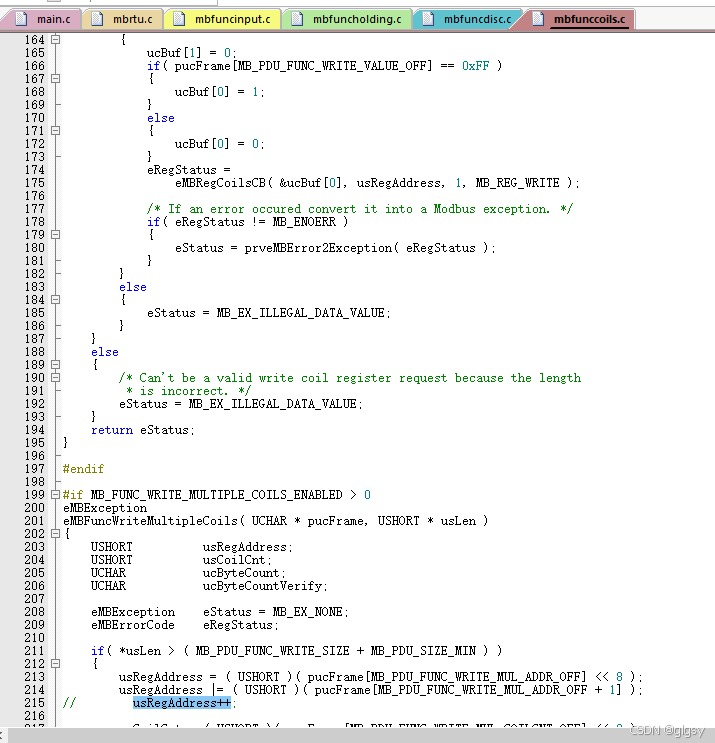
在mbconfig.h文件中把当前使用的为ModBus RTU 将默认的ModBus ASCII 取消
/*! \brief If Modbus ASCII support is enabled. */
#define MB_ASCII_ENABLED                        (  0 )

/*! \brief If Modbus RTU support is enabled. */
#define MB_RTU_ENABLED                          (  1 )

/*! \brief If Modbus TCP support is enabled. */
#define MB_TCP_ENABLED                          (  0 )

/*! \brief The character timeout value for Modbus ASCII.
*
* The character timeout value is not fixed for Modbus ASCII and is therefore
* a configuration option. It should be set to the maximum expected delay
* time of the network.
*/
#define MB_ASCII_TIMEOUT_SEC                    (  0 )


 9126
9126

 被折叠的 条评论
为什么被折叠?
被折叠的 条评论
为什么被折叠?
 到【灌水乐园】发言


