


正文共:3707 字 11 图,预估阅读时间:10 分钟
实际应用场景中,如果和SD-WAN结合起来,很少会使用这种两端直连的场景(IKE主模式及预共享密钥认证配置)。或者说,两个子网的互通可能是通过第三台设备来实现的。举例说明一下,上次的实验中,RTB和RTC是直接建立的IPsec隧道,而实际应用中,有可能是RTA和RTB、RTC之间分别建立IPsec隧道,再实现RTB和RTC两台设备下挂子网的互通。

组网需求

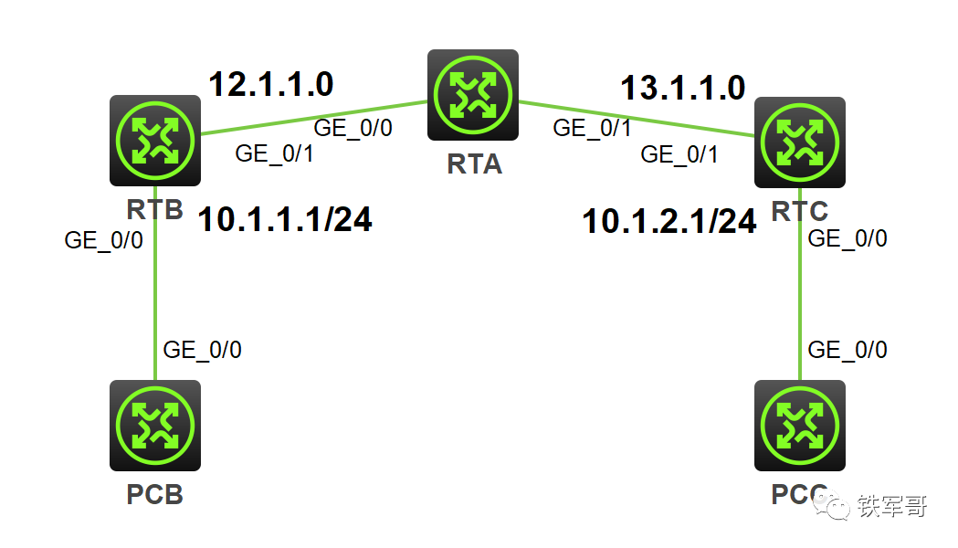
某SD-WAN使用场景,组网使用3台路由器。图中RTA为总部设备,RTB、RTC为分支设备,RTA和RTB、RTC之间分别建立IPsec隧道,对PCB所在的子网(10.1.1.0/24)与PCC所在的子网(10.1.2.0/24)之间的数据流进行安全保护。具体要求如下:
· 封装形式为隧道模式。
· 安全协议采用ESP协议。
· 加密算法采用128比特的AES,认证算法采用HMAC-SHA1。
· IKE协商方式建立IPsec SA。

组网图

采用IKE方式建立保护IPv4报文的IPsec隧道。

配置步骤


配置思路
RTB和RTC和RTA建立IPsec隧道时,保护的数据流和上次是一样的,都是两端的私网地址。不同的是,两端私网的互访流量会在RTA上解封装,这样一来,RTA上就要增加到两端内网的路由信息。
这么一来,配置是不是就清晰了,直接上配置。

配置RTA
#
sysname RTA
#
interface GigabitEthernet0/0
 ip address 12.1.1.1 255.255.255.0
 ipsec apply policy map2
#
interface GigabitEthernet0/1
 ip address 13.1.1.1 255.255.255.0
 ipsec apply policy map3
#
ip route-static 10.1.1.0 24 12.1.1.2
ip route-static 10.1.2.0 24 13.1.1.3
#
acl advanced 3401
 rule 0 permit ip source 10.1.1.0 0.0.0.255 destination 10.1.2.0 0.0.0.255
 rule 5 permit ip source 10.1.2.0 0.0.0.255 destination 10.1.1.0 0.0.0.255
#
ipsec transform-set tran1
 esp encryption-algorithm aes-cbc-128
 esp authentication-algorithm sha1
#
ipsec policy map2 10 isakmp
 transform-set tran1
 security acl 3401
 local-address 12.1.1.1
 remote-address 12.1.1.2
 ike-profile pro2
#
ipsec policy map3 10 isakmp
 transform-set tran1
 security acl 3401
 local-address 13.1.1.1
 remote-address 13.1.1.3
 ike-profile pro3
#
ike profile pro2
 keychain key2
 match remote identity address 12.1.1.2 255.255.255.0
#
ike profile pro3
 keychain key3
 match remote identity address 13.1.1.3 255.255.255.0
#
ike keychain key2
 pre-shared-key address 12.1.1.2 255.255.255.0 key simple qwe123
#
ike keychain key3
 pre-shared-key address 13.1.1.3 255.255.255.0 key simple qwe123
配置RTB
#
sysname RTB
#
interface GigabitEthernet0/0
 ip address 10.1.1.1 255.255.255.0
#
interface GigabitEthernet0/1
 ip address 12.1.1.2 255.255.255.0
 ipsec apply policy map1
#
ip route-static 10.1.2.0 24 12.1.1.1
ip route-static 13.1.1.0 24 12.1.1.1
#
acl advanced 3401
 rule 0 permit ip source 10.1.1.0 0.0.0.255 destination 10.1.2.0 0.0.0.255
#
ipsec transform-set tran1
 esp encryption-algorithm aes-cbc-128
 esp authentication-algorithm sha1
#
ipsec policy map1 10 isakmp
 transform-set tran1
 security acl 3401
 local-address 12.1.1.2
 remote-address 12.1.1.1
 ike-profile pro1
#
ike profile pro1
 keychain key1
 match remote identity address 12.1.1.1 255.255.255.0
#
ike keychain key1
 pre-shared-key address 12.1.1.1 255.255.255.0 key simple qwe123
配置RTC
#
sysname RTC
#
interface GigabitEthernet0/0
 ip address 10.1.2.1 255.255.255.0
#
interface GigabitEthernet0/1
 ip address 13.1.1.3 255.255.255.0
 ipsec apply policy map1
#
ip route-static 10.1.1.0 24 13.1.1.1
ip route-static 12.1.1.0 24 13.1.1.1
#
acl advanced 3401
 rule 0 permit ip source 10.1.2.0 0.0.0.255 destination 10.1.1.0 0.0.0.255
#
ipsec transform-set tran1
 esp encryption-algorithm aes-cbc-128
 esp authentication-algorithm sha1
#
ipsec policy map1 10 isakmp
 transform-set tran1
 security acl 3401
 local-address 13.1.1.3
 remote-address 13.1.1.1
 ike-profile pro1
#
ike profile pro1
 keychain key1
 match remote identity address 13.1.1.1 255.255.255.0
#
ike keychain key1
 pre-shared-key address 13.1.1.1 255.255.255.0 key simple qwe123
验证配置

以上配置完成后,使用10.1.2.2主动访问10.1.1.2,来触发IKE进行IPsec SA的协商。
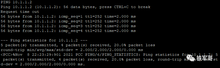
IKE成功协商出IPsec SA后,子网10.1.1.0/24与子网10.1.2.0/24之间数据流的传输将受到IPsec SA的保护。
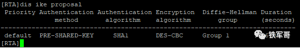
可通过命令查看到RTA的IKE提议信息。
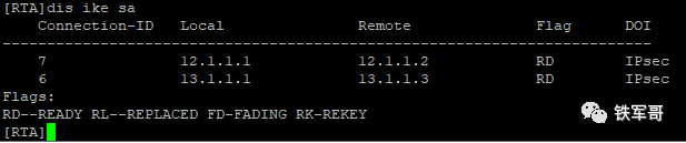
可通过命令查看到RTA上IKE第一阶段协商成功后生成的IKE SA信息。
如果带上verbose,可以看到更多的详细信息。
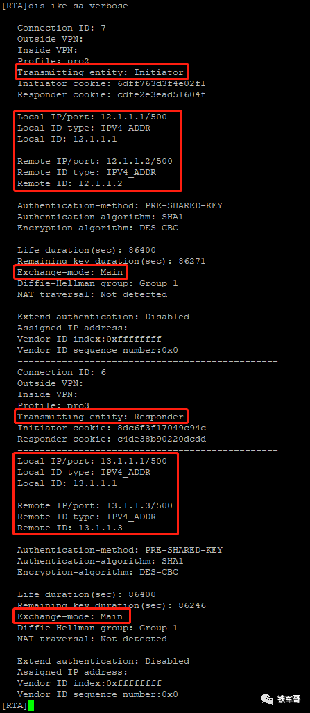
和上次不同,我们可以看到RTA既是发起者又是响应者。我发起访问的流量是从RTC过来的,所以对于RTA来讲,RTC是发起者,RTA是响应者;当流量去往RTB时,RTA对于RTB来讲就又是发起者了。
同样的,两段IKE SA中本地和对端的端口号都是500,也能看到1阶段的交换模式是主模式。
通过命令查看到协商生成的IPsec SA。
display ipsec sa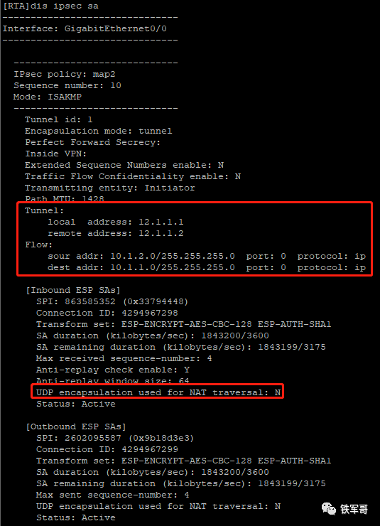
上面是RTA和RTB之间的SA,下面是RTA和RTC之间的SA。
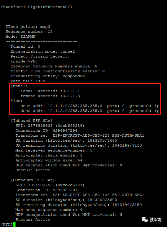
可以看到,这次PCB和PCC之间的互访是经过了两段隧道。我们在RTA上debug一下PING报文。
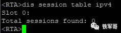
竟然没有显示,也看不到会话表项。
难道不会进内核?那是不是不需要配置RTA到两端内网的明细路由?删掉相关配置试一下。
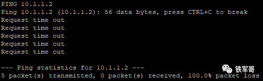
删掉路由之后,两端就不通了,恢复配置就正常,证明路由确实是有必要的。
好吧,我忘了debug看不到过路的ICMP报文了。
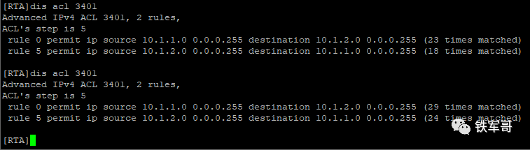
但是通过ACL的匹配次数,可以看到报文确实是一进一出的。(差的5次是删掉路由之后没通的5个)
查看SA建立过程,抓包截图如下:
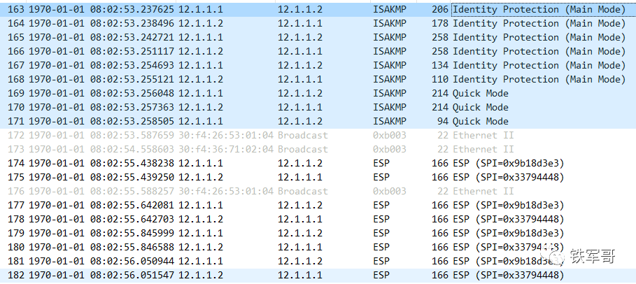
OK,没有问题。
你知道SD-WAN是怎么工作的了不?

长按二维码
关注我们吧


 1455
1455


 被折叠的 条评论
为什么被折叠?
被折叠的 条评论
为什么被折叠?
 到【灌水乐园】发言


