


允许访问执行装配操作的函数; 例如,添加新组件、添加配合条件、隐藏和爆炸组件。
属性
| Name | Description | 备注 |
| EnableAssemblyRebuild | Gets or sets whether to suspend the rebuild of the assembly. | 获取或设置是否挂起程序集的重建。 |
| EnablePresentation | Gets or sets whether the assembly is in presentation mode. | 获取或设置程序集是否处于演示模式。 |
| InterferenceDetectionManager | Gets the Interference Detection manager, which allows you to run interference detection on an assembly to determine whether components interfere with each other. | 获取干涉检测管理器,它允许您在装配上运行干涉检测以确定组件是否相互干涉。 |
| LargeDesignReviewTransparencyLevel | Gets or sets the transparency level of unmodified components in the graphics area of this assembly opened in Large Design Review mode. | 获取或设置在大型设计审阅模式下打开的此装配的图形区域中未修改组件的透明度级别。 |
| LargeDesignReviewTransparencyLevelDynamic | Gets or sets whether to dynamically modify the transparency level of unmodified components in the graphics area when the transparency level slider is moved on the Filter Modified Components PropertyManager page. | 获取或设置在过滤修改的零部件 PropertyManager 页面上移动透明度级别滑块时,是否动态修改图形区域中未修改零部件的透明度级别。 |
| LargeDesignReviewTransparencyLevelEnabled | Gets or sets whether transparency levels are activated for unmodified components in the graphics area for this assembly opened in Large Design Review mode | 获取或设置是否为在大型设计审阅模式下打开的此装配体的图形区域中未修改的组件激活透明度级别 |
方法
| Name | Description | 备注 |
| ActivateGroundPlane | Activates the ground plane for the specified configurations. | 激活指定配置的ground plane。 |
| AddComponent5 | Adds the specified component for the specified configuration options to this assembly. | 将指定配置选项的指定组件添加到此程序集。 |
| AddComponentConfiguration | Adds a new configuration for the last selected assembly component. | 为最后选择的装配体元件添加新配置。 |
| AddComponents3 | Adds multiple components to the assembly. | 将多个零部件添加到装配体。 |
| AddConcentricMateWithTolerance | Adds a misaligned concentric mate to this assembly. | 向该装配体添加未对齐的同心配合。 |
| AddDistanceMate | Adds a distance mate to this assembly. | 向该装配体添加距离配合。 |
| AddPipePenetration | Penetrates the adjacent fitting or pipe with the pipe that ends at the selected sketch point. | 使用终止于选定草图点的管道穿透相邻的管件或管道。 |
| AddPipingFitting | Adds a pipe fitting to the current piping assembly. | 将管件添加到当前管道组件。 |
| AddSmartComponent | Adds the specified component at the specified coordinates as a Smart Component to this assembly. | 将指定坐标处的指定组件作为智能组件添加到此程序集。 |
| AddToFeatureScope | Adds a component to the scope of the currently selected assembly feature. | 将零部件添加到当前选定的装配特征的范围内。 |
| AutoAngleAxis | Automatically detect the axis for an angle mate. | 自动检测角度配合的轴。 |
| AutoExplode | Automatically generates an exploded view of the current assembly configuration. | 自动生成当前装配体配置的分解图。 |
| CompConfigProperties6 | Sets the properties for the selected component in the specified configuration. | 在指定的配置中设置所选组件的属性。 |
| CopyWithMates2 | Copies one or more components with mates in this assembly. | 在该装配体中复制一个或多个带有配合的零部件。 |
| CreateExplodedView | Creates an explode view of the active assembly configuration. | 创建活动装配体配置的爆炸视图。 |
| CreateMate | Creates a mate with the specified feature data object. | 使用指定的特征数据对象创建配合。 |
| CreateMateData | Creates a mate feature data object for the specified mate type. | 为指定的配合类型创建配合特征数据对象。 |
| CreateSmartComponent | Creates a Smart Component. | 创建智能组件。 |
| CreateSpeedPak | Creates the specified type of SpeedPak for the active configurations of the selected subassemblies in this assembly. | 为该装配中选定子装配的活动配置创建指定类型的 SpeedPak。 |
| DeleteSelections | Delete either the selected components of a subassembly or the subassembly of the selected component. | 删除子装配体的选定零部件或选定零部件的子装配体。 |
| DissolveComponentPattern | Dissolves the selected component patterns. | 解散选定的组件阵列。 |
| DissolveSubAssembly | Dissolves the selected subassembly in this assembly. | 解散此装配中的选定子装配。 |
| EditAssembly | Switches back to the assembly document for editing. | 切换回装配体文档进行编辑。 |
| EditConcentricMate | Edits a misaligned concentric mate. | 编辑未对齐的同心配合。 |
| EditDistanceMate | Edits a distance mate. | 编辑距离配合。 |
| EditPart2 | Edits the selected part within the context of an assembly. | 在装配的上下文中编辑选定的零件。 |
| ExitIsolate | Exits isolating the selected components and returns the assembly to its original display state. | 退出隔离选定的组件并将组件返回到其原始显示状态。 |
| FeatureByName | Returns the IFeature object for the named feature in the assembly. | 返回装配中命名特征的 IFeature 对象。 |
| FileDeriveComponentPart | Creates a new part document from the currently selected assembly component. | 从当前选定的装配体元件创建一个新的零件文档。 |
| FixComponent | Fixes the selected component; i.e., makes it immovable. | 固定选定的组件;即,使其不可移动。 |
| ForceUpdateElectricalData2 | Forces an update of electrical data. | 强制更新电气数据。 |
| GetActiveGroundPlane | Gets the active ground plane for the specified configurations. | 获取指定配置的活动 ground plane。 |
| GetAdvancedSelection | Gets the advanced component selection. | 获取高级组件选择。 |
| GetBox | Gets the bounding box. | 获取边界框。 |
| GetComponentByID | Gets a top-level assembly component using its component ID. | 使用其组件 ID 获取顶级程序集组件。 |
| GetComponentByName | Gets the specified top-level assembly component. | 获取指定的顶级程序集组件。 |
| GetComponentCount | Gets the number of components in the active configuration of this assembly. | 获取此程序集的活动配置中的组件数。 |
| GetComponents | Gets all of the components in the active configuration of this assembly. | 获取此程序集的活动配置中的所有组件。 |
| GetDragOperator | Gets the drag operator for dynamic drag operations in this assembly. | 获取此程序集中动态拖动操作的拖动操作符。 |
| GetDroppedAtEntity | Gets a pointer to the entity where a file is dropped into this assembly. | 获取指向将文件放入此程序集中的实体的指针。 |
| GetEditTarget | Gets the model document that is currently being edited. | 获取当前正在编辑的模型文档。 |
| GetEditTargetComponent | Gets the component that is currently being edited. | 获取当前正在编辑的组件。 |
| GetExplodedViewConfigurationName | Gets the name of the configuration for the specified exploded view. | 获取指定爆炸视图的配置名称。 |
| GetExplodedViewCount2 | Gets the number of exploded views in the specified configuration. | 获取指定配置中的爆炸视图数。 |
| GetExplodedViewNames2 | Gets the names of the exploded views in the specified configuration. | 获取指定配置中爆炸视图的名称。 |
| GetFeatureScope | Gets the components affected by this feature. | 获取受此功能影响的组件。 |
| GetFeatureScopeCount | Gets the number of components affected by this feature. | 获取受此功能影响的组件数。 |
| GetLightWeightComponentCount | Gets the number of lightweight components in the assembly. | 获取装配中轻量化零部件的数量。 |
| GetRouteManager | Gets the SOLIDWORKS Routing API. | 获取 SOLIDWORKS Routing API。 |
| GetUnloadedComponentNames | Gets the unloaded components' paths, referenced configuration names, reasons why they are unloaded, document types, and names. | 获取卸载组件的路径、引用的配置名称、卸载它们的原因、文档类型和名称。 |
| GetVisibleComponentsInView | Gets a list of visible components in this assembly to save as solid bodies. | 获取此装配中要保存为实体的可见零部件列表。 |
| GetVisibleComponentsInViewCount | Gets the number of visible components in this assembly. | 获取此装配中可见零部件的数量。 |
| HasUnloadedComponents | Gets whether this assembly has hidden or suppressed unloaded components. | 获取此装配体是否隐藏或压缩了卸载的零部件。 |
| IAddComponents3 | Adds multiple components to the assembly. | 将多个零部件添加到装配体。 |
| IFeatureByName | Returns the IFeature object for the named feature in the assembly. | 返回装配中命名特征的 IFeature 对象。 |
| IGetBox | Gets the bounding box. | 获取边界框。 |
| IGetComponents | Gets all of the components in the active configuration of this assembly. | 获取此程序集的活动配置中的所有组件。 |
| IGetDragOperator | Gets the drag operator for dynamic drag operations in this assembly. | 获取此程序集中动态拖动操作的拖动操作符。 |
| IGetEditTarget2 | Gets the model document that is currently being edited. | 获取当前正在编辑的模型文档。 |
| IGetFeatureScope | Gets the components affected by this feature. | 获取受此功能影响的组件。 |
| IGetVisibleComponentsInView | Gets a list of visible components in this assembly to save as solid bodies. | 获取此装配中要保存为实体的可见零部件列表。 |
| InsertCavity4 | Inserts a cavity to the active part using a selected component. | 使用选定的零部件将型腔插入到活动零件中。 |
| InsertEnvelope | Adds an envelope in the specified configuration name in this assembly. | 在此程序集中的指定配置名称中添加一个封套。 |
| InsertJoin2 | Constructs a feature from merged selected components. | 从合并的选定组件构造一个特征。 |
| InsertLoadReference | Creates a mate load reference to the specified or selected mate. | 创建对指定或选定配合的配合载荷参考。 |
| InsertNewAssembly | Creates a new virtual sub-assembly and optionally saves it to the specified file. | 创建一个新的虚拟子装配体,并可选择将其保存到指定的文件中。 |
| InsertNewPart2 | Inserts a new part on the specified face or plane. | 在指定的面或平面上插入新零件。 |
| InsertNewVirtualAssembly | Creates a new assembly from this assembly and saves it internally as a virtual component. | 从该装配体创建一个新装配体,并将其在内部保存为虚拟元件。 |
| InsertNewVirtualPart | Creates a new part in the context of an assembly and saves the part internally in the assembly file as a virtual component. | 在装配体的上下文中创建新零件,并将零件在装配体文件内部保存为虚拟零部件。 |
| IReorderComponents | Moves components to a different location in the FeatureManager tree. | 将零部件移动到 FeatureManager 树中的不同位置。 |
| IReorganizeComponents | Reorganizes an assembly's structure by moving the selected components to the selected assembly or sub-assembly. | 通过将选定的零部件移动到选定的装配体或子装配体来重新组织装配体的结构。 |
| IsComponentTreeValid | Checks the validity of the component tree for this assembly. | 检查此装配的零部件树的有效性。 |
| ISetComponentState | Sets the suppression state for the specified components. | 设置指定组件的压缩状态。 |
| ISetComponentVisibility | Hides or shows the selected component in the specified configurations in this assembly document. | 在此装配体文档的指定配置中隐藏或显示选定的零部件。 |
| Isolate | Isolates the selected components. | 隔离选定的组件。 |
| IsRouteAssembly | Gets whether the assembly document is a routing assembly. | 获取装配体文档是否为布线装配体。 |
| LightweightAllResolved | Sets to lightweight all resolved child components of the selected components. | 将选定组件的所有已解析子组件设置为轻化。 |
| MakeAssemblyFromSelectedComponents | Creates a new assembly comprised of the selected components of this assembly. | 创建一个包含此组件的选定组件的新组件。 |
| MakeIndependent | Makes the selected component independent. | 使选定的组件孤立。 |
| MakeLightWeight | Sets the selected components to lightweight. | 将选定的组件设置为轻量化。 |
| MirrorComponents3 | Mirrors the specified components in this assembly. | 镜像此装配中的指定零部件。 |
| RemoveFromFeatureScope | Removes a component from the scope of the currently selected assembly feature. | 从当前选定的装配特征的范围中删除一个零部件。 |
| ReorderComponents | Moves components to a different location in the FeatureManager design tree. | 将零部件移动到 FeatureManager 设计树中的不同位置。 |
| ReorganizeComponents | Reorganizes an assembly's structure by moving the selected components to the selected assembly or sub-assembly. | 通过将选定的零部件移动到选定的装配体或子装配体来重新组织装配体的结构。 |
| ReplaceComponents2 | Replaces one or more selected components with another model. | 用另一种模型替换一个或多个选定的组件。 |
| ResolveAllLightweight | Resolves all lightweight child components of the selected components | 解析选定组件的所有轻量级子组件 |
| ResolveAllLightWeightComponents | Resolves the lightweight components in this assembly. | 解决此装配中的轻量化零部件。 |
| ResolveOutOfDateLightWeightComponents | Resolves the selected out-of-date lightweight component, and any out-of-date lightweight sub-components, in the assembly. | 解析装配体中选定的过时轻化零部件和任何过时的轻化子零部件。 |
| RotateComponent | Displays the Rotate Component PropertyManager page. | 显示旋转零部件 PropertyManager 页面。 |
| RotateComponentAxis | Rotates the component axis by a fixed amount. | 以固定量旋转组件轴。 |
| SaveIsolate | Saves the display characteristics of the isolated components to a new display state. | 将隔离组件的显示特性保存到新的显示状态。 |
| SelectComponentsBySize | Selects assembly components by percent of assembly size. | 按装配体尺寸的百分比选择装配体零部件。 |
| SelectiveOpen | Selectively opens the components of an assembly that is opened in Large Design Review mode. | 有选择地打开在大型设计审查模式下打开的组件的组件。 |
| SetComponentState | Sets the suppression state for the specified components. | 设置指定组件的压缩状态。 |
| SetComponentSuppression | Suppresses, resolves, or sets to lightweight selected components of this assembly in the active configuration only. | 仅在活动配置中压缩、解析或设置此装配体的轻量化选定零部件。 |
| SetComponentTransparent | Enables or disables transparency on the selected components. | 启用或禁用选定组件的透明度。 |
| SetComponentVisibility | Hides or shows the selected component in the specified configurations in this assembly document. | 在此装配体文档的指定配置中隐藏或显示选定的零部件。 |
| SetDroppedFileConfigName | Sets the configuration name for the recently dropped file. | 为最近删除的文件设置配置名称。 |
| SetDroppedFileFeatureName | Sets the name of the feature for the recently dropped file. | 为最近删除的文件设置功能的名称。 |
| SetDroppedFileName | Sets the new file name for a recently dropped file. | 为最近删除的文件设置新文件名。 |
| SetIsolateVisibility | Sets the display characteristics of all of the components not selected to isolate. | 设置所有未选择隔离的组件的显示特性。 |
| SetSpeedPakConfigurations | Sets the configurations in the selected subassemblies to which to apply SpeedPak in this assembly. | 设置选定子装配体中的配置,以在该装配体中应用 SpeedPak。 |
| SetSpeedPakToParent | Switches the selected subassemblies from the SpeedPak configuration to the parent configuration of the SpeedPak configuration. | 将选定的子装配从 SpeedPak 配置切换到 SpeedPak 配置的父配置。 |
| ShowExploded2 | Displays the specified exploded view for the current assembly configuration. | 显示当前装配体配置的指定爆炸视图。 |
| TemporaryFixGroup | Temporarily fix or group selected components during such operations as drag, move, rotate, etc. | 在诸如拖动、移动、旋转等操作期间临时固定或分组选定的组件。 |
| TemporaryFixGroupExit | Changes components that were temporarily fixed or grouped back to floating or ungrouped after such operations as drag, move, rotate, etc. | 在拖动、移动、旋转等操作后,将临时固定或分组的组件更改回浮动或取消分组。 |
| ToolsCheckInterference2 | Checks for interference between parts in this assembly. | 检查此装配中零件之间的干涉。 |
| TranslateComponent | Displays the Move Component PropertyManager page. | 显示移动零部件 PropertyManager 页面。 |
| UnfixComponent | Floats the selected component; i.e., makes it movable. | 浮动选中的组件;即,使其可移动。 |
| UngroupComponents | Ungroups the grouped components in the selected folder in the FeatureManager design tree. | 在 FeatureManager 设计树的选定文件夹中取消分组的零部件。 |
| UpdateBox | Updates the bounding box for this assembly. | 更新此程序集的边界框。 |
| UpdateFeatureScope | Updates the feature scope and rebuilds the currently selected assembly feature. | 更新特征范围并重建当前选定的装配特征。 |
| UpdateSpeedPak | Updates out-of-date SpeedPak configurations for the selected subassemblies. | 更新选定子装配体的过时 SpeedPak 配置。 |
| UpdateToolboxComponent | Updates SOLIDWORKS Toolbox components in the specified assembly level using the current information in Toolbox settings. | 使用 Toolbox 设置中的当前信息更新指定装配体级别中的 SOLIDWORKS Toolbox 零部件。 |
| UseSpeedPak | Sets whether to switch the selected subassemblies whose active configuration is the parent configuration of a SpeedPak configuration to the SpeedPak configuration. | 设置是否将其活动配置是 SpeedPak 配置的父配置的选定子组件切换到 SpeedPak 配置。 |
| ViewCollapseAssembly | Collapses the selected exploded view on the Configuration tab of the FeatureManager design tree. | 在 FeatureManager 设计树的配置选项卡上折叠选定的爆炸视图。 |
| ViewExplodeAssembly | Explodes the selected exploded view on the Configuration tab of the FeatureManager design tree. | 在 FeatureManager 设计树的配置选项卡上爆炸选定的爆炸视图。 |
System.bool ActivateGroundPlane( System.int Config_opt, System.object Config_names)
This example shows how to insert and activate a ground plane in the current configuration of an assembly.

'----------------------------------------------------------------------------
' Preconditions: Open public_documents\introsw\vanity_assembly.sldasm.
'
' Postconditions:
' 1. Inserts Ground Plane1 in the Ground Planes folder.
' 2. Inspect the FeatureManager design tree.
'
' NOTE: Because the model is used elsewhere, do not save changes.
'----------------------------------------------------------------------------
Dim swApp As SldWorks.SldWorks
Dim Part As SldWorks.ModelDoc2
Dim featMgr As SldWorks.FeatureManager
Dim feat As SldWorks.Feature
Dim groundPlanes As Variant
Dim boolstatus As Boolean

Option Explicit
Sub main()

    Set swApp = Application.SldWorks
    Set Part = swApp.ActiveDoc
    Set featMgr = Part.FeatureManager

    boolstatus = Part.Extension.SelectByRay(-9.07572786993001E-02, -3.35232970080597E-02, -0.329520078481409, -0.560777860996441, 0.738723196597798, -0.373920084275486, 1.28607075733318E-02, 2, False, 0, 0)
    Set feat = featMgr.InsertGroundPlane(False)

    boolstatus = Part.Extension.SelectByID2("Ground Plane1", "MAGNETICGROUNDPLANE", 0, 0, 0, False, 0, Nothing, 0)
    boolstatus = Part.ActivateGroundPlane(swThisConfiguration, Null)
    groundPlanes = Part.GetActiveGroundPlane(swAllConfiguration, Null)

End Sub
Component2 AddComponent5( System.string CompName, System.int ConfigOption,System.string NewConfigName,System.bool UseConfigForPartReferences,System.string ExistingConfigName, System.double X,System.double Y,System.double Z)
This example shows how to:

create an assembly document.
insert a new part as a virtual component in the assembly document.
insert a new instance of the virtual component in the assembly document.
//-----------------------------------------------------
// Preconditions: None
//
// Postconditions:
// 1. An assembly document is created.
// 2. A virtual part is inserted in the assembly document.
// 3. A new instance of the virtual part is inserted
//    in the assembly document.
// 4. Examine the FeatureManager design tree to
//    verify steps 2 and 3.
// 5. Close the assembly document without saving the modified
//    documents.
//-----------------------------------------------------
using SolidWorks.Interop.sldworks;
using SolidWorks.Interop.swconst;
using System.Runtime.InteropServices;
using System;
using System.Diagnostics;

namespace AddNewVirtualPartsCSharp.csproj
{
    partial class SolidWorksMacro
    {
        public void Main()
        {
            string asmTemplate = null;
            asmTemplate = swApp.GetUserPreferenceStringValue((int)swUserPreferenceStringValue_e.swDefaultTemplateAssembly);

            ModelDoc2 swModel = default(ModelDoc2);
            swModel = (ModelDoc2)swApp.NewDocument(asmTemplate, 0, 0, 0);

            SelectionMgr swSelMgr = default(SelectionMgr);
            swSelMgr = (SelectionMgr)swModel.SelectionManager;

            if (swModel.Extension.SelectByID2("Front Plane", "PLANE", 0, 0, 0, false, 0, null, 0) == false)
            {
                Debug.Print("Failed to select Front plane; check feature name.");
                return;
            }

            Feature swPlaneFeature = default(Feature);
            swPlaneFeature = (Feature)swSelMgr.GetSelectedObject6(1, -1);
            RefPlane swPlane = default(RefPlane);
            swPlane = (RefPlane)swPlaneFeature.GetSpecificFeature2();

            AssemblyDoc swAssem = default(AssemblyDoc);
            swAssem = (AssemblyDoc)swModel;

            int lResult = 0;
            Component2 swVirtComp = default(Component2);
            lResult = swAssem.InsertNewVirtualPart(swPlane, out swVirtComp);

            if (lResult == (int)swInsertNewPartErrorCode_e.swInsertNewPartError_NoError)
            {
                Component2 swSecondComp = default(Component2);
                swSecondComp = (Component2)swAssem.AddComponent5(swVirtComp.GetPathName(), (int)swAddComponentConfigOptions_e.swAddComponentConfigOptions_CurrentSelectedConfig, "", false, "", 0.1, 0, 0);
            }

        }

        /// <summary>
        /// The SldWorks swApp variable is pre-assigned for you.
        /// </summary>
        public SldWorks swApp;
    }
}
This example shows how to add a component to an assembly and mate it.

//---------------------------------------------------------------------------
// Preconditions:
// 1. Verify that these documents exist in public_documents\samples\tutorial\toolbox:
//    * lens_mount.sldasm
//    * camtest.sldprt
// 2. Open the Immediate window.
//
// Postconditions:
// 1. Opens lens_mount.sldasm.
// 2. Adds the specified component, camtest.sldprt, to the assembly.
// 3. Fires the AddItemNotify event.
// 4. Makes the specified component virtual by saving it to the
//    assembly with a new name.
// 5. Fires the RenameItemNotify event.
// 6. Adds a mate between the selected planes to the assembly.
// 7. Inspect the Immediate window and FeatureManager design tree.
//
// NOTE: Because the models are used elsewhere, do not save changes.
//----------------------------------------------------------------------------

using SolidWorks.Interop.sldworks;
using SolidWorks.Interop.swconst;
using System.Runtime.InteropServices;
using System;
using System.Diagnostics;
using System.Collections;
using System.Windows.Forms;

namespace MakeVirtualCSharp.csproj
{
    partial class SolidWorksMacro
    {

        public AssemblyDoc swAssemblyDoc;
        ModelDoc2 swModel;
        ModelDocExtension swDocExt;
        Hashtable openAssem;
        string tmpPath;
        ModelDoc2 tmpObj;
        bool boolstat;
        bool stat;
        Component2 swComponent;
        Feature matefeature;
        string MateName;
        string FirstSelection;
        string SecondSelection;
        string strCompName;
        string AssemblyTitle;
        string AssemblyName;
        int errors;
        int warnings;
        string fileName;

        int mateError;

        public void Main()
        {

            // Open assembly
            fileName = "C:\\Users\\Public\\Documents\\SOLIDWORKS\SOLIDWORKS 2018\\samples\\tutorial\\toolbox\\lens_mount.sldasm";
            swModel = (ModelDoc2)swApp.OpenDoc6(fileName, (int)swDocumentTypes_e.swDocASSEMBLY, (int)swOpenDocOptions_e.swOpenDocOptions_Silent, "", ref errors, ref warnings);

            // Set up event
            swAssemblyDoc = (AssemblyDoc)swModel;
            openAssem = new Hashtable();
            AttachEventHandlers();

            // Get title of assembly document
            AssemblyTitle = swModel.GetTitle();

            // Split the title into two strings using the period as the delimiter
            string[] strings = AssemblyTitle.Split(new Char[] { '.' });

            // Use AssemblyName when mating the component with the assembly
            AssemblyName = (string)strings[0];

            Debug.Print("Name of assembly: " + AssemblyName);

            boolstat = true;
            string strCompModelname = null;
            strCompModelname = "camtest.sldprt";

            // Because the component resides in the same folder as the assembly, get
            // the assembly's path and use it when opening the component
            tmpPath = swModel.GetPathName();
            int idx;
            idx = tmpPath.LastIndexOf("lens_mount.sldasm");
            string compPath;
            tmpPath = tmpPath.Substring(0, (idx));
            compPath = string.Concat(tmpPath, strCompModelname);

            // Open the component
            tmpObj = (ModelDoc2)swApp.OpenDoc6(compPath, (int)swDocumentTypes_e.swDocPART, (int)swOpenDocOptions_e.swOpenDocOptions_Silent, "", ref errors, ref warnings);

            // Check to see if the file is read-only or cannot be found; display error
            // messages if either
            if (warnings == (int)swFileLoadWarning_e.swFileLoadWarning_ReadOnly)
            {
                MessageBox.Show("This file is read-only.");
                boolstat = false;
            }

            if (tmpObj == null)
            {
                MessageBox.Show("Cannot locate the file.");
                boolstat = false;
            }

            // Activate the assembly so that you can add the component to it
            swModel = (ModelDoc2)swApp.ActivateDoc3(AssemblyTitle, true, (int)swRebuildOnActivation_e.swUserDecision, ref errors);

            // Add the part to the assembly document
            swComponent = (Component2)swAssemblyDoc.AddComponent5(strCompModelname, (int)swAddComponentConfigOptions_e.swAddComponentConfigOptions_CurrentSelectedConfig, "", false, "", -1, -1, -1);

            // Make the component virtual
            stat = swComponent.MakeVirtual2(true);

            // Get the name of the component for the mate
            strCompName = swComponent.Name2;

            // Create the name of the mate and the names of the planes to use for the mate
            MateName = "top_coinc_" + strCompName;
            FirstSelection = "Top@" + strCompName + "@" + AssemblyName;
            SecondSelection = "Front@" + AssemblyName;

            swModel.ClearSelection2(true);
            swDocExt = (ModelDocExtension)swModel.Extension;

            // Select the planes for the mate
            boolstat = swDocExt.SelectByID2(FirstSelection, "PLANE", 0, 0, 0, true, 1, null, (int)swSelectOption_e.swSelectOptionDefault);
            boolstat = swDocExt.SelectByID2(SecondSelection, "PLANE", 0, 0, 0, true, 1, null, (int)swSelectOption_e.swSelectOptionDefault);

            // Add the mate
            matefeature = (Feature)swAssemblyDoc.AddMate5((int)swMateType_e.swMateCOINCIDENT, (int)swMateAlign_e.swMateAlignALIGNED, false, 0, 0, 0, 0, 0, 0, 0, 0, false, false, 0, out mateError);
            matefeature.Name = MateName;
            Debug.Print("Mate added: " + matefeature.Name);

            swModel.ViewZoomtofit2();

        }

        public void AttachEventHandlers()
        {
            AttachSWEvents();
        }


        public void AttachSWEvents()
        {
            swAssemblyDoc.AddItemNotify += this.swAssemblyDoc_AddItemNotify;
            swAssemblyDoc.RenameItemNotify += this.swAssemblyDoc_RenameItemNotify;
        }

        private int swAssemblyDoc_AddItemNotify(int EntityType, string itemName)
        {
            Debug.Print("Component added: " + itemName);
            return 1;
        }

        private int swAssemblyDoc_RenameItemNotify(int EntityType, string oldName, string NewName)
        {
            Debug.Print("Virtual component name: " + NewName);
            return 1;
        }

        public SldWorks swApp;
    }
}
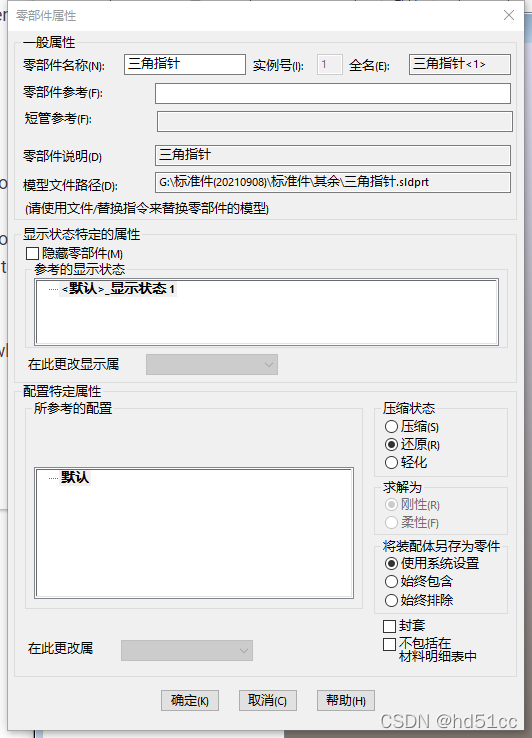
        private void SW_Clear(object sender, RoutedEventArgs e)
        {
            ModelDoc2 model = ((ModelDoc2)(sld4Handler.SwApp.ActiveDoc));
            AssemblyDoc assemblyDoc = model as AssemblyDoc;
            int errors=0;
            int warnings=0;
            ModelDoc2 swModel = (ModelDoc2)sld4Handler.SwApp.OpenDoc6(@"G:\标准件(20210908)\标准件\其余\三角指针.sldprt", (int)swDocumentTypes_e.swDocPART, (int)swOpenDocOptions_e.swOpenDocOptions_Silent, "", ref errors, ref warnings);
            assemblyDoc.AddComponent5(@"三角指针.sldprt", (int)swAddComponentConfigOptions_e.swAddComponentConfigOptions_CurrentSelectedConfig,"",true, "默认",0,0,0);
        }
System.object AddComponents3( System.object Names,System.object Transforms,System.object CoordinateSystemNames)
This example shows how to add multiple components to an assembly.

//---------------------------------------------------------------------------
// Preconditions:
// 1. Create a new part document.
//    a. Extrude a rectangular block and cut-extrude a diagonal section
//       off one face of the block.
//    b. Click Insert > Reference Geometry > Coordinate System.
//    c. Select a corner of the block for the origin of
//       the new coordinate system.
//    d. Select an edge for the Z axis of the coordinate system.
//    e. Click the green check mark to save the coordinate system.
//        Coordinate System1 appears in the FeatureManager design tree.
//    f. Save and minimize the part.
// 2. Replace part_path in the code with the full path name
//    of the new part.
// 3. Create a new assembly document.
//    a. Create a line segment sketch originating at some distance
//       from the default origin of the assembly document.
//    b. Click Insert > Reference Geometry > Coordinate System.
//    c. Select one end point of the line segment for the origin of
//       the new coordinate system.
//    d. Select the line segment for the X axis of the coordinate system.
//    e. Click the green check mark to save the coordinate system.
//       Coordinate System1 appears in the FeatureManager design tree.
//    f. Right-click on Coordinate System1 in the FeatureManager design tree,
//       select Feature Properties, and rename the coordinate system
//       and its description to differ from Coordinate System1.
//    g. Save the assembly and keep it open.
// 4. Change the namespace to match your project's name.
//
// Postconditions:
// Component part is inserted into the assembly such that
// the part's Coordinate System1 is coincident (no translation or rotation)
// with the assembly's default (not user-defined) coordinate system.
//
//----------------------------------------------------------------------------
using SolidWorks.Interop.sldworks;
using SolidWorks.Interop.swconst;
using System;
namespace AddComponents3_CSharp.csproj
{
    partial class SolidWorksMacro
    {

        AssemblyDoc assemb;
        string[] compNames = new string[1];
        double[] compXforms = new double[16];
        string[] compCoordSysNames = new string[1];
        object vcompNames;
        object vcompXforms;
        object vcompCoordSysNames;
        object vcomponents;

        public void Main()
        {
            assemb = (AssemblyDoc)swApp.ActiveDoc;

            if (((assemb != null)))
            {
                compNames[0] = "part_path";

                // Define the transformation matrix. See the IMathTransform API documentation.

                // Add a rotational diagonal unit matrix (zero rotation) to the transform
                // x-axis components of rotation
                compXforms[0] = 1.0;
                compXforms[1] = 0.0;
                compXforms[2] = 0.0;
                // y-axis components of rotation
                compXforms[3] = 0.0;
                compXforms[4] = 1.0;
                compXforms[5] = 0.0;
                // z-axis components of rotation
                compXforms[6] = 0.0;
                compXforms[7] = 0.0;
                compXforms[8] = 1.0;

                // Add a translation vector to the transform (zero translation)
                compXforms[9] = 0.0;
                compXforms[10] = 0.0;
                compXforms[11] = 0.0;

                // Add a scaling factor to the transform
                compXforms[12] = 0.0;

                // The last three elements in the transformation matrix are unused

                // Register the coordinate system name for the component
                compCoordSysNames[0] = "Coordinate System1";

                // Add the components to the assembly.
                vcompNames = compNames;
                vcompXforms = compXforms;
                //vcompXforms = Nothing   //also achieves zero rotation and translation of the component
                vcompCoordSysNames = compCoordSysNames;

                vcomponents = assemb.AddComponents3((vcompNames), (vcompXforms), (vcompCoordSysNames));

            }
        }

        public SldWorks swApp;

    }
}
Mate2 AddConcentricMateWithTolerance( System.int AlignFromEnum,System.int ConcentricPositionType,System.bool ConcentricToleranceCheck,System.double ConcentricToleranceValue,out System.int ErrorStatus)
This example shows how to add and edit a misaligned symmetric concentric mate between components.

//-----------------------------------------------------------------
// Preconditions:
// 1. Verify that the parts to open and assembly template exist.
// 2. Open a new session of SOLIDWORKS to ensure that the assembly
//    document's title is Assem1.
// 3. Open the Immediate window.
//
// Postconditions:
// 1. Opens wheel_hub.sldprt.
// 2. Opens a new assembly document titled Assem1 and adds
//    wheel_hub.sldprt as a component.
// 3. Opens and adds beam with holes.sldprt as another component.
// 4. Adds a concentric mate between the components.
// 5. Adds a misaligned symmetric concentric mate
//    between the components.
// 6. Edits the misaligned symmetric concentric mate.
// 7. Examine the Immediate window, graphics area, and the mates
//    in the Mates folder in the FeatureManager design tree.
//
// NOTE: Because the parts are used elsewhere, do not save changes.
//-----------------------------------------------------------------
using SolidWorks.Interop.sldworks;
using SolidWorks.Interop.swconst;
using System.Runtime.InteropServices;
using System;
using System.Diagnostics;

namespace Macro1CSharp.csproj
{
    public partial class SolidWorksMacro
    {

        public void Main()
        {
            ModelDoc2 swModel = default(ModelDoc2);
            AssemblyDoc swAssembly = default(AssemblyDoc);
            Component2 swInsertedComponent = default(Component2);
            MathUtility swMathUtil = default(MathUtility);
            MathTransform swTransform = default(MathTransform);
            ModelDocExtension swModelDocExt = default(ModelDocExtension);
            Mate2 swMate = default(Mate2);
	    Mate2 swLinkedMate = default(Mate2);
            Component2 swComp = default(Component2);
            SelectionMgr swSelectionManager = default(SelectionMgr);
            Feature swFeature = default(Feature);
            bool status = false;
            int errors = 0;
            int warnings = 0;
            string fileName = null;
            double swSheetWidth = 0;
            double swSheetHeight = 0;
            string AssemblyTitle = null;
            double[] TransformData = new double[16];
            object TransformDataObj = null;

            //Open the part
            fileName = "C:\\Users\\Public\\Documents\\SOLIDWORKS\\SOLIDWORKS 2018\\samples\\tutorial\\api\\wheel_hub.sldprt";
            swModel = (ModelDoc2)swApp.OpenDoc6(fileName, (int)swDocumentTypes_e.swDocPART, (int)swOpenDocOptions_e.swOpenDocOptions_Silent, "", ref errors, ref warnings);
            swApp.ActivateDoc2("wheel_hub.sldprt", false, ref errors);

            //Create an assembly
            swSheetWidth = 0;
            swSheetHeight = 0;
            swAssembly = (AssemblyDoc)swApp.NewDocument("C:\\ProgramData\\SolidWorks\\SOLIDWORKS 2018\\templates\\Assembly.asmdot", 0, swSheetWidth, swSheetHeight);
            swModel = (ModelDoc2)swAssembly;
            AssemblyTitle = swModel.GetTitle();

            //Add the part to the assembly
            swInsertedComponent = (Component2)swAssembly.AddComponent5(fileName, (int)swAddComponentConfigOptions_e.swAddComponentConfigOptions_CurrentSelectedConfig, "", false, "", -0.000181145833835217, 0.000107469465717713, 2.25750183631135E-05);
            swApp.CloseDoc(fileName);
            TransformData[0] = 1;
            TransformData[1] = 0;
            TransformData[2] = 0;
            TransformData[3] = 0;
            TransformData[4] = 1;
            TransformData[5] = 0;
            TransformData[6] = 0;
            TransformData[7] = 0;
            TransformData[8] = 1;
            TransformData[9] = 0;
            TransformData[10] = 0;
            TransformData[11] = 0;
            TransformData[12] = 1;
            TransformData[13] = 0;
            TransformData[14] = 0;
            TransformData[15] = 0;
            TransformDataObj = (object)TransformData;
            swMathUtil = (MathUtility)swApp.GetMathUtility();
            swTransform = (MathTransform)swMathUtil.CreateTransform((TransformDataObj));
            status = swInsertedComponent.SetTransformAndSolve2(swTransform);

            //Open and add another part to the assembly
            fileName = "C:\\Users\\Public\\Documents\\SOLIDWORKS\\SOLIDWORKS 2018\\samples\\tutorial\\api\\beam with holes.sldprt";
            swApp.OpenDoc6(fileName, (int)swDocumentTypes_e.swDocPART, (int)swOpenDocOptions_e.swOpenDocOptions_AutoMissingConfig, "", ref errors, ref warnings);
            swModel = (ModelDoc2)swApp.ActivateDoc3(AssemblyTitle, true, 0, ref errors);
            swAssembly = (AssemblyDoc)swModel;
            swInsertedComponent = (Component2)swAssembly.AddComponent5(fileName, (int)swAddComponentConfigOptions_e.swAddComponentConfigOptions_CurrentSelectedConfig, "", false, "", -0.0543800538871437, -0.10948954091873, 0.0944189997389913);
            swApp.CloseDoc(fileName);
            TransformData[0] = 1;
            TransformData[1] = 0;
            TransformData[2] = 0;
            TransformData[3] = 0;
            TransformData[4] = 1;
            TransformData[5] = 0;
            TransformData[6] = 0;
            TransformData[7] = 0;
            TransformData[8] = 1;
            TransformData[9] = -0.179380053887144;
            TransformData[10] = -0.0894895409187302;
            TransformData[11] = 0.0744189997389913;
            TransformData[12] = 1;
            TransformData[13] = 0;
            TransformData[14] = 0;
            TransformData[15] = 0;
            TransformDataObj = (object)TransformData;
            swMathUtil = (MathUtility)swApp.GetMathUtility();
            swTransform = (MathTransform)swMathUtil.CreateTransform((TransformDataObj));

            //Add a concentric mate
            swModelDocExt = (ModelDocExtension)swModel.Extension;
            status = swModelDocExt.SelectByRay(-0.158811046822791, -0.11180606883903, 0.110029416510201, -0.400036026779312, -0.515038074910024, -0.758094294050284, 0.000877710636365774, 2, true, 1,
            0);
            status = swModelDocExt.SelectByRay(-0.0595820179927387, -0.0282041473137156, 0.0120989536100637, -0.400036026779312, -0.515038074910024, -0.758094294050284, 0.000877710636365774, 2, true, 1,
            0);
            swMate = (Mate2)swAssembly.AddMate5((int)swMateType_e.swMateCONCENTRIC, (int)swMateAlign_e.swMateAlignALIGNED, false, 0.128546596088087, 0.0254, 0.0254, 0.0254, 0.0254, 0, 0.5235987755983,
            0.5235987755983, false, false, 0, out errors);
            swModel.ClearSelection2(true);
            swModel.EditRebuild3();

            //Move a component in order to add another mate
            status = swModelDocExt.SelectByID2("beam with holes-1@Assem1", "COMPONENT", 0, 0, 0, false, 0, null, 0);
            TransformData[0] = 0.999268594246539;
            TransformData[1] = -0.0382397247969312;
            TransformData[2] = 0;
            TransformData[3] = 0.0382397247969312;
            TransformData[4] = 0.999268594246539;
            TransformData[5] = 0;
            TransformData[6] = 0;
            TransformData[7] = 0;
            TransformData[8] = 1;
            TransformData[9] = -0.0817169203602251;
            TransformData[10] = -0.00405863499514564;
            TransformData[11] = 0.158954897029145;
            TransformData[12] = 1;
            TransformData[13] = 0;
            TransformData[14] = 0;
            TransformData[15] = 0;
            TransformDataObj = (object)TransformData;
            swMathUtil = (MathUtility)swApp.GetMathUtility();
            swTransform = (MathTransform)swMathUtil.CreateTransform((TransformDataObj));
            swSelectionManager = (SelectionMgr)swModel.SelectionManager;
            swComp = (Component2)swSelectionManager.GetSelectedObjectsComponent4(1, -1);
            status = swComp.SetTransformAndSolve2(swTransform);

            //Add a misaligned symmetric concentric mate
            status = swModelDocExt.SelectByRay(-0.0362917984178921, -0.0292363280984205, 0.194521666713399, -0.400036026779312, -0.515038074910024, -0.758094294050284, 0.000877710636365774, 2, true, 1, 0);
            status = swModelDocExt.SelectByRay(0.054967212945769, -0.0278611795938559, 0.0112380964281442, -0.400036026779312, -0.515038074910024, -0.758094294050284, 0.000877710636365774, 2, true, 1, 0);
            Debug.Print("Misaligned concentric mate:");
            swMate = (Mate2)swAssembly.AddConcentricMateWithTolerance((int)swMateAlign_e.swMateAlignALIGNED, (int)swConcentricAlignmentType_e.swConcentricAlignSymmetric, false, 0, out errors);
            if (errors == 1)
            {
                Debug.Print("  Added");

            }
            else
            {
                Debug.Print("  Not added");
            }

            swModel.ClearSelection2(true);

            //Edit the misaligned symmetric concentric mate
            //and change its position from symmetric to aligned
            status = swModelDocExt.SelectByRay(0.0548392523382404, -0.0277425865184, 0.00906375356890976, -0.400036026779312, -0.515038074910024, -0.758094294050284, 0.00107347349835279, 2, false, 0, 0);
            status = swModelDocExt.SelectByRay(0.00980255664001106, -0.0292099642897483, 0.193646683964346, -0.400036026779312, -0.515038074910024, -0.758094294050284, 0.00107347349835279, 2, true, 0, 0);
            status = swModelDocExt.SelectByID2("Concentric2", "MATE", 0, 0, 0, true, 0, null, 0);
            swAssembly.EditConcentricMate((int)swMateAlign_e.swMateAlignALIGNED, (int)swConcentricAlignmentType_e.swConcentricAlignThisMate, true, 0.095, out errors);

            swModel.ClearSelection2(true);

            if (errors == 1)
            {
                Debug.Print("  Edited");
                status = swModelDocExt.SelectByID2("Concentric2", "MATE", 0, 0, 0, true, 0, null, 0);
                swFeature = (Feature)swSelectionManager.GetSelectedObject6(1, -1);
                swMate = (Mate2)swFeature.GetSpecificFeature2();

                //Get the linked concentric mate
                swLinkedMate = (Mate2)swMate.GetLinkedMate();
                //Get current misaligned deviation
                Debug.Print("    Current misalignment deviation: " + swLinkedMate.GetCurrentMisalignedDeviation());
                //Do not use document property value for misalignment deviation
                swMate.SetUseMisalignedDeviationDocumentProperty(false);
                Debug.Print("    Use document property? " + swMate.GetUseMisalignedDeviationDocumentProperty());
                //Change mate alignment type to symmetric
                swLinkedMate.SetConcentricAlignmentType((int)swConcentricAlignmentType_e.swConcentricAlignSymmetric);
                Debug.Print("    Concentric alignment type as defined in swConcentricAlignmentType_e: " + swLinkedMate.GetConcentricAlignmentType());
                //Set maximum misalignment deviation
                swMate.SetMaximumMisalignedDeviation(0.102);
                Debug.Print("    Maximum misalignment deviation: " + swMate.GetMaximumMisalignedDeviation());

            }
            else
            {
                Debug.Print("  Not edited");
            }

            swModel.ClearSelection2(true);
            swModel.EditRebuild3();
        }

        /// <summary>
        ///  The SldWorks swApp variable is pre-assigned for you.
        /// </summary>
        public SldWorks swApp;
    }
}
System.bool CompConfigProperties6
更改零部件属性
This example shows how to change a component to an envelope.

//-----------------------------------------------------------------
// Preconditions:
// 1. Verify that the specified assembly to open exists.
// 2. Open the Immediate window.
//
// Postconditions:
// 1. Opens the assembly.
// 2. Selects the shaft washer-4 component.
// 3. Gets whether the component is an envelope.
// 4. Changes the component to an envelope.
// 5. Gets whether the component is an envelope.
// 6. Examine the Immediate window and FeatureManager design tree.
//
// NOTE: Because the assembly is used elsewhere, do not save changes.
//-------------------------------------------------------------------
using SolidWorks.Interop.sldworks;
using SolidWorks.Interop.swconst;
using System.Runtime.InteropServices;
using System;
using System.Diagnostics;

namespace Macro1CSharp.csproj
{
    public partial class SolidWorksMacro
    {
        public void Main()
        {
            ModelDoc2 swModel = default(ModelDoc2);
            ModelDocExtension swModelDocExtension = default(ModelDocExtension);
            SelectionMgr swSelectionMgr = default(SelectionMgr);
            AssemblyDoc swAssembly = default(AssemblyDoc);
            Component2 swComponent = default(Component2);
            string fileName = null;
            bool status = false;
            int errors = 0;
            int warnings = 0;

            fileName = "C:\\Users\\Public\\Documents\\SOLIDWORKS\\SOLIDWORKS 2018\\samples\\tutorial\\advdrawings\\98food processor.sldasm";
            swModel = (ModelDoc2)swApp.OpenDoc6(fileName, (int)swDocumentTypes_e.swDocASSEMBLY, (int)swOpenDocOptions_e.swOpenDocOptions_Silent, "", ref errors, ref warnings);

            //Select shaft washer-4 component
            swModelDocExtension = (ModelDocExtension)swModel.Extension;
            status = swModelDocExtension.SelectByID2("shaft washer-4@98food processor", "COMPONENT", 0, 0, 0, false, 0, null, 0);
            swSelectionMgr = (SelectionMgr)swModel.SelectionManager;
            swComponent = (Component2)swSelectionMgr.GetSelectedObjectsComponent4(1, -1);

            //Get whether selected component is an envelope
            Debug.Print("Before calling IAssemblyDoc::CompConfigProperties5:");
            Debug.Print("   Is component an envelope? " + swComponent.IsEnvelope());

            //Change the selected component to an envelope
            swAssembly = (AssemblyDoc)swModel;
            status = swAssembly.CompConfigProperties6((int)swComponentSuppressionState_e.swComponentFullyResolved, (int)swComponentSolvingOption_e.swComponentRigidSolving, true, true, "Default", false, true, (int)swASMSLDPRTCompPref_e.swAlwaysInclude);

            //Get whether the selected component is an envelope
            Debug.Print("After calling IAssemblyDoc::CompConfigProperties5:");
            Debug.Print("  Is component an envelope? " + swComponent.IsEnvelope());

            swModel.EditRebuild3();

        }

        /// <summary>
        ///  The SldWorks swApp variable is pre-assigned for you.
        /// </summary>
        public SldWorks swApp;
    }
}
System.bool CopyWithMates2
随配合复制
This example shows how to:

create a new assembly.
add two components to the assembly.
create a profile center mate between the components.
copy a component with that mate.
//--------------------------------------------------------
// Preconditions:
// 1. Open a new SOLIDWORKS session.
// 2. Copy public_documents\samples\tutorial\api\block20.sldprt and
//    cylinder20.sldprt to c:\temp.
// 3. Verify that the specified assembly document template exists.
//
// Postconditions:
// 1. Opens both parts.
// 2. Creates a new assembly.
// 3. Inserts both parts into the new assembly.
// 4. Creates a profile center mate between the two components.
// 5. Copies a component and the profile center mate.
// 6. To verify steps 4 and 5:
//    * Examine the graphics area and FeatureManager design tree.
//    * Expand Mates in the FeatureManager design tree.
//---------------------------------------------------------
using SolidWorks.Interop.sldworks;
using SolidWorks.Interop.swconst;
using System.Runtime.InteropServices;
using System;

namespace Macro1CSharp.csproj
{
    public partial class SolidWorksMacro
    {
        public void Main()
        {
            PartDoc swPart1 = default(PartDoc);
            PartDoc swPart2 = default(PartDoc);
            ModelDoc2 swModel = default(ModelDoc2);
            AssemblyDoc swAssemblyDoc = default(AssemblyDoc);
            Component2 swComponent1 = default(Component2);
            Component2 swComponent2 = default(Component2);
            ModelDocExtension swModelDocExt = default(ModelDocExtension);
            Mate2 swMate = default(Mate2);
            bool status = false;
            int errors = 0;
            int warnings = 0;
            DispatchWrapper[] dispWrapperComponentArray = new DispatchWrapper[1];
            Component2[] swComponentArray = new Component2[1];
            bool[] repeatArray = new bool[1];
            DispatchWrapper[] dispWrapperMateReferencesArray = new DispatchWrapper[1];
            double[] valueArray = new double[1];
            bool[] flipAlignmentArray = new bool[1];
            bool[] flipDimensionArray = new bool[1];
            bool[] lockRotationArray = new bool[1];
            int[] orientationArray = new int[1];

            // Open parts for new assembly
            swPart1 = (PartDoc)swApp.OpenDoc6("C:\\temp\\block20.sldprt", (int)swDocumentTypes_e.swDocPART, (int)swOpenDocOptions_e.swOpenDocOptions_Silent, "", ref errors, ref warnings);
            swPart2 = (PartDoc)swApp.OpenDoc6("C:\\temp\\cylinder20.sldprt", (int)swDocumentTypes_e.swDocPART, (int)swOpenDocOptions_e.swOpenDocOptions_Silent, "", ref errors, ref warnings);

            // Open new assembly document
            swModel = (ModelDoc2)swApp.NewDocument("C:\\ProgramData\\SolidWorks\\SOLIDWORKS 2016\\templates\\Assembly.asmdot", 0, 0, 0);
            swApp.ActivateDoc2("Assem1", false, ref errors);
            swAssemblyDoc = (AssemblyDoc)swModel;

            // Add components to assembly document
            swComponent1 = (Component2)swAssemblyDoc.AddComponent5("C:\\temp\\block20.sldprt", (int)swAddComponentConfigOptions_e.swAddComponentConfigOptions_CurrentSelectedConfig, "", false, "", 0.0522792702800426, 0.0658677995643489, 0.102016044707081);
            swComponent2 = (Component2)swAssemblyDoc.AddComponent5("C:\\temp\\cylinder20.sldprt", (int)swAddComponentConfigOptions_e.swAddComponentConfigOptions_CurrentSelectedConfig, "", false, "", 0.177061497059185, -0.00151244836160913, 0.0673233033157885);
            swModel.ViewZoomtofit2();

            // Add profile center mate
            swModelDocExt = (ModelDocExtension)swModel.Extension;
            status = swModelDocExt.SelectByID2("", "FACE", 0.0631695178495306, 0.0856797995642182, 0.137370061843797, true, 1, null, 0);
            status = swModelDocExt.SelectByID2("", "FACE", 0.141204290267694, 0.031253551638315, 0.0843440006535161, true, 1, null, 0);
            swMate = (Mate2)swAssemblyDoc.AddMate5((int)swMateType_e.swMatePROFILECENTER, (int)swMateAlign_e.swMateAlignALIGNED, true, 0.0762, 0.0254, 0.0254, 0.0254, 0.0254, 0, 0.5235987755983,
            0.5235987755983, false, true, (int)swMateWidthOptions_e.swMateWidth_Centered, out errors);
            swModel.ClearSelection2(true);

            // Copy component with profile center mate
            swComponentArray[0] = swComponent2;
            dispWrapperComponentArray[0] = new DispatchWrapper(swComponentArray[0]);
            repeatArray[0] = true;
            dispWrapperMateReferencesArray[0] = new DispatchWrapper(null);
            valueArray[0] = 0.05;
            flipAlignmentArray[0] = true;
            flipDimensionArray[0] = true;
            lockRotationArray[0] = false;
            orientationArray[0] = 0;
            status = swAssemblyDoc.CopyWithMates2(dispWrapperComponentArray, repeatArray, dispWrapperMateReferencesArray, valueArray, flipAlignmentArray, flipDimensionArray, lockRotationArray, orientationArray);

        }

        /// <summary>
        ///  The SldWorks swApp variable is pre-assigned for you.
        /// </summary>
        public SldWorks swApp;
    }
}
System.bool CreateExplodedView()
This example shows how to create multiple exploded views of an assembly.

//-------------------------------------------------------------
// Preconditions: Open an assembly document.
//
// Postconditions:
// 1. Press F5 and inspect the Immediate window.
// 2. Press F5 and inspect the graphics area at all
//    subsequent System.Diagnostics.Debugger.Break() statements.
//--------------------------------------------------------------
	using Microsoft.VisualBasic;
	using System;
	using System.Collections;
	using System.Collections.Generic;
	using System.Data;
	using System.Diagnostics;
	using SolidWorks.Interop.sldworks;
	using SolidWorks.Interop.swconst;
	using System.Runtime.InteropServices;
	namespace CreateExplodedViews_CSharp.csproj
	{
	    partial class SolidWorksMacro
	    {
	        ModelDoc2 swModel;
	        AssemblyDoc swAssembly;
	        object[] vViewName;
	        string sViewName;
	        int i;
	        public void Main()
	        {
	            swModel = (ModelDoc2)swApp.ActiveDoc;
	            swAssembly = (AssemblyDoc)swModel;
	            // Create five exploded views
	            for (i = 0; i <= 4; i++)
	            {
	                swAssembly.CreateExplodedView();
	            }
	            vViewName = (object[])swAssembly.GetExplodedViewNames();
	            Debug.Print("Number of exploded views created:  " + swAssembly.GetExplodedViewCount());
	            for (i = 0; i <= vViewName.GetUpperBound(0); i++)
	            {
	                sViewName = (string)vViewName[i];
	                Debug.Print("  Exploded
	view name: " + sViewName);
	            }
	            System.Diagnostics.Debugger.Break();
	            for (i = 0; i <= vViewName.GetUpperBound(0); i++)
	            {
	                sViewName = (string)vViewName[i];
	                swAssembly.ShowExploded2(true, sViewName);
	            }
	            System.Diagnostics.Debugger.Break();
	            for (i = 0; i <= vViewName.GetUpperBound(0); i++)
	            {
	                sViewName = (string)vViewName[i];
	                swAssembly.ShowExploded2(false, sViewName);
	            }
	            System.Diagnostics.Debugger.Break();
	            swAssembly.ViewExplodeAssembly();
	            System.Diagnostics.Debugger.Break();
	            swAssembly.ViewCollapseAssembly();
	        }
	        public SldWorks swApp;
	    }
	}
System.bool DeleteSelections( System.int DeleteOptions)
This example shows how to delete the subassembly in which the selected subassembly is a component.

//------------------------------------------------------------------
// Preconditions:
// 1. Verify that the specified assembly exists.
// 2. Open the Immediate window.
//
// Postconditions:
// 1. Opens the assembly.
// 2. Selects and deletes the [Assem4^Assem3_assemSubAssems]<1>
//    subassembly and the subassembly in which it is a component.
// 3. Examine the FeatureManager design tree and Immediate
//    window.
//
// NOTE: Because the assembly is used elsewhere, do not save
// changes.
//------------------------------------------------------------------
using SolidWorks.Interop.sldworks;
using SolidWorks.Interop.swconst;
using System.Runtime.InteropServices;
using System;
using System.Diagnostics;

namespace Macro1.CSharp.csproj
{
    public partial class SolidWorksMacro
    {
        public void Main()
        {
            ModelDoc2 swModel = default(ModelDoc2);
            ModelDocExtension swModelDocExt = default(ModelDocExtension);
            AssemblyDoc swAssembly = default(AssemblyDoc);
            bool status = false;
            int errors = 0;
            int warnings = 0;
            string fileName = null;

            fileName = "C:\\Users\\Public\\Documents\\SOLIDWORKS\\SOLIDWORKS 2018\\samples\\tutorial\\api\\assemSubAssems.sldasm";
            swModel = (ModelDoc2)swApp.OpenDoc6(fileName, (int)swDocumentTypes_e.swDocASSEMBLY, (int)swOpenDocOptions_e.swOpenDocOptions_Silent, "", ref errors, ref warnings);
            swAssembly = (AssemblyDoc)swModel;
            swModelDocExt = (ModelDocExtension)swModel.Extension;
            status = swModelDocExt.SelectByID2("Assem3^assemSubAssems-1@assemSubAssems/Assem4^Assem3_assemSubAssems-1@Assem3^assemSubAssems", "COMPONENT", 0, 0, 0, false, 0, null, 0);
            status = swAssembly.DeleteSelections((int)swAssemblyDeleteOptions_e.swDelete_SubAssembly);
            Debug.Print("Selected subassembly and the subassembly in which it is a component deleted? " + status);

        }

        /// <summary>
        ///  The SldWorks swApp variable is pre-assigned for you.
        /// </summary>
        public SldWorks swApp;
    }
}
void EditDistanceMate(
System.int AlignFromEnum,
System.bool Flip,
System.double Distance,
System.double DistanceAbsUpperLimit,
System.double DistanceAbsLowerLimit,
System.int FirstArcCondition,
System.int SecondArcCondition,
out System.int ErrorStatus)
This example shows how to add and edit a cylindrical distance mate.

//----------------------------------------------------------------------------
// Preconditions:
// 1. Ensure the specified template exists.
// 2. Open public_documents\samples\tutorial\api\cylinder20.sldprt.
// 3. Open an Immediate window.
//
// Postconditions:
// 1. Creates and saves a new cylindrical part.
// 2. Adds two cylindrical entities to a new assembly.
// 3. Creates a distance mate between the cylindrical entities.
// 4. Edits the distance mate to change the distance from 0.2 to 0.3.
// 5. Inspect the Immediate window, the graphics area, and the Mates folder
//    of the FeatureManager design tree.
//
// NOTE: Because the model is used elsewhere, do not save changes.
//----------------------------------------------------------------------------

using SolidWorks.Interop.sldworks;
using System.Diagnostics;


namespace AddDistanceMate_CSharp
{
    public partial class SolidWorksMacro
    {
        public void Main()
        {
            AssemblyDoc swAssembly = default(AssemblyDoc);
            ModelDoc2 Part = default(ModelDoc2);
            string AssemblyTitle = null;
            Component2 swInsertedComponent = default(Component2);
            Feature swFeat = default(Feature);
            bool boolstatus = false;
            int longstatus = 0;
            int longwarnings = 0;
            double swSheetWidth = 0;
            double swSheetHeight = 0;
            Mate2 swMate = default(Mate2);
            ModelDoc2 tmpObj = default(ModelDoc2);
            int errors = 0;
            Entity swEnt1 = default(Entity);
            Entity swEnt2 = default(Entity);


            Part = (ModelDoc2)swApp.ActiveDoc;

            // Shell the active part
            boolstatus = Part.Extension.SelectByRay(-0.0108900020093756, 0.0655319999998483, -0.00515652172191494, -0.400036026779312, -0.515038074910024, -0.758094294050284, 0.00167637314537445, 2, false, 1,
            0);
            Part.InsertFeatureShell(0.00254, false);

            // Save the shelled part
            longstatus = Part.SaveAs3("C:\\Users\\Public\\Documents\\SOLIDWORKS\\SOLIDWORKS 2018\\samples\\tutorial\\api\\cylinder20_shell.sldprt", 0, 2);

            // Create a new assembly
            swSheetWidth = 0;
            swSheetHeight = 0;
            Part = (ModelDoc2)swApp.NewDocument("C:\\ProgramData\\SolidWorks\\SOLIDWORKS 2018\\templates\\Assembly.asmdot", 0, swSheetWidth, swSheetHeight);

            // Insert a cylinder20_shell component
            AssemblyTitle = Part.GetTitle();
            tmpObj = swApp.OpenDoc6("C:\\Users\\Public\\Documents\\SOLIDWORKS\\SOLIDWORKS 2018\\samples\\tutorial\\api\\cylinder20_shell.sldprt", 1, 32, "", longstatus, longwarnings);
            swAssembly = (AssemblyDoc)swApp.ActivateDoc3(AssemblyTitle, true, 0, longstatus);
            swInsertedComponent = swAssembly.AddComponent5("C:\\Users\\Public\\Documents\\SOLIDWORKS\\SOLIDWORKS 2018\\samples\\tutorial\\api\\cylinder20_shell.sldprt", 0, "", false, "", 0.119562469422817, -0.0102308109635487, -0.0474663286004215);
            swApp.CloseDoc("C:\\Users\\Public\\Documents\\SOLIDWORKS\\SOLIDWORKS 2018\\samples\\tutorial\\api\\cylinder20_shell.sldprt");

            // Insert another cylinder20_shell component
            tmpObj = swApp.OpenDoc6("C:\\Users\\Public\\Documents\\SOLIDWORKS\\SOLIDWORKS 2018\\samples\\tutorial\\api\\cylinder20_shell.sldprt", 1, 32, "", errors, longwarnings);
            swAssembly = (AssemblyDoc)swApp.ActivateDoc3(AssemblyTitle, true, 0, errors);
            swInsertedComponent = swAssembly.AddComponent5("C:\\Users\\Public\\Documents\\SOLIDWORKS\\SOLIDWORKS 2018\\samples\\tutorial\\api\\cylinder20_shell.sldprt", 0, "", false, "", -0.130620346986689, -0.0101738580269739, 0.084551733918488);
            swApp.CloseDoc("C:\\Users\\Public\\Documents\\SOLIDWORKS\\SOLIDWORKS 2018\\samples\\tutorial\\api\\cylinder20_shell.sldprt");

            // Select two cylindrical entities
            boolstatus = Part.Extension.SelectByRay(-0.140174514310559, 0.00237221117538411, 0.0264513806530431, -0.400036026779312, -0.515038074910024, -0.758094294050284, 0.00086563679245283, 2, false, 1,
            0);
            swEnt1 = (Entity)((SelectionMgr)(Part.SelectionManager)).GetSelectedObject6(1, -1);
            boolstatus = Part.Extension.SelectByRay(0.0679787981690652, -0.00725673614920197, -0.0758574895979791, -0.400036026779312, -0.515038074910024, -0.758094294050284, 0.000636203082166533, 2, true, 1,
            0);
            swEnt2 = (Entity)((SelectionMgr)(Part.SelectionManager)).GetSelectedObject6(1, -1);

            swEnt1.Select4(true, null);
            swEnt2.Select4(true, null);

            // Add a center-to-center distance mate between the selected cylindrical entities
            swMate = swAssembly.AddDistanceMate(2, false, 0.2, 0, 0, 1, 1, out errors);
            Debug.Print("First arc condition as defined in swDistanceMateArcConditions_e: " + swMate.DistanceFirstArcCondition);
            Debug.Print("Second arc condition as defined in swDistanceMateArcConditions_e: " + swMate.DistanceSecondArcCondition);
            swFeat = (Feature)swMate;

            Part.EditRebuild3();

            // Edit the distance mate to change the distance from 0.2 to 0.3
            boolstatus = Part.Extension.SelectByRay(-0.0936626010895907, 0.000678476678046991, -0.000454698905400619, -0.400036026779312, -0.515038074910024, -0.758094294050284, 0.000808436123348018, 2, true, 1,
            0);
            swEnt1 = (Entity)((SelectionMgr)(Part.SelectionManager)).GetSelectedObject6(1, -1);
            boolstatus = Part.Extension.SelectByRay(0.0803986691953469, -0.00107796570199525, -0.0914337018962783, -0.400036026779312, -0.515038074910024, -0.758094294050284, 0.000808436123348018, 2, true, 2,
            0);
            swEnt2 = (Entity)((SelectionMgr)(Part.SelectionManager)).GetSelectedObject6(2, -1);

            swEnt1.Select4(true, null);
            swEnt2.Select4(true, null);
            swFeat.Select2(true, 0);

            swAssembly.EditDistanceMate(2, false, 0.3, 0, 0, 1, 1, out errors);

            Part.EditRebuild3();
        }

        // The SldWorks swApp variable is pre-assigned for you.
        public SldWorks swApp;

    }
}
System.int EditPart2(
System.bool Silent,
System.bool AllowReadOnly,
ref System.int Information)
This example shows how to suppress the selected component feature.

//------------------------------------------------
// Preconditions:
// 1. Open an assembly document.
// 2. Select a component feature in the FeatureManager
//    design tree.
// 3. Open the Immediate window.
//
// Postconditions:
// 1. Suppresses the selected component feature.
// 2. Prints the names of the assembly and the suppressed
//    component feature to the Immediate window.
// 3. Examine the Immediate window.
//
// NOTE: Editing a component requires that geometry on
// the component to be selected. However, not
// all features are associated with geometry.
// Therefore, it is necessary to select the component
// before attempting to edit the component.
//------------------------------------------------

using SolidWorks.Interop.sldworks;
using SolidWorks.Interop.swconst;
using System.Runtime.InteropServices;
using System;
using System.Diagnostics;

namespace SelectFeatureCSharp.csproj
{
    public partial class SolidWorksMacro
    {


        public void Main()
        {
            ModelDoc2 swModel = default(ModelDoc2);
            AssemblyDoc swAssy = default(AssemblyDoc);
            ModelDoc2 swEditModel = default(ModelDoc2);
            PartDoc swEditPart = default(PartDoc);
            AssemblyDoc swEditAssy = default(AssemblyDoc);
            SelectionMgr swSelMgr = default(SelectionMgr);
            Feature swFeat = default(Feature);
            Component2 swComp = default(Component2);
            string featName = null;
            int status = 0;
            int info = 0;
            bool retVal = false;

            swModel = (ModelDoc2)swApp.ActiveDoc;
            swAssy = (AssemblyDoc)swModel;
            swSelMgr = (SelectionMgr)swModel.SelectionManager;
            swFeat = (Feature)swSelMgr.GetSelectedObject6(1, -1);
            Debug.Assert((swFeat != null));
            swComp = (Component2)swSelMgr.GetSelectedObjectsComponent2(1);
            Debug.Assert((swComp != null));

            Debug.Print("File = " + swModel.GetPathName());
            Debug.Print("    " + swFeat.Name + " <" + swFeat.GetTypeName() + ">");
            Debug.Print("");
            featName = swFeat.Name;
            retVal = swComp.Select2(false, 0);
            Debug.Assert(retVal);
            status = swAssy.EditPart2(true, false, ref info);
            Debug.Assert((int)swEditPartCommandStatus_e.swEditPartSuccessful == status);
            swEditModel = (ModelDoc2)swAssy.GetEditTarget();
            switch (swEditModel.GetType())
            {
                case (int)swDocumentTypes_e.swDocPART:
                    swEditPart = (PartDoc)swEditModel;
                    swFeat = (Feature)swEditPart.FeatureByName(featName);
                    Debug.Assert((swFeat != null));
                    retVal = swFeat.Select2(false, 0);
                    Debug.Assert(retVal);
                    break;
                case (int)swDocumentTypes_e.swDocASSEMBLY:
                    swEditAssy = (AssemblyDoc)swEditModel;
                    swFeat = (Feature)swEditAssy.FeatureByName(featName);
                    Debug.Assert((swFeat != null));
                    retVal = swFeat.Select2(false, 0);
                    Debug.Assert(retVal);
                    break;
                default:
                    Debug.Assert(false);
                    break;
            }
            // Suppress the selected feature
            retVal = swEditModel.EditSuppress2();
            Debug.Assert(retVal);
            swAssy.EditAssembly();


        }

        /// <summary>
        ///  The SldWorks swApp variable is pre-assigned for you.
        /// </summary>
        public SldWorks swApp;
    }
}
This example shows how to insert a cavity in a mold base.

//------------------------------------------------------------------------------------
// Preconditions:
// 1. Create a new folder and copy public_documents\samples\tutorial\molds\telephone.sldprt
//    to that folder.
// 2. Click File > New > Part > OK to create a new part document.
//    a. Insert a sketch of a rectangle with a length of 240 mm and width of 350 mm.
//    b. Using the sketch, create a boss extrude feature with a depth of 160 mm.
//    c. Save the part as telephoneMoldBase.sldprt in the folder created in step 1.
// 3. Click File > New > Assembly > OK to create a new assembly document.
//    a. Click telephoneMoldBase in Part/Assembly to Insert in the PropertyManager page.
//    b. Click OK.
//    c. Click Insert Components on the Assembly toolbar, click Browse in
//       Part/Assembly to Insert, click telephone.sldprt located in the folder
//       created in step 1, and click Open.
//    d. Drop telephone.sldprt in the graphics area.
//    e. Click View > Display > Hidden Lines Visible.
//    f. In the FeatureManager design tree, click telephone<1> and click Move Component
//       in the Assembly toolbar.
//    g. Move telephone<1> into the center of telephoneMoldBase<1> and click OK.
//       TIP: Change the view orientation to Top and Front to help center telephone<1>.
//    h. Click File > Save All > Rebuild and save the document (recommended),
//       navigate to the folder created in step 1, type AssemInterim.sldasm in
//       File name, and click Save.
// 4. Click telephoneMoldBase<1> in the FeatureManager design tree.
// 5. Ctrl+click telephone<1> in the FeatureManager design tree.
//
// Postconditions:
// 1. Creates Cavity1 in telphoneMoldBase<1>.
// 2. Expand telephoneMoldBase<1> to verify step 1.
//-----------------------------------------------------------------------------------
using SolidWorks.Interop.sldworks;
using SolidWorks.Interop.swconst;
using System.Runtime.InteropServices;
using System;

namespace Macro1CSharp.csproj
{
    public partial class SolidWorksMacro
    {

        public void Main()
        {
            ModelDoc2 swModel = default(ModelDoc2);
            SelectionMgr swSelMgr = default(SelectionMgr);
            AssemblyDoc swAssy = default(AssemblyDoc);
            Component2 swMoldBaseComp = default(Component2);
            Component2 swCoreComp1 = default(Component2);
            int nRetval = 0;
            int nInfo = 0;
            bool bRet = false;

            swModel = (ModelDoc2)swApp.ActiveDoc;
            swAssy = (AssemblyDoc)swModel;

            swSelMgr = (SelectionMgr)swModel.SelectionManager;
            swMoldBaseComp = (Component2)swSelMgr.GetSelectedObjectsComponent2(1);
            swCoreComp1 = (Component2)swSelMgr.GetSelectedObjectsComponent2(2);

            swModel.ClearSelection2(true);

            bRet = swMoldBaseComp.Select2(false, 0);
            nRetval = swAssy.EditPart2(true, true, ref nInfo);
            bRet = swCoreComp1.Select2(true, 0);
            swAssy.InsertCavity4(0.0, 0, 0.0, true, (int)swCavityScaleType_e.swAboutCentroid, 0);
            swAssy.EditAssembly();

        }

        /// <summary>
        ///  The SldWorks swApp variable is pre-assigned for you.
        /// </summary>
        public SldWorks swApp;
    }
}
System.object FeatureByName(
System.string Name)
This example shows how to step through the FeatureManager design tree of a model by rolling back to each feature in reverse sequence. Running an example like this can provide insight into the design intent of the user.

//-----------------------------------
// Preconditions:
// 1. Open a part or assembly document.
// 2. Open the Immediate window.
//
// Postconditions:
// 1. Observe the FeatureManager design tree
//    while the macro executes.
// 2. Examine the Immediate window to see the
//    names of the features rolled back and forward.
//
// NOTE: The delay between steps is set to 1 second.
//-----------------------------------
using SolidWorks.Interop.sldworks;
using SolidWorks.Interop.swconst;
using System.Runtime.InteropServices;
using System;
using System.Diagnostics;
using System.Collections;


namespace EditRollbackCSharp.csproj
{
    public partial class SolidWorksMacro
    {


        public void Main()
        {
            ModelDoc2 swModel = default(ModelDoc2);
            ModelView swModelView = default(ModelView);
            PartDoc swPart = default(PartDoc);
            AssemblyDoc swAssy = default(AssemblyDoc);
            FeatureManager swFeatMgr = default(FeatureManager);
            Feature swFeat = default(Feature);
            object[] featFace = null;
            Face2 swFace = default(Face2);
            object rect = null;
            string featureName = null;
            ArrayList featName = new ArrayList();
            string nameString;
            int docType = 0;
            int i = 0;
            int j = 0;
            bool status = false;

            swModel = (ModelDoc2)swApp.ActiveDoc;
            swModelView = (ModelView)swModel.ActiveView;
            rect = null;
            swFeatMgr = (FeatureManager)swModel.FeatureManager;

            swFeat = (Feature)swModel.FirstFeature();
            docType = swModel.GetType();
            switch (docType)
            {
                case (int)swDocumentTypes_e.swDocPART:
                    swPart = (PartDoc)swModel;
                    break;
                case (int)swDocumentTypes_e.swDocASSEMBLY:
                    swAssy = (AssemblyDoc)swModel;
                    break;
                default:
                    Debug.Print("Open a part or assembly document, then rerun this macro.");
                    break;
            }


            while ((swFeat != null))
            {
                featureName = swFeat.Name;
                featName.Add(featureName);
                swFeat = (Feature)swFeat.GetNextFeature();
            }

            // Playback each feature in the FeatureManager design tree
            for (i = 0; i <= ((featName.Count) - 1); i++)
            {
                nameString = (string)featName[i];
                Debug.Print(nameString);
                status = swFeatMgr.EditRollback((int)swMoveRollbackBarTo_e.swMoveRollbackBarToAfterFeature, nameString);
                // Do not assert because you may be trying to roll back or roll forward
                // to a feature that cannot be rolled back or forward to; for example,
                // the Lighting or Annotations folder
                //Debug.Assert status

                // Remove any previous highlights
                swModelView.GraphicsRedraw(rect);
                // Highlight feature if it has any geometry
                switch (docType)
                {
                    case (int)swDocumentTypes_e.swDocPART:
                        swPart = (PartDoc)swModel;
                        swFeat = (Feature)swPart.FeatureByName(nameString);
                        break;
                    case (int)swDocumentTypes_e.swDocASSEMBLY:
                        swAssy = (AssemblyDoc)swModel;
                        swFeat = (Feature)swAssy.FeatureByName(nameString);
                        break;
                }

                featFace = (object[])swFeat.GetFaces();
                if (featFace != null)
                {
                    for (j = 0; j <= ((featFace.GetUpperBound(0))); j++)
                    {
                        swFace = (Face2)featFace[j];
                        swFace.Highlight(true);
                    }
                }

                // Only pause if rollback is successful
                if (status)
                {
                    // Pause for 1 second
                    System.Threading.Thread.Sleep(1000);
                    // Allow SOLIDWORKS to refresh screen
                    System.Windows.Forms.Application.DoEvents();
                }
            }
            // Remove highlight from last feature
            swModelView.GraphicsRedraw(rect);

        }

        /// <summary>
        ///  The SldWorks swApp variable is pre-assigned for you.
        /// </summary>
        public SldWorks swApp;
    }
}
This example shows how to move selected assembly components to a newly created folder in the FeatureManager design tree.

//---------------------------------------------------------------------------
// Preconditions:
// 1. Verify that the specified assembly to open exists.
// 2. Open an Immediate window.
//
// Postconditions:
// 1. Opens the specified assembly document.
// 2. Selects the valve<1> and valve_guide<1> components.
// 3. Creates a folder named Folder1 in the FeatureManager design tree.
// 4. Moves the valve<1> and valve_guide<1> components to Folder1,
//    which you can verify by expanding Folder1.
// 5. Examine the Immediate window.
//
// NOTE: Because the assembly document is used by elsewhere,
// do not save any changes.
//---------------------------------------------------------------------------

using Microsoft.VisualBasic;
using System;
using System.Collections;
using System.Collections.Generic;
using System.Data;
using System.Diagnostics;
using SolidWorks.Interop.sldworks;
using SolidWorks.Interop.swconst;
using System.Runtime.InteropServices;
namespace FeatureFolderLocation_CSharp.csproj
{
    partial class SolidWorksMacro
    {
        ModelDoc2 modelDoc2;
        AssemblyDoc assemblyDoc;
        FeatureManager featureMgr;
        ModelDocExtension modelDocExt;
        SelectionMgr selectionMgr;
        Feature feature;
        object selObj;
        Feature feat;
        Feature folderFeat;
        int errors;
        int warnings;
        int count;
        Component2 componentToMove;
        object[] componentsToMove;
        int i;
        bool retVal;

        public void Main()
        {
            //Open assembly document
            swApp.OpenDoc6("C:\\Users\\Public\\Documents\\SOLIDWORKS\\SOLIDWORKS 2018\\samples\\tutorial\\motionstudies\\valve_cam.sldasm", (int)swDocumentTypes_e.swDocASSEMBLY, (int)swOpenDocOptions_e.swOpenDocOptions_Silent, "", ref errors, ref warnings);
            modelDoc2 = (ModelDoc2)swApp.ActiveDoc;
            assemblyDoc = (AssemblyDoc)modelDoc2;

            //Select and get the two valve-related components to move to the new folder
            modelDocExt = modelDoc2.Extension;
            selectionMgr = (SelectionMgr)modelDoc2.SelectionManager;
            modelDocExt.SelectByID2("valve-1@valve_cam", "COMPONENT", 0, 0, 0, true, 0, null, 0);
            selObj = selectionMgr.GetSelectedObject6(1, -1);
            modelDocExt.SelectByID2("valve_guide-1@valve_cam", "COMPONENT", 0, 0, 0, true, 0, null, 0);
            selectionMgr.GetSelectedObject6(2, -1);
            count = selectionMgr.GetSelectedObjectCount2(0);
            componentsToMove = new object[count];
            for (i = 0; i <= count - 1; i++)
            {
                componentToMove = (Component2)selectionMgr.GetSelectedObjectsComponent4(i + 1, 0);
                componentsToMove[i] = componentToMove;
            }

            //Create the folder where to move the selected components
            featureMgr = modelDoc2.FeatureManager;
            feature = featureMgr.InsertFeatureTreeFolder2((int)swFeatureTreeFolderType_e.swFeatureTreeFolder_EmptyBefore);
            feature = (Feature)assemblyDoc.FeatureByName("Folder1");

            //Move the selected components to the new folder
            retVal = assemblyDoc.ReorderComponents(componentsToMove, feature, (int)swReorderComponentsWhere_e.swReorderComponents_LastInFolder);

            modelDocExt.SelectByID2("valve-1@valve_cam", "COMPONENT", 0, 0, 0, true, 0, null, 0);
            feat = (Feature)selectionMgr.GetSelectedObject6(1, -1);

            featureMgr = modelDoc2.FeatureManager;
            folderFeat = featureMgr.FeatureFolderLocation(feat);

            Debug.Print("Component valve-1@valve_cam folder feature: " + folderFeat.Name);

        }

        public SldWorks swApp;

    }

}
System.object GetActiveGroundPlane(
System.int Config_opt,
System.object Config_names)
This example shows how to insert and activate a ground plane in the current configuration of an assembly.

'----------------------------------------------------------------------------
' Preconditions: Open public_documents\introsw\vanity_assembly.sldasm.
'
' Postconditions:
' 1. Inserts Ground Plane1 in the Ground Planes folder.
' 2. Inspect the FeatureManager design tree.
'
' NOTE: Because the model is used elsewhere, do not save changes.
'----------------------------------------------------------------------------
Dim swApp As SldWorks.SldWorks
Dim Part As SldWorks.ModelDoc2
Dim featMgr As SldWorks.FeatureManager
Dim feat As SldWorks.Feature
Dim groundPlanes As Variant
Dim boolstatus As Boolean

Option Explicit
Sub main()

    Set swApp = Application.SldWorks
    Set Part = swApp.ActiveDoc
    Set featMgr = Part.FeatureManager


    boolstatus = Part.Extension.SelectByRay(-9.07572786993001E-02, -3.35232970080597E-02, -0.329520078481409, -0.560777860996441, 0.738723196597798, -0.373920084275486, 1.28607075733318E-02, 2, False, 0, 0)
    Set feat = featMgr.InsertGroundPlane(False)


    boolstatus = Part.Extension.SelectByID2("Ground Plane1", "MAGNETICGROUNDPLANE", 0, 0, 0, False, 0, Nothing, 0)
    boolstatus = Part.ActivateGroundPlane(swThisConfiguration, Null)

    groundPlanes = Part.GetActiveGroundPlane(swAllConfiguration, Null)


End Sub
System.object GetComponentByID( System.int ID)
This example shows how to get the top-level components in an assembly using their component IDs.

//--------------------------------------------------------------------------
// Preconditions:
// 1. Open an assembly document containing subassemblies.
// 2. Open the Immediate window.
//
// Postconditions:
// 1. Traverses the assembly.
// 2. Gets the name and component ID of each top-level component
//    in the assembly.
// 3. Adds each component ID to an array and traverses the array.
//    a. Gets each top-level component using its component ID.
//    b. Gets the name and component ID of each top-level component
//       in the assembly.
// 4. Examine the Immediate window and FeatureManager design tree.
//---------------------------------------------------------------------------
using SolidWorks.Interop.sldworks;
using SolidWorks.Interop.swconst;
using System.Runtime.InteropServices;
using System;
using System.Diagnostics;

namespace Macro1CSharp.csproj
{
    public partial class SolidWorksMacro
    {

        public void Main()
        {
            ModelDoc2 swModel = default(ModelDoc2);
            AssemblyDoc swAssemblyDoc = default(AssemblyDoc);
            ConfigurationManager swConfMgr = default(ConfigurationManager);
            Configuration swConf = default(Configuration);
            Component2 swRootComp = default(Component2);
            object[] vChildComp = null;
            Component2 swChildComp = default(Component2);
            int i = 0;
            int compID = 0;
            int[] compIDs = null;
            int nbrComp = 0;

            swModel = (ModelDoc2)swApp.ActiveDoc;
            swAssemblyDoc = (AssemblyDoc)swModel;
            swConfMgr = (ConfigurationManager)swModel.ConfigurationManager;
            swConf = (Configuration)swConfMgr.ActiveConfiguration;
            swRootComp = (Component2)swConf.GetRootComponent3(true);

            Debug.Print("Get top-level components by traversing assembly:");
            vChildComp = (object[])swRootComp.GetChildren();
            nbrComp = vChildComp.Length;
            compIDs = new int[nbrComp + 1];
            for (i = 0; i < nbrComp; i++)
            {
                swChildComp = (Component2)vChildComp[i];
                compID = swChildComp.GetID();
                Debug.Print("  Component name: " + swChildComp.Name2 + ", Component ID: " + compID);
                // Add component ID to an array
                compIDs[i] = compID;
            }

            Debug.Print("");

            Debug.Print("Get top-level components using component IDs:");
            swChildComp = null;
            for (i = 0; i < compIDs.Length - 1; i++)
            {
                compID = compIDs[i];
                swChildComp = (Component2)swAssemblyDoc.GetComponentByID(compID);
                Debug.Print("  Component name: " + swChildComp.Name2 + ", Component ID: " + swChildComp.GetID());
            }

        }

        /// <summary>
        ///  The SldWorks swApp variable is pre-assigned for you.
        /// </summary>
        public SldWorks swApp;
    }
}
Component2 GetComponentByName( System.string CompName)
This examples shows how to get a component by name and to determine if that component is fixed or floating.

//-------------------------------------------
// Preconditions:
// 1. Open public_documents\samples\tutorial\EDraw\claw\claw-mechanism.sldasm.
// 2. Open the Immediate window.
//
// Postconditions:
// 1. Gets the specified component.
// 2. Gets whether the specified component is fixed.
// 3. Examine the Immediate window.
//-------------------------------------------
using SolidWorks.Interop.sldworks;
using SolidWorks.Interop.swconst;
using System;
using System.Diagnostics;
using System.Runtime.InteropServices;
namespace Macro1.csproj
{
    public partial class SolidWorksMacro
    {
        ModelDoc2 swModel;
        AssemblyDoc swAssy;
        Component2 swComp;
        public void Main()
        {
            swModel = swApp.ActiveDoc as ModelDoc2;
            swAssy = swModel as AssemblyDoc;
            string compName;
            compName = "center-1";
            swComp = swAssy.GetComponentByName(compName);
            bool bRet;
            bRet = swComp.IsFixed();
            Debug.Print("Is component fixed: " + bRet);
        }
        /// <summary>
        ///  The SldWorks swApp variable is pre-assigned for you.
        /// </summary>
        public SldWorks swApp;
    }
}
System.object GetComponents(System.bool ToplevelOnly)
This example shows how to get all of the mates (IMate2 and IMateInPlace objects) for all components in an assembly.

//----------------------------------------
// Preconditions:
// 1. Open public_documents\samples\tutorial\advdrawings\bladed shaft.sldasm.
// 2. Open the Immediate window.
//
// Postconditions:
// 1. Gets the components and mates.
// 2. Examine the Immediate window.
//-----------------------------------------
using SolidWorks.Interop.sldworks;
using SolidWorks.Interop.swconst;
using System;
using System.Diagnostics;
namespace GetMatesComponent_CSharp.csproj
{
    partial class SolidWorksMacro
    {
        public void Main()
        {
            ModelDoc2 swModel;
            Component2 swComponent;
            AssemblyDoc swAssembly;
            object[] Components = null;
            object[] Mates = null;
            Mate2 swMate;
            MateInPlace swMateInPlace;
            int numMateEntities = 0;
            int typeOfMate = 0;
            int i = 0;

            swModel = (ModelDoc2)swApp.ActiveDoc;
            swAssembly = (AssemblyDoc)swModel;
            Components = (Object[])swAssembly.GetComponents(false);
            foreach (Object SingleComponent in Components)
            {
                swComponent = (Component2)SingleComponent;
                Debug.Print("Name of component: " + swComponent.Name2);
                Mates = (Object[])swComponent.GetMates();
                if ((Mates != null))
                {
                    foreach (Object SingleMate in Mates)
                    {
                        if (SingleMate is SolidWorks.Interop.sldworks.Mate2)
                        {
                            swMate = (Mate2)SingleMate;
                            typeOfMate = swMate.Type;
                            switch (typeOfMate)
                            {
                                case 0:
                                    Debug.Print(" Mate type: Coincident");
                                    break;
                                case 1:
                                    Debug.Print(" Mate type: Concentric");
                                    break;
                                case 2:
                                    Debug.Print(" Mate type: Perpendicular");
                                    break;
                                case 3:
                                    Debug.Print(" Mate type: Parallel");
                                    break;
                                case 4:
                                    Debug.Print(" Mate type: Tangent");
                                    break;
                                case 5:
                                    Debug.Print(" Mate type: Distance");
                                    break;
                                case 6:
                                    Debug.Print(" Mate type: Angle");
                                    break;
                                case 7:
                                    Debug.Print(" Mate type: Unknown");
                                    break;
                                case 8:
                                    Debug.Print(" Mate type: Symmetric");
                                    break;
                                case 9:
                                    Debug.Print(" Mate type: CAM follower");
                                    break;
                                case 10:
                                    Debug.Print(" Mate type: Gear");
                                    break;
                                case 11:
                                    Debug.Print(" Mate type: Width");
                                    break;
                                case 12:
                                    Debug.Print(" Mate type: Lock to sketch");
                                    break;
                                case 13:
                                    Debug.Print(" Mate type: Rack pinion");
                                    break;
                                case 14:
                                    Debug.Print(" Mate type: Max mates");
                                    break;
                                case 15:
                                    Debug.Print(" Mate type: Path");
                                    break;
                                case 16:
                                    Debug.Print(" Mate type: Lock");
                                    break;
                                case 17:
                                    Debug.Print(" Mate type: Screw");
                                    break;
                                case 18:
                                    Debug.Print(" Mate type: Linear coupler");
                                    break;
                                case 19:
                                    Debug.Print(" Mate type: Universal joint");
                                    break;
                                case 20:
                                    Debug.Print(" Mate type: Coordinate");
                                    break;
                                case 21:
                                    Debug.Print(" Mate type: Slot");
                                    break;
                                case 22:
                                    Debug.Print(" Mate type: Hinge");
                                    //
                                    break;
                                // Add new mate types introduced after SOLIDWORKS 2010 FCS here
                            }
                        }
                        if (SingleMate is SolidWorks.Interop.sldworks.MateInPlace)
                        {
                            swMateInPlace = (MateInPlace)SingleMate;
                            numMateEntities = swMateInPlace.GetMateEntityCount();
                            for (i = 0; i <= numMateEntities - 1; i++)
                            {
                                Debug.Print(" Mate component name: " + swMateInPlace.get_MateComponentName(i));
                                Debug.Print(" Type of Inplace mate entity: " + swMateInPlace.get_MateEntityType(i));
                            }
                            Debug.Print("");
                        }
                    }
                }
                Debug.Print("");
            }
        }
        public SldWorks swApp;
    }
}
This example shows how to open an assembly in Large Design Review mode.

//----------------------------------------------------------------------------
// Preconditions:
// 1. Verify that the specified assembly to open in Large Design Review mode exists.
// 2. Open the Immediate window.
//
// Postconditions:
// 1. Click OK in the Large Design Review dialog.
// 2. Opens the assembly.
// 3. Creates a section view.
// 4. Creates four snapshots in the DisplayManager:
//    * Home
//    * ASnap
//    * Snap2
//    * Snap3
// 5. Click OK in the Name Snapshot dialog.
// 6. Selects and fully resolves a component.
// 7. Inspect the Immediate window for snapshot information and inspect
//    the graphics area.
//
// NOTE: Because the assembly is used elsewhere, do not save changes.
// ---------------------------------------------------------------------------
using Microsoft.VisualBasic;
using System;
using System.Collections;
using System.Collections.Generic;
using System.Data;
using System.Diagnostics;
using SolidWorks.Interop.sldworks;
using SolidWorks.Interop.swconst;
using System.Runtime.InteropServices;

namespace Macro1CSharp.csproj
{
    partial class SolidWorksMacro
    {
        AssemblyDoc Part;
        ModelDoc2 Model;
        SnapShot snap;
        object[] snaps;
        SnapShot snap1;
        SnapShot snap2;
        SnapShot snap3;
        int i;
        bool boolstatus;
        int longstatus;
        int longwarnings;

        public void Main()
        {
            string large_assembly_document;
            large_assembly_document = "C:\\Users\\Public\\Documents\\SOLIDWORKS\\SOLIDWORKS 2018\\samples\\tutorial\\advdrawings\\motor casing.sldasm";
            Part = (AssemblyDoc)swApp.OpenDoc6(large_assembly_document, (int)swDocumentTypes_e.swDocASSEMBLY, (int)swOpenDocOptions_e.swOpenDocOptions_ViewOnly, "", ref longstatus, ref longwarnings);
            Model = (ModelDoc2)Part;

            // Create section view
            SectionViewData sViewData = default(SectionViewData);
            sViewData = Model.ModelViewManager.CreateSectionViewData();
            sViewData.FirstPlane = null;
            sViewData.FirstReverseDirection = false;
            sViewData.FirstOffset = -0.00508;
            sViewData.FirstRotationX = 0;
            sViewData.FirstRotationY = 0;
            sViewData.FirstColor = 16711680;
            sViewData.ShowSectionCap = true;
            sViewData.KeepCapColor = true;

            ModelViewManager mvmgr = default(ModelViewManager);
            mvmgr = Model.ModelViewManager;
            boolstatus = mvmgr.CreateSectionView(sViewData);
            Model.ClearSelection2(true);
            Model.ShowNamedView2("*Front", 1);
            Model.ShowNamedView2("*Dimetric", 9);

            // Add a named snapshot
            snap1 = mvmgr.AddSnapShot("ASnap");
            // Open dialog box to name the next snapshot
            snap2 = mvmgr.AddSnapShot("?");
            // Add a snapshot with the next default name
            snap3 = mvmgr.AddSnapShot("");

            snap1.Comment = "<TS> This is a comment for ASnap.";

            snaps = (object[])mvmgr.GetSnapShots();

            for (i = 0; i <= snaps.GetUpperBound(0); i++)
            {
                snap = (SnapShot)snaps[i];
                snap.Activate();
                Debug.Print("Snapshot name: " + snap.Name);
                Debug.Print("      Comment: " + snap.Comment);
                Debug.Print("       ViewID: " + snap.ViewId);
            }


            // Selects a component
            boolstatus = Model.Extension.SelectByID2("motor casing-1@motor casing", "COMPONENT", 0, 0, 0, false, 0, null, 0);

            // Fully resolve only the selected components
            Part.SelectiveOpen(true, false);

        }

        public SldWorks swApp;

    }
}
Component2 GetEditTargetComponent()
This example shows how to reorder components in an assembly.

'----------------------------------------------------------------------------
' Preconditions:
' 1. Copy and paste this code in the main module.
' 2. Click Insert > Class module and copy and paste this code in that module.
' 3. Open public_documents\samples\tutorial\assemblyvisualize\food_processor.sldasm.
' 4. Open the Immediate window.
'
' Postconditions:
' 1. Run the macro.
' 2. Interactively select both shaft washer components in the FeatureManager design tree.
' 3. Press F5.
' 4. Interactively select the blade shaft subassembly in the FeatureManager design tree.
' 5. Press F5.
' 6. Expand and examine the blade shaft subassembly in the FeatureManager design tree to verify
'    that both shaft washer components moved to the subassembly.
' 7. Examine the Immediate window.
'
' NOTE: Because the assembly is used elsewhere, do not save changes.
' ----------------------------------------------------------------------------

'Module
Option Explicit
Dim myClass As Class1
Sub main()
    Dim swApp As SldWorks.SldWorks
    Dim myModel As SldWorks.ModelDoc2
    Dim myAssem As SldWorks.AssemblyDoc
    Dim selMgr As SldWorks.SelectionMgr
    Dim selCount As Long, selType As Long
    Dim selObj As Object
    Dim selSource() As SldWorks.Component2
    Dim vSource As Variant
    Dim selTarget As SldWorks.Component2
    Dim boolstatus As Boolean
    Set swApp = Application.SldWorks
    Set myModel = swApp.ActiveDoc
    Set myAssem = myModel
    Set myClass = New Class1
    Set myClass.msrcAssemblyDoc = myAssem
    ' Interactively select components to move
    ' The selected components must be from the
    ' same level of an assembly
    ' Press F5
    Stop
    Set selMgr = myModel.SelectionManager
    selCount = selMgr.GetSelectedObjectCount2(0)
    If (selCount = 0) Then
        Exit Sub
    End If
    ReDim selSource(0 To selCount - 1)
    Dim i As Long
    For i = 1 To selCount
        selType = selMgr.GetSelectedObjectType3(i, 0)
        If (selType = SwConst.swSelCOMPONENTS) Then
            Set selObj = selMgr.GetSelectedObject6(i, 0)
            Set selSource(i - 1) = selObj
        End If
    Next i
    vSource = selSource
    myModel.ClearSelection2 True
    ' Interactively select a top-level assembly or
    ' sub-assembly where to move the
    ' previously selected components
    ' Press F5
    Stop
    selCount = selMgr.GetSelectedObjectCount2(0)
    If (selCount > 0) Then
        selType = selMgr.GetSelectedObjectType3(1, 0)
        If selType = SwConst.swSelCOMPONENTS Then
            Set selObj = selMgr.GetSelectedObject6(1, 0)
            If Not selObj Is Nothing Then
                Set selTarget = selObj
            Else
                Set selTarget = myAssem.GetEditTargetComponent
            End If
        End If
    End If
    myModel.ClearSelection2 True
    If Not (selTarget Is Nothing) Then
        boolstatus = myAssem.ReorganizeComponents((vSource), selTarget)
        ' AssemblyDoc ComponentReorganizeNotify event is fired
        If boolstatus = False Then
            Debug.Print "Reordering components failed."
        Else
            Debug.Print "Reordering components succeeded."
        End If
    End If
End Sub
Back to top

'Class1
Option Explicit

Public WithEvents msrcAssemblyDoc   As SldWorks.AssemblyDoc
Public Function msrcAssemblyDoc_ComponentReorganizeNotify(ByVal sourceName As String, ByVal targetName As String) As Long
    Debug.Print "IAssemblyDocEvent ComponentReorganizeNotify"
    Debug.Print "  Source component is: " & sourceName
    Debug.Print "  Target component is: " & targetName
    msrcAssemblyDoc_ComponentReorganizeNotify = 1
End Function
System.string GetExplodedViewConfigurationName( System.string ExplodedViewName)
This example shows how to get:

number of exploded views for a configuration.
name of each exploded view for a configuration.
name of the configuration for each exploded view.
name of the exploded view shown in the model.
//----------------------------------------------------------------------------
// Preconditions:
// 1. Open public_documents\samples\tutorial\pdmworks\speaker.sldasm.
// 2. Open the Immediate window.
//
// Postconditions:
// 1. Gets the name of the active configuration.
// 2. Creates five exploded views for the active configuration.
// 3. Gets the number of exploded views for the active configuration.
// 4. Gets the name of:
//    * each exploded view for the active configuration
//    * configuration for each exploded view
//    and shows each exploded view.
// 5. Gets the name of the exploded view shown in the model.
// 6. Examine the Immediate window.
//
// NOTE: Because the assembly is used elsewhere, do not save changes.
//----------------------------------------------------------------------------
using SolidWorks.Interop.sldworks;
using SolidWorks.Interop.swconst;
using System.Runtime.InteropServices;
using System;
using System.Diagnostics;

namespace Macro1CSharp.csproj
{
    public partial class SolidWorksMacro
    {


        public void Main()
        {
            ModelDoc2 swModel = default(ModelDoc2);
            ModelDocExtension swModelDocExt = default(ModelDocExtension);
            AssemblyDoc swAssembly = default(AssemblyDoc);
            ConfigurationManager swConfigMgr = default(ConfigurationManager);
            Configuration swConfig = default(Configuration);
            string activeConfigName = null;
            string[] viewNames = null;
            string viewName = null;
            int i = 0;

            swModel = (ModelDoc2)swApp.ActiveDoc;
            swAssembly = (AssemblyDoc)swModel;

            //Get active configuration name
            swConfigMgr = (ConfigurationManager)swModel.ConfigurationManager;
            swConfig = (Configuration)swConfigMgr.ActiveConfiguration;
            activeConfigName = swConfig.Name;

            Debug.Print("Active configuration name: " + activeConfigName);

            //Create five exploded views in the active configuration
            for (i = 0; i <= 4; i++)
            {
                swAssembly.CreateExplodedView();
            }

            //Get the number of exploded views in the active configuration name
            Debug.Print("  Number of exploded views created: " + swAssembly.GetExplodedViewCount2(activeConfigName));

            //Get the name of each exploded view in the active configuration,
            //get the name of the configuration for each exploded view, and
            //show each exploded view
            viewNames = (string[])swAssembly.GetExplodedViewNames2(activeConfigName);

            for (i = 0; i < viewNames.Length; i++)
            {
                viewName = viewNames[i];
                Debug.Print("    Exploded view name: " + viewName);
                Debug.Print("      Name of configuration for exploded view: " + swAssembly.GetExplodedViewConfigurationName(viewName));
                swAssembly.ShowExploded2(true, viewName);

            }
            //Get the name of exploded view shown in model
            viewName = "";
            swModelDocExt = swModel.Extension;
            swModelDocExt.IsExploded(out viewName);
            Debug.Print("Name of exploded view shown in model: " + viewName);
        }

        /// <summary>
        ///  The SldWorks swApp variable is pre-assigned for you.
        /// </summary>
        public SldWorks swApp;
    }
}
System.int InsertNewAssembly( System.string FileName)
This example shows how to create and save a virtual sub-assembly.

//-----------------------------------------------------------------------------
// Preconditions:
// 1. Open an assembly document.
// 2. Rename the namespace of this macro to match your C# project's name.
// 3. Open an Immediate Window.
// 4. Run this macro.
//
// Postconditions:
// 1. Tools > Options > System Options > Assemblies >

//    Save new components to external files is selected,

//    and InsertNewAssembly is called, passing in FileName

//    to save the sub-assembly:
//    a. MyTestValveAssembly<1> displays in the FeatureManager design tree.
//    b. MyTestValveAssembly.sldasm is saved in the assembly's directory.
// 2. Next, Tools > Options > System Options > Assemblies >

//    Save new components to external files is de-selected,

//    and InsertNewAssembly is called, passing in FileName

//    to save the sub-assembly.
//    a. A virtual sub-assembly displays in the FeatureManager design tree.
//    b. The FileName parameter is ignored, and the virtual sub-assembly

//       is not saved.
// 3. The Immediate Window displays the error codes

//    as defined in swInsertNewAssemblyErrorCode_e.
//------------------------------------
using SolidWorks.Interop.sldworks;
using SolidWorks.Interop.swconst;
using System;
using System.Diagnostics;

namespace InsertNewAssembly_CSharp.csproj
{
    partial class SolidWorksMacro
    {

        ModelDoc2 swModel;
        AssemblyDoc swAssy;
        string tmpPath;

        public void Main()
        {

            // Turn on Tools > Options > System Options > Assemblies > Save new components to external files
            swApp.SetUserPreferenceToggle((int)swUserPreferenceToggle_e.swSaveNewComponentsToExternalFile, true);

            swModel = (ModelDoc2)swApp.ActiveDoc;
            string strCompModelname = null;
            strCompModelname = "MyTestValveAssembly.sldasm";

            // Save the new sub-assembly to the same folder where the parent assembly resides
            tmpPath = swModel.GetPathName();
            string[] tok;
            tok = tmpPath.Split('\\');

            // reconstruct the assembly path without the file name
            int i;
            string virAssPath = "";
            for (i = 0; i < tok.Length - 1; i++)
            {
                virAssPath = virAssPath + tok[i] + "\\";
            }

            Debug.Print(virAssPath);
            swAssy = (AssemblyDoc)swModel;

            // Create a virtual sub-assembly and print the error code as defined in swInsertNewAssemblyErrorCode_e
            Debug.Print("First virtual sub-assembly created and saved? " + swAssy.InsertNewAssembly(virAssPath + strCompModelname));

            // Turn off Tools > Options > System Options > Assemblies > Save new components to external files
            swApp.SetUserPreferenceToggle((int)swUserPreferenceToggle_e.swSaveNewComponentsToExternalFile, false);

            // Create another virtual sub-assembly and print the error code as defined in swInsertNewAssemblyErrorCode_e
            Debug.Print("Second virtual sub-assembly created but not saved? " + swAssy.InsertNewAssembly(virAssPath + strCompModelname));
        }


        public SldWorks swApp;


    }
}
System.int InsertNewPart2(
System.string FilePathIn,
System.object Face_or_Plane_to_select)
This example shows how to insert a join feature.

//--------------------------------------------------------------------------
// Preconditions:
// 1. Verify that the specified assembly document to open exists.
// 2. Verify that c:\temp exists.
// 3. Verify that c:\temp\Part1^arm2.sldprt does not exist. If it does,
//    delete or drag it to a different folder.
// 4. Open the Immediate window.
//
// Postconditions:
// 1. Opens the specified assembly document.
// 2. Edits the assembly, selects a face, and inserts a new part.
// 3. Selects the components for the join feature and inserts a
//    join feature, which is a feature of Part1^arm2<1> in the
//    the FeatureManager design tree.
// 4. Accesses the join feature
// 5. Gets the number of joined components.
// 6. Iterates through the components, prints the name of
//    each component, and, if an Inplace mate, prints
//    its mate component names and Inplace mate types.
// 7. Examine the Immediate window, FeatureManager design tree, and
//    the graphics area.
//
// NOTE: Because the assembly is used elsewhere, do not save changes.
//--------------------------------------------------------------------------

using SolidWorks.Interop.sldworks;
using SolidWorks.Interop.swconst;
using System.Runtime.InteropServices;
using System;
using System.Diagnostics;

namespace JoinFeatureDataCSharp.csproj
{
    public partial class SolidWorksMacro
    {
        public void Main()
        {

            AssemblyDoc swAssemblyDoc = default(AssemblyDoc);
            ModelDoc2 swModel = default(ModelDoc2);
            ModelDocExtension swModelDocExt = default(ModelDocExtension);
            SelectionMgr swSelectionMgr = default(SelectionMgr);
            Face2 swFace = default(Face2);
            SketchManager swSketchManager = default(SketchManager);
            Feature swFeature = default(Feature);
            JoinFeatureData swJoinFeatureData = default(JoinFeatureData);
            object swSelObj = null;
            string fileName = null;
            bool status = false;
            int errors = 0;
            int warnings = 0;
            int info = 0;
            int state = 0;
            Component2 swComponent = null;
            object singleComponent = null;
            object[] components = null;
            object[] mates = null;
            object singleMate = null;
            Mate2 swMate = null;
            MateInPlace swMateInPlace = null;
            int numMateEntities = 0;
            int typeOfMate = 0;
            int i = 0;

            //Open assembly document
            fileName = "C:\\Users\\Public\\Documents\\SOLIDWORKS\\SOLIDWORKS 2018\\samples\\tutorial\\api\\arm2.sldasm";
            swModel = (ModelDoc2)swApp.OpenDoc6(fileName, (int)swDocumentTypes_e.swDocASSEMBLY, (int)swOpenDocOptions_e.swOpenDocOptions_Silent, "", ref errors, ref warnings);
            swAssemblyDoc = (AssemblyDoc)swModel;

            //Edit the assembly, select a face, and insert a new part
            swAssemblyDoc.EditPart2(true, false, ref info);
            swModelDocExt = (ModelDocExtension)swModel.Extension;
            status = swModelDocExt.SelectByID2("", "FACE", 0.0102799485791252, 0.00285108269579837, -0.00454660000001184, false, 0, null, 0);
            swSelectionMgr = (SelectionMgr)swModel.SelectionManager;
            swFace = (Face2)swSelectionMgr.GetSelectedObject6(1, -1);
            swSelObj = (object)swFace;
            state = swAssemblyDoc.InsertNewPart2("C:\\temp\\Part1^arm2.sldprt", swSelObj);
            swSketchManager = (SketchManager)swModel.SketchManager;
            swSketchManager.InsertSketch(true);
            swModel.EditUndo2(1);

            //Select the components for the join feature and insert a join feature
            status = swModelDocExt.SelectByID2("secondGrip-1@arm2", "COMPONENT", 0, 0, 0, true, 0, null, 0);
            status = swModelDocExt.SelectByID2("pincap-1@arm2", "COMPONENT", 0, 0, 0, true, 0, null, 0);
            status = swModelDocExt.SelectByID2("pincap-4@arm2", "COMPONENT", 0, 0, 0, true, 0, null, 0);
            status = swModelDocExt.SelectByID2("pincap-5@arm2", "COMPONENT", 0, 0, 0, true, 0, null, 0);
            status = swModelDocExt.SelectByID2("pincap-6@arm2", "COMPONENT", 0, 0, 0, true, 0, null, 0);
            status = swAssemblyDoc.InsertJoin2(true, false);
            swModel.ClearSelection2(true);
            status = swModelDocExt.SelectByID2("Join1@Part1^arm2-1@arm2", "BODYFEATURE", 0, 0, 0, false, 0, null, 0);

            //Access the join feature, which is a feature of Part1^arm2<1> in the
            //the FeatureManager design tree
            swFeature = (Feature)swSelectionMgr.GetSelectedObject6(1, -1);
            swJoinFeatureData = (JoinFeatureData)swFeature.GetDefinition();
            swJoinFeatureData.AccessSelections(swModel, null);

            //Get the number of joined components
            Debug.Print("Number of joined components: " + swJoinFeatureData.GetJoinedPartsCount());

            swFeature.ReleaseSelectionAccess();
           Debug.Print("");

           //Get components
           components = (object[])swAssemblyDoc.GetComponents(false);
           foreach (Object singleComponent in components)
           {
                swComponent = (Component2)singleComponent;
                //Print name of component
                Debug.Print("Name of component: " + swComponent.Name2);
                //Get mates
                mates = (Object[])swComponent.GetMates();
                if ((mates != null))
                {
                    foreach (Object singleMate in mates)
                    {
                        //Get mate type
                        if (singleMate is Mate2)
                        {
                            swMate = (Mate2)singleMate;
                            typeOfMate = swMate.Type;
                        }
                        //If Inplace mate, print mate component name and Inplace mate type
                        if (singleMate is MateInPlace)
                        {
                            swMateInPlace = (MateInPlace)singleMate;
                            numMateEntities = swMateInPlace.GetMateEntityCount();
                            for (i = 0; i <= numMateEntities - 1; i++)
                            {
                                Debug.Print(" Mate component name: " + swMateInPlace.get_MateComponentName(i));
                                Debug.Print(" Type of Inplace mate: " + swMateInPlace.get_MateEntityType(i));
                            }
                        }
                    }
                }
                Debug.Print("");
           }

        }

        /// <summary>
        ///  The SldWorks swApp variable is pre-assigned for you.
        /// </summary>
        public SldWorks swApp;
    }
}
System.int InsertNewVirtualAssembly(
out Component2 InsertedComponent)
This example shows how to insert an assembly as a virtual component into the main assembly or selected sub-assembly.

//-------------------------------------------------------------------------

// Preconditions: Open an assembly document.

//

// Postconditions: A new virtual component displays in the

// FeatureManager design tree.

//---------------------------------------------------------------------------

using SolidWorks.Interop.sldworks;
using SolidWorks.Interop.swconst;
using System;
using System.Diagnostics;

namespace InsertNewVirtualAssembly_CSharp.csproj
{
    partial class SolidWorksMacro
    {
        ModelDoc2 swDoc;
        AssemblyDoc swADoc;
        Component2 swComp;
        long status;

        public void Main()
        {
            swDoc = (ModelDoc2)swApp.ActiveDoc;
            swADoc = (AssemblyDoc)swDoc;
            swComp = null;
            status = swADoc.InsertNewVirtualAssembly(out swComp);
            if ((swComp == null))
            {
                System.Windows.Forms.MessageBox.Show("Virtual component did not get created.");
            }
            else
            {
                Debug.Print("New virtual component: " + swComp.Name2);
                Debug.Print("Is virtual: " + swComp.IsVirtual);
            }
        }
        public SldWorks swApp;
    }
}
System.int InsertNewVirtualPart(
System.object FaceOrPlaneToSelect,
out Component2 InsertedComponent)
This example shows how to insert a new part as a virtual component in an assembly and save it to an external file.

//---------------------------------------------------------------------
// Preconditions:
// 1. Add a reference to Microsoft Scripting Runtime (right-click
//    the name of the project in the Project Explorer and click Add Reference >
//    the Browse tab > C:\windows\system32\scrrun.dll > OK.
// 2. Open public_documents\samples\tutorial\smartcomponents\stepped_shaft.sldasm.
// 3. Select a planar face on the assembly.
// 4. Open the Immediate window.
// 5. Step through this macro by pressing F8.
//
// Postconditions:
// 1. Inserts a new part as a virtual component in the assembly.
// 2. Attempts to save the virtual component to an external file,
// 3. Examine the Immediate window and FeatureManager design tree.
//
// NOTE: Because this assembly is used elsewhere,
// do not save changes.
//---------------------------------------------------------------------
using SolidWorks.Interop.sldworks;
using SolidWorks.Interop.swconst;
using System;
using System.Diagnostics;
using Scripting;
namespace Macro1CSharp.csproj
{
    partial class SolidWorksMacro
    {

        ModelDoc2 swModel;
        AssemblyDoc swAssy;
        Component2 swComponent;
        SelectionMgr swSelMgr;
        FileSystemObject objFSO;
        string compName;
        object[] splits;
        long status;

        public void Main()
        {

            swModel = (ModelDoc2)swApp.ActiveDoc;
            swAssy = (AssemblyDoc)swModel;

            // Get the pre-selected planar face
            Face2 swFeature = default(Face2);
            swSelMgr = (SelectionMgr)swModel.SelectionManager;
            swFeature = (Face2)swSelMgr.GetSelectedObject6(1, 0);

            // Create the part and insert it as a virtual component
            // in the assembly
            status = swAssy.InsertNewVirtualPart(swFeature, out swComponent);

            if (status == 1)
            {

                Debug.Print("Virtual component inserted!");
                Debug.Print("Name of virtual component: " + swComponent.Name2);

                // Check to see if the part is a virtual component
                Debug.Print("Is component virtual? " + swComponent.IsVirtual);

                objFSO = new Scripting.FileSystemObject();

                splits = swComponent.Name2.Split('^');
                compName = objFSO.GetParentFolderName(swModel.GetPathName()) + "\\" + splits[0];

                ModelDoc2 compModel = default(ModelDoc2);
                compModel = (ModelDoc2)swComponent.GetModelDoc();

                if (compModel.GetType() == (int)swDocumentTypes_e.swDocPART)
                {
                    compName = compName + ".sldprt";
                }
                else
                {
                    compName = compName + ".sldasm";
                }

                Debug.Print("Path and name of virtual component: " + compName);

                bool ret;
                ret = swComponent.SaveVirtualComponent(compName);
                if (ret)
                {
                    Debug.Print("    Virtual component saved!");
                }
                else
                {
                    Debug.Print("    Virtual component not saved!");
                    Debug.Print("       Check the folder's attributes where to save the virtual component and check your permissions to this folder.");
                }

            }
            else
            {
                Debug.Print("Error code returned when attempting to insert new part as virtual component: " + status);
            }


            swModel.ClearSelection2(true);
        }

        public SldWorks swApp;

    }
}
System.bool Isolate()
This example shows how to isolate a component and save the characteristics of the new display state.

//----------------------------------------------------------
// Preconditions: Verify that the assembly exists.
//
// Postconditions:
// 1. Opens the assembly.
// 2. Selects a component.
// 3. Isolates the selected component and changes the
//    display of all of the other components to wireframe.
// 4. Saves the display characteristics to a new display
//    state.
// 5. Exits isolate.
// 6. Click the ConfigurationManager tab and double-click
//    Test_Display_State.
//
// NOTE: Because the assembly is used elsewhere, do not
// save changes.
//----------------------------------------------------------
using SolidWorks.Interop.sldworks;
using SolidWorks.Interop.swconst;
using System.Runtime.InteropServices;
using System;

namespace Macro1CSharp.csproj
{
    public partial class SolidWorksMacro
    {
        public void Main()
        {
            ModelDoc2 swModel = default(ModelDoc2);
            ModelDocExtension swModelDocExt = default(ModelDocExtension);
            AssemblyDoc swAssembly = default(AssemblyDoc);
            bool status = false;
            int errors = 0;
            int warnings = 0;
            string assemblyName = null;
            string componentToIsolate = null;

            assemblyName = "C:\\Users\\Public\\Documents\\SOLIDWORKS\\SOLIDWORKS 2018\\samples\\tutorial\\api\\interferenceassem.sldasm";
            swModel = (ModelDoc2)swApp.OpenDoc6(assemblyName, (int)swDocumentTypes_e.swDocASSEMBLY, (int)swOpenDocOptions_e.swOpenDocOptions_Silent, "", ref errors, ref warnings);
            swModelDocExt = (ModelDocExtension)swModel.Extension;
            swAssembly = (AssemblyDoc)swModel;
            componentToIsolate = "squarepad_pink-1@interferenceassem";
            status = swModelDocExt.SelectByID2(componentToIsolate, "COMPONENT", 0, 0, 0, false, 0, null, 0);

            //Isolate selected component and set the
            //visibility of all of the other components to wireframe
            status = swAssembly.Isolate();
            swAssembly.SetIsolateVisibility((int)swIsolateVisibility_e.swIsolateVisibility_WIREFRAME);

            //Save the new display state as Test_Display_State
            status = swAssembly.SaveIsolate("Test_Display_State");

            //Exit isolate
            status = swAssembly.ExitIsolate();

        }

        /// <summary>
        ///  The SldWorks swApp variable is pre-assigned for you.
        /// </summary>
        public SldWorks swApp;
    }
}
System.bool MakeAssemblyFromSelectedComponents( System.string FileName)
This example shows how to create a new assembly using the selected components of the active assembly.

//---------------------------------------------------------------------
// Preconditions:
// 1. Open public_documents\samples\tutorial\motionstudies\valve_cam2.sldasm
// 2. Ensure that the Save new components to external files check box
//    on the Tools > Options > Assemblies dialog is selected.
//    Otherwise, the selected components are saved as virtual components
//    and not as external files.
// 3. Select valve<1> and valve_guide<1> components.
//
// Postconditions:
// 1. Creates public_documents\samples\tutorial\motionstudies\MyTestValveAssembly.sldasm,
//    which is made up of the valve<1> and valve_guide<1> components.
// 2. Replaces the valve<1> and valve_guide<1> components with
//    MyTestValveAssembly subassembly.
// 3. Examine the FeatureManager design tree and
//    public_documents\samples\tutorial\motionstudies.
// 4. Clear the Save new components to external files check box
//    on the Tools > Options > Assemblies dialog if you selected
//    it for this example.
//
// NOTE: Because the assembly is used elsewhere, do not save changes.
//-----------------------------------------------------------------------

using SolidWorks.Interop.sldworks;
using SolidWorks.Interop.swconst;
using System;
using System.Diagnostics;

namespace MakeAssemblyFromSelectedComponents_CSharp.csproj
{
    partial class SolidWorksMacro
    {
        public void Main()
        {
            ModelDoc2 swModel = default(ModelDoc2);
            AssemblyDoc swAssy = default(AssemblyDoc);
            string tmpPath = null;
            swModel = (ModelDoc2)swApp.ActiveDoc;
            string strCompModelname = null;
            strCompModelname = "MyTestValveAssembly.sldasm";
            // Save the new assembly in the same folder as the original assembly

            tmpPath = swModel.GetPathName();
            tmpPath = tmpPath.Substring(0, tmpPath.Length - 17);
            Debug.Print( tmpPath);
            swAssy = (AssemblyDoc)swModel;

            // Create a new assembly using the selected components
            swAssy.MakeAssemblyFromSelectedComponents(tmpPath + strCompModelname);
        }
        public SldWorks swApp;
    }
}
System.bool MakeIndependent( System.string FileName)
This example shows how to:

make a selected component independent.
save the selected component as a new part.
reference the new part in the assembly.
//------------------------------------------------------------------------
// Preconditions:
// 1. Verify that c:\temp exists.
// 2. Copy these files from public_documents\samples\tutorial\driveworksxpress
//    to c:\temp:
//    * leg.sldprt
//    * mobile gantry.sldasm
//    * universal beam.sldpart
//
// Postconditions:
// 1. Opens the assembly.
// 2. Selects the leg<1> component.
// 3. Makes the selected component independent, saves the component as
//    a new part, c:\temp\my leg.sldprt, and references the new part in
//    the assembly.
// 4. Examine the FeatureManager design tree and c:\temp.
//------------------------------------------------------------------------
using SolidWorks.Interop.sldworks;
using SolidWorks.Interop.swconst;
using System.Runtime.InteropServices;
using System;

namespace Macro1CSharp.csproj
{
    public partial class SolidWorksMacro
    {


        public void Main()
        {
            ModelDoc2 swModel = default(ModelDoc2);
            ModelDocExtension swModelDocExt = default(ModelDocExtension);
            AssemblyDoc swAssembly = default(AssemblyDoc);
            string fileName = null;
            bool status = false;
            int errors = 0;
            int warnings = 0;

            fileName = "c:\\temp\\mobile gantry.sldasm";
            swModel = (ModelDoc2)swApp.OpenDoc6(fileName, (int)swDocumentTypes_e.swDocASSEMBLY, (int)swOpenDocOptions_e.swOpenDocOptions_Silent, "", ref errors, ref warnings);
            swModelDocExt = (ModelDocExtension)swModel.Extension;
            swAssembly = (AssemblyDoc)swModel;

            //Select leg<1>
            status = swModelDocExt.SelectByID2("leg-1@mobile gantry", "COMPONENT", 0, 0, 0, false, 0, null, 0);

            //Make leg<1> independent, save it as a new part,
            //and reference the new part in the assembly
            status = swAssembly.MakeIndependent("c:\\temp\\my leg.sldprt");


        }

        /// <summary>
        ///  The SldWorks swApp variable is pre-assigned for you.
        /// </summary>
        public SldWorks swApp;
    }
}
System.object MirrorComponents3(
System.object MirrorPlane,
System.object ComponentsToInstance,
System.object ComponentOrientations,
System.bool OrientAboutCenterOfMass,
System.object ComponentsToMirror,
System.bool CreateDerivedConfigurations,
System.object MirroredComponentFilenames,
System.int NameModifierType,
System.string NameModifier,
System.string MirroredComponentFileLocation,
System.int ImportOptions,
System.bool BreakLinks,
System.bool PreserveZAxis,
System.bool SyncFlexibleSubAssemblies)
This example shows how to mirror components in an assembly.

//----------------------------------------------------------------------------
// Preconditions: Open public_documents\samples\tutorial\advdrawings\98food processor.sldasm.
//
// Postconditions:
// 1. Inserts reference plane PLANE4.
// 2. Creates feature MirrorComponent1 that mirrors six assembly
//    components.
// 3. Saves the mirror components to files with file name suffix _TestMirror to
//    public_documents\samples\tutorial\advdrawings.
// 4. Examine public_documents\samples\tutorial\advdrawings, the FeatureManager design
//    tree, and the graphics area.
//
// NOTE: Because the assembly is used elsewhere, do not save changes.
//---------------------------------------------------------------------------
using Microsoft.VisualBasic;
using System;
using System.Collections;
using System.Collections.Generic;
using System.Data;
using System.Diagnostics;
using SolidWorks.Interop.sldworks;
using SolidWorks.Interop.swconst;
using System.Runtime.InteropServices;
namespace MirrorComponents2_CSharp.csproj
{
    partial class SolidWorksMacro
    {

        public void Main()
        {

            ModelDoc2 swModel = default(ModelDoc2);
            swModel = (ModelDoc2)swApp.ActiveDoc;

            bool boolstatus = false;
            boolstatus = swModel.Extension.SelectByID2("", "FACE", 0.104250921669188, -0.000236987012272039, -0.0597199999999418, true, 0, null, 0);
            RefPlane myRefPlane = default(RefPlane);
            myRefPlane = (RefPlane)swModel.FeatureManager.InsertRefPlane(8, 0.01, 0, 0, 0, 0);

            AssemblyDoc swAssem = default(AssemblyDoc);
            swAssem = (AssemblyDoc)swModel;

            object compsToInstance = null;
            compsToInstance = null;

            object filenames = null;
            filenames = null;

            string location = null;
            location = "";

            swMirrorComponentNameModifier_e nameModifierType = default(swMirrorComponentNameModifier_e);
            nameModifierType = swMirrorComponentNameModifier_e.swMirrorComponentName_Suffix;
            string nameModifier = null;
            nameModifier = "_TestMirror";

            Feature mirrorPlane = default(Feature);
            mirrorPlane = (Feature)swAssem.FeatureByName("PLANE4");

            Component2[] compsToMirror = new Component2[6];
            compsToMirror[0] = swAssem.GetComponentByName("gear- caddy-1");
            compsToMirror[1] = swAssem.GetComponentByName("middle-gear-1");
            compsToMirror[2] = swAssem.GetComponentByName("shaft gear-1");
            compsToMirror[3] = swAssem.GetComponentByName("middle-gear plate-1");
            compsToMirror[4] = swAssem.GetComponentByName("base plate-1");
            compsToMirror[5] = swAssem.GetComponentByName("shaft gear insert-1");

            object orientations = null;
            orientations = null;

            bool orientAboutCoM = false;
            orientAboutCoM = true;

            bool createDerivedConfigs = false;
            createDerivedConfigs = false;

            int importOptions = 0;
            importOptions = (int)swMirrorPartOptions_e.swMirrorPartOptions_ImportSolids;

            bool breakLinks = false;
            breakLinks = false;
            bool preserveZAxis = false;
            preserveZAxis = true;

            object vResult = null;
            vResult = swAssem.MirrorComponents3(mirrorPlane, compsToInstance, orientations, orientAboutCoM, (compsToMirror), createDerivedConfigs, filenames, (int)nameModifierType, nameModifier, location, importOptions, breakLinks, preserveZAxis, true);

        }

        public SldWorks swApp;

    }
}
System.bool ReplaceComponents2(
System.string FileName,
System.string ConfigName,
System.bool ReplaceAllInstance,
System.int UseConfigChoice,
System.bool ReAttachMates)
This example shows how to select components by percent of assembly size.

//----------------------------------------------------------------------------
// Preconditions: Open an assembly.
//
// Postconditions: Selects components that are 30% of the size of the
// assembly or smaller.
// ---------------------------------------------------------------------------
using SolidWorks.Interop.sldworks;
using SolidWorks.Interop.swconst;
using System.Runtime.InteropServices;
using System;
namespace SelectComponentsBySize_CSharp.csproj
{
    partial class SolidWorksMacro
    {

        ModelDoc2 Part;
        AssemblyDoc assem;
        bool result;


        public void Main()
        {
            Part = (ModelDoc2)swApp.ActiveDoc;
            assem = (AssemblyDoc)Part;
            result = assem.SelectComponentsBySize(30.0);

        }

        public SldWorks swApp;

    }
}
System.bool ReplaceComponents2(
System.string FileName,
System.string ConfigName,
System.bool ReplaceAllInstance,
System.int UseConfigChoice,
System.bool ReAttachMates)
This example shows how to replace all instances of a component with a different component.

//-------------------------------------------------------------
// Preconditions:
// 1. Open public_documents\samples\tutorial\api\assem1.sldasm.
// 2. Select testpart1<1> in the FeatureManager design tree.
// 3. Verify that the specified part exists.
// 4. Open the Immediate window.
//
// Postconditions:
// 1. Replaces all instances of the selected component with the
//    specified replacement component.
// 2. Examine the Immediate window, FeatureManager design tree,
//    and assembly.
//
// NOTE: Because the assembly is used elsewhere, do not save
// changes.
//-------------------------------------------------------------
using SolidWorks.Interop.sldworks;
using SolidWorks.Interop.swconst;
using System.Runtime.InteropServices;
using System;
using System.Diagnostics;

namespace Macro1CSharp.csproj
{
    public partial class SolidWorksMacro
    {
        public void Main()
        {
            const string fileName = "C:\\Users\\Public\\Documents\\SOLIDWORKS\\SOLIDWORKS 2018\\samples\\tutorial\\api\\block.sldprt";
            ModelDoc2 swModel = default(ModelDoc2);
            AssemblyDoc swAssy = default(AssemblyDoc);
            SelectionMgr swSelMgr = default(SelectionMgr);
            Component2 swSelComp = default(Component2);
            bool status = false;

            swModel = (ModelDoc2)swApp.ActiveDoc;
            swAssy = (AssemblyDoc)swModel;
            swSelMgr = (SelectionMgr)swModel.SelectionManager;
            swSelComp = (Component2)swSelMgr.GetSelectedObjectsComponent4(1, -1);
            Debug.Print("Old component = " + swSelComp.Name2);
            status = swAssy.ReplaceComponents2(fileName, "", true, 0, true);
            Debug.Print("Replacement component = " + swSelComp.Name2);
            Debug.Print("All instances of old component replaced? " + status);
        }

        /// <summary>
        ///  The SldWorks swApp variable is pre-assigned for you.
        /// </summary>
        public SldWorks swApp;
    }
}
System.int ResolveAllLightWeightComponents(System.bool WarnUser)
This example shows how to:

resolve all lightweight components
fix a component
in the an assembly.

//-----------------------------------
// Preconditions:
// 1. Specified file to open exists.
// 2. Open the Immediate window.
// 3. Run the macro.
//
// Postconditions:
// 1. Resolves all lightweight components
//    in the assembly.
// 2. Fixes the selected component.
// 3. Examine the Immediate window to verify.
//
// NOTE: Because this assembly is used elsewhere,
// do not save any changes when closing it.
//-------------------------------------
using SolidWorks.Interop.sldworks;
using SolidWorks.Interop.swconst;
using System.Runtime.InteropServices;
using System;
using System.Diagnostics;

namespace ResolveLightWeightFixAssemblyCSharp.csproj
{
    public partial class SolidWorksMacro
    {
        public void Main()
        {
            ModelDoc2 swModel;
            AssemblyDoc swAssy;
            ModelDocExtension swModelDocExt;
            Component2 swComp;
            SelectionMgr swSelMgr;
            string fileName;
            int errors = 0;
            int warnings = 0;
            bool status;

            fileName = "C:\\Users\\Public\\Documents\\SOLIDWORKS\\SOLIDWORKS 2018\\samples\\tutorial\\api\\key pad_1.sldasm";
            swModel = (ModelDoc2)swApp.OpenDoc6(fileName, (int)swDocumentTypes_e.swDocASSEMBLY, (int)swOpenDocOptions_e.swOpenDocOptions_Silent, "", ref errors, ref warnings);
            swAssy = (AssemblyDoc)swModel;
            swModelDocExt = (ModelDocExtension)swModel.Extension;
            swSelMgr = (SelectionMgr)swModel.SelectionManager;

            // Resolve all lightweight components
            errors = swAssy.ResolveAllLightWeightComponents(true);
            Debug.Print("All lightweight components resolved (0 = All components resolved)? " + errors);

            // Fix the selected component
            status = swModelDocExt.SelectByID2("Pad_1-1@key pad_1", "COMPONENT", 0, 0, 0, false, 0, null, 0);
            swAssy.FixComponent();
            status = swModelDocExt.SelectByID2("Pad_1-1@key pad_1", "COMPONENT", 0, 0, 0, false, 0, null, 0);
            swComp = swSelMgr.GetSelectedObjectsComponent3(1, -1);
            Debug.Print("Selected component fixed? " + swComp.IsFixed());


            /// <summary>
            /// The SldWorks swApp variable is pre-assigned for you.
            /// </summary>


        }

        /// <summary>
        ///  The SldWorks swApp variable is pre-assigned for you.
        /// </summary>
        public SldWorks swApp;
    }
}
System.bool SetComponentState(
System.int SuppressionState,
System.object CompArr,
System.int ConfigOption,
System.string WhichConfig,
System.bool SaveClosedDocs)
This example shows how to set the suppression state of the selected assembly components.

'-----------------------------------------------
' Preconditions:
' 1. Open an assembly.
' 2. Select one or more components.
'
' Postconditions:
' 1. Sets the states of the selected components to
'    suppressed.
' 2. Examine the graphics area and FeatureManager
'    design tree.
'------------------------------------------------
Option Explicit
Sub main()
    Dim swApp As SldWorks.SldWorks
    Dim swModel As SldWorks.ModelDoc2
    Dim swAssy As SldWorks.AssemblyDoc
    Dim swSelMgr As SldWorks.SelectionMgr
    Dim swConfigMgr As SldWorks.ConfigurationManager
    Dim swConf As SldWorks.Configuration
    Dim i As Long
    Dim nSelCount As Long
    Dim swCompArr() As SldWorks.Component2
    Dim vCompArr As Variant
    Dim sConfName As String
    Dim bRet As Boolean
    Set swApp = Application.SldWorks
    Set swModel = swApp.ActiveDoc
    Set swAssy = swModel
    Set swSelMgr = swModel.SelectionManager
    Set swConfigMgr = swModel.ConfigurationManager
    Set swConf = swConfigMgr.ActiveConfiguration
    sConfName = swConf.Name
    ReDim swCompArr(0)
    nSelCount = swSelMgr.GetSelectedObjectCount2(-1)
    For i = 1 To nSelCount
        If Not swSelMgr.GetSelectedObjectsComponent2(i) Is Nothing Then
            Set swCompArr(i - 1) = swSelMgr.GetSelectedObjectsComponent4(i, -1)
            ReDim Preserve swCompArr(UBound(swCompArr) + 1)
        End If
    Next i
    Debug.Assert UBound(swCompArr) > 0
    ReDim Preserve swCompArr(UBound(swCompArr) - 1)
    vCompArr = swCompArr
    bRet = swAssy.SetComponentState(swComponentSuppressed, (vCompArr), swThisConfiguration, sConfName, False): Debug.Assert bRet
End Sub
System.bool SetComponentTransparent( System.bool State)
This example shows how to make one or more selected components transparent
'-------------------------------------------
'
' Preconditions: Assembly document is open and one
'                or more components are selected.
'
' Postconditions: Selected components are transparent.
'
'-------------------------------------------

Option Explicit
    Dim swApp As SldWorks.SldWorks
    Dim swModelDoc As SldWorks.ModelDoc2
    Dim swAssembly As SldWorks.AssemblyDoc
    Dim boolstatus As Boolean
Sub main()

    Set swApp = Application.SldWorks
    Set swModelDoc = swApp.ActiveDoc
    Set swAssembly = swModelDoc

    ' Set the selected component to transparent
    boolstatus = swAssembly.SetComponentTransparent(True)
    'Set the selected component to not transparent
    'boolstatus = swAssembly.SetComponentTransparent(False)

End Sub
void TemporaryFixGroup()
This example shows how to to temporarily fix and group components.

//-----------------------------------------------------------------------
// Preconditions: Verify that the specified assembly exists.
//
// Postconditions:
// 1. Opens the specified assembly, changes the view orientation to
//    dimetric, and zooms and fits the assembly in the graphics area.
// 2. Selects the rocker-1@valve_cam component.
//    a. Temporarily changes the rocker-1@valve_cam component from
//       floating to fixed, which is indicated by (f)* appearing before
//       rocker-1@value_cam in the FeatureManager design tree and
//       the pink component in the graphics area.
//    b. Press F5 after examining the FeatureManager design tree and
//       graphics area.
//    c. Changes the rocker-1@valve_cam component back to floating.
// 3. Selects the rocker-1@valve_cam and camshaft-1@valve_cam
//    components.
//    a. Temporarily groups the rocker-1@valve_cam and
//       camshaft-1@valve_cam components, which is indicated by
//       the pink components in the graphics area.
//    b. Press F5 after examining the graphics area.
//    c. Ungroups the rocker-1@valve_cam and camshaft-1@valve_cam
//       components.
// 4. Examine both the FeatureManager design tree and graphics area to
//    verify steps 2.c and 3.c.
//
// NOTE: Because the assembly is used elsewhere, do not save changes.
//-----------------------------------------------------------------------

using SolidWorks.Interop.sldworks;
using SolidWorks.Interop.swconst;
using System.Runtime.InteropServices;
using System;

namespace Macro1CSharp.csproj
{
    public partial class SolidWorksMacro
    {

        public void Main()
        {
            ModelDoc2 swModel = default(ModelDoc2);
            AssemblyDoc swAssembly = default(AssemblyDoc);
            ModelDocExtension swModelDocExt = default(ModelDocExtension);
            string fileName = null;
            bool status = false;
            int errors = 0;
            int warnings = 0;

            fileName = "C:\\Users\\Public\\Documents\\SOLIDWORKS\\SOLIDWORKS 2018\\samples\\tutorial\\motionstudies\\valve_cam.sldasm";
            swModel = (ModelDoc2)swApp.OpenDoc6(fileName, (int)swDocumentTypes_e.swDocASSEMBLY, (int)swOpenDocOptions_e.swOpenDocOptions_Silent, "", ref errors, ref warnings);
            swAssembly = (AssemblyDoc)swModel;
            swModelDocExt = (ModelDocExtension)swModel.Extension;
            swModel.ShowNamedView2("*Dimetric", 9);
            swModel.ViewZoomtofit2();

            swModel.ClearSelection2(true);

            //Temporarily fix a component
            status = swModelDocExt.SelectByID2("rocker-1@valve_cam", "COMPONENT", 0, 0, 0, true, 0, null, 0);

            swAssembly.TemporaryFixGroup();

            System.Diagnostics.Debugger.Break();
            //Examine rocker-1@valve_cam in the FeatureManager design tree and graphics area
            //(f)* and the pink component indicate that the component is fixed
            //Press F5

            //Changes the component back to floating
            swAssembly.TemporaryFixGroupExit();

            swModel.ClearSelection2(true);

            //Temporarily group components
            status = swModelDocExt.SelectByID2("camshaft-1@valve_cam", "COMPONENT", 0, 0, 0, true, 2, null, 0);
            status = swModelDocExt.SelectByID2("rocker-1@valve_cam", "COMPONENT", 0, 0, 0, true, 2, null, 0);
            swAssembly.TemporaryFixGroup();

            System.Diagnostics.Debugger.Break();
            //Examine the graphics area
            //Pink components indicate that the components are grouped
            //Press F5

            //Ungroup components
            swAssembly.TemporaryFixGroupExit();

        }

        /// <summary>
        ///  The SldWorks swApp variable is pre-assigned for you.
        /// </summary>
        public SldWorks swApp;
    }
}
void ToolsCheckInterference2(
System.int NumComponents,
System.object LpComponents,
System.bool CoincidentInterference,
out System.object PComp,
out System.object PFace)
This example shows how to check an assembly for interference using IAssemblyDoc::ToolsCheckInterference2.

'----------------------------------------------------------
' Preconditions:
' 1. Open a fully resolved assembly that contains at least
'    two interfering components.
' 2. Select at least two interfering components.
' 3. Open the Immediate window.
'
' Postconditions:
' 1. Selects the interfering faces.
' 2. Examine the graphics area and Immediate window, then
'    press F5.
' 3. Selects the interfering components.
' 4. Examine the graphics area and Immediate window, then
'    press F5.
'----------------------------------------------------------
Option Explicit
Sub main()
    Const bCoincidentInterference   As Boolean = False
    Dim swApp As SldWorks.SldWorks
    Dim swModel As SldWorks.ModelDoc2
    Dim swAssy As SldWorks.AssemblyDoc
    Dim swSelMgr As SldWorks.SelectionMgr
    Dim CompArray() As SldWorks.Component2
    Dim swSelData As SldWorks.SelectData
    Dim vCompArray As Variant
    Dim vIntCompArray As Variant
    Dim vIntFaceArray As Variant
    Dim swFace As SldWorks.Face2
    Dim swEnt As SldWorks.Entity
    Dim swComp As SldWorks.Component2
    Dim i As Long
    Dim nSelCount As Long
    Dim bRet As Boolean
    Set swApp = Application.SldWorks
    Set swModel = swApp.ActiveDoc
    Set swAssy = swModel
    Set swSelMgr = swModel.SelectionManager
    Set swSelData = swSelMgr.CreateSelectData
    Debug.Print "File = " & swModel.GetPathName
    nSelCount = swSelMgr.GetSelectedObjectCount
    ReDim CompArray(nSelCount - 1)
    Debug.Print "Number of selected components: " & nSelCount
    For i = 0 To (nSelCount - 1)
        Set CompArray(i) = swSelMgr.GetSelectedObjectsComponent2(i + 1)
        Debug.Print "  Comp[" & i & "] = " & CompArray(i).Name2
    Next i
    vCompArray = CompArray
    swAssy.ToolsCheckInterference2 nSelCount, (vCompArray), bCoincidentInterference, vIntCompArray, vIntFaceArray
    If (IsEmpty(vIntCompArray) = True) And (IsEmpty(vIntFaceArray) = True) Then
        Debug.Print "  No contact"
        Exit Sub
    End If
If Not IsEmpty(vIntFaceArray) Then
        Debug.Print "    " & UBound(vIntFaceArray) + 1 & " faces interfere!"
        swModel.ClearSelection2 True
        For i = 0 To UBound(vIntFaceArray)
            Set swFace = vIntFaceArray(i)
            Set swEnt = swFace
            Set swComp = swEnt.GetComponent
            Debug.Print "      Component face[" & i & "] = " & swComp.Name2
            bRet = swEnt.Select4(True, swSelData): Debug.Assert bRet
        Next i
        ' Interfering faces selected
        Stop
        ' Examine the graphics area and Immediate window, then
        ' press F5 to continue
    Else
        Debug.Assert Not IsEmpty(vIntCompArray)
        Debug.Assert False = bCoincidentInterference
        Debug.Print "  Faces touch but not checking for coincident interference!"
    End If
    If Not IsEmpty(vIntCompArray) Then
        Debug.Print "  " & UBound(vIntCompArray) + 1 & " Components interfere!"
        swModel.ClearSelection2 True
        For i = 0 To UBound(vIntCompArray)
            Set swComp = vIntCompArray(i)
            Debug.Print "    Component [" & i & "] = " & swComp.Name2
            bRet = swComp.Select2(True, 0): Debug.Assert bRet
        Next i
        ' Interfering components selected
        Stop
        ' Examine the graphics area and Immediate window, then
        ' press F5 to continue

    End If
End Sub
void UnfixComponent()
This example shows how to switch back and forth between assembly and part when editing. It also shows how to fix and float an assembly component.

//----------------------------------------------------------------------------
// Preconditions:
// 1. Open:
//    public_documents\samples\tutorial\api\assem2.sldasm
// 2. Press F5 after each macro pause.
//
// Postconditions: None
//
// NOTE: Because the model is used elsewhere,
// do not save changes when closing it.
// ---------------------------------------------------------------------------
using SolidWorks.Interop.sldworks;
using SolidWorks.Interop.swconst;
using System.Runtime.InteropServices;
using System;
namespace AssemblyDocMethods_CSharp.csproj
{
    partial class SolidWorksMacro
    {
        AssemblyDoc assem;
        ModelDoc2 Part;

        bool boolstatus;

        public void Main()
        {
            assem = (AssemblyDoc)swApp.ActiveDoc;
            Part = (ModelDoc2)assem;

            boolstatus = Part.Extension.SelectByID2("Part1^Assem2-1@assem2", "COMPONENT", 0, 0, 0, false, 0, null, 0);
            assem.FixComponent();
            // Part1^Assem2-1@assem2 is now fixed
            System.Diagnostics.Debugger.Break();

            Part.ClearSelection2(true);
            boolstatus = Part.Extension.SelectByID2("Part1^Assem2-1@assem2", "COMPONENT", 0, 0, 0, false, 0, null, 0);
            assem.UnfixComponent();
            // Part1^Assem2-1@assem2 is now floating
            System.Diagnostics.Debugger.Break();

            Part.ClearSelection2(true);
            boolstatus = Part.Extension.SelectByID2("Part1^Assem2-1@assem2", "COMPONENT", 0, 0, 0, false, 0, null, 0);
            int Info = 0;
            assem.EditPart2(true, true, ref Info);
            // Part1^Assem2-1@assem2 is being edited in the context of the assembly
            System.Diagnostics.Debugger.Break();

            Part.ClearSelection2(true);
            boolstatus = Part.Extension.SelectByID2("assem2.SLDASM", "COMPONENT", 0, 0, 0, false, 0, null, 0);
            assem.EditAssembly();
            // The assembly is being edited

        }

        public SldWorks swApp;

    }

}
System.bool UngroupComponents()
This example shows how to:

group the same components in the same configuration in an assembly into a folder in the FeatureManager design tree.
ungroup the grouped components.
//---------------------------------------------------------------------------------
// Preconditions:
// 1. Open public_documents\samples\tutorial\advdrawings\98food processor.sldasm.
// 2. Open the Immediate window.
//
// Postconditions:
// 1. Groups the rubber feet components into rubber feet(Default)(5).
// 2. Examine the Immediate window and FeatureManager design tree.
// 3. Press F5.
// 4. Ungroups rubber feet(Default)(5).
// 5. Examine the Immediate window and FeatureManager design tree.
//
// NOTE: Because the assembly is used elsewhere, do not save changes.
//---------------------------------------------------------------------------------
using SolidWorks.Interop.sldworks;
using SolidWorks.Interop.swconst;
using System.Runtime.InteropServices;
using System;
using System.Diagnostics;

namespace Macro1CSharp.csproj
{
    public partial class SolidWorksMacro
    {
        public void Main()
        {
            ModelDoc2 swModel = default(ModelDoc2);
            FeatureManager swFeatureManager = default(FeatureManager);
 	    ModelDocExtension swModelDocExt = default(ModelDocExtension);
	    AssemblyDoc swAssemblyDoc = default(AssemblyDoc);
	    bool status = false;

            swModel = (ModelDoc2)swApp.ActiveDoc;
    	    //Group rubber feet components into rubber feet(Default)(5)
            swFeatureManager = (FeatureManager)swModel.FeatureManager;
            swFeatureManager.GroupComponentInstances = true;
            Debug.Print("Component instances grouped? " + swFeatureManager.GroupComponentInstances);
	    System.Diagnostics.Debugger.Break();
	    //Press F5

	    //Ungroup rubber feet(Default)(5)
	    swModelDocExt = (ModelDocExtension)swModel.Extension;
	    status = swModelDocExt.SelectByID2("rubber feet(Default)(5)", "FTRFOLDER", 0, 0, 0, false, 0, null, 0);
	    swAssemblyDoc = (AssemblyDoc)swModel;
	    status = swAssemblyDoc.UngroupComponents();
	    Debug.Print("Grouped components ungrouped? " + status);
        }

        /// <summary>
        ///  The SldWorks swApp variable is pre-assigned for you.
        /// </summary>
        public SldWorks swApp;
    }
}


 被折叠的 条评论
为什么被折叠?
被折叠的 条评论
为什么被折叠?
 到【灌水乐园】发言


