


 本文详细介绍了如何使用数字电压表监控REXROTHVT-HNC100-1-23/W-08-P-0机箱的电压,以及如何通过PXI平台服务软件配置系统,包括MAX在系统管理和触发器路由中的作用。
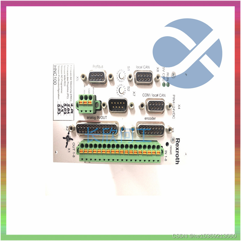
您可以使用数字电压表来确保REXROTH VT-HNC100-1-23/W-08-P-0系列机箱中的所有电压水平都在允许的范围内。参考表2-5,将电压表的一根引线连接到后面板上8针远程电压监测连接器的电源引脚上。请参阅表2-4,了解远程电压监测连接器的引脚输出图。REXROTH VT-HNC100-1-23/W-08-P-0将电压表的参考导线连接到接地引脚之一。将每个电压读数与表2-5中列出的值进行比较。
On the rear panel of the chassis there is an Inhibit Mode switch. Refer to Figure 1-2, Rear View of the NI PXIe-1085 Series Chassis, for the location. The Inhibit Mode switch should be in the Default position when normal power inhibit switch functionality is desired. If the user needs to power on a chassis without a system controller installed the switch should be in the Manual position. When the Inhibit Mode switch is set to the Manual position, the power supplies are enabled, and you can use the Inhibit signal (active low) on pin 1 of the Remote Inhibit and Voltage Monitoring connector to power off the chassis. To remotely power off the chassis, connect the Inhibit pin (pin 1) to a Logic Ground pin (pin 3 or 8). As long as this connection exists, the chassis will remain off (standby); when you remove this connection, the chassis turns on.
机箱附带的PXI平台服务软件会自动识别REXROTH VT-HNC100-1-23/W-08-P-0系统组件,以生成pxiesys.ini文件。您可以配置整个PXI系统,并通过系统控制器附带的测量和自动化浏览器(MAX)识别PXI-1机箱。MAX创建pxisys.ini和pxisys.ini文件,用于定义PXI系统参数。REXROTH VT-HNC100-1-23/W-08-P-0还提供了一个路由和保留触发器的接口,因此通过DAQmx等驱动程序进行动态路由,可以避免双重驱动和可能损坏触发器线路。有关路由和保留PXI触发器的更多信息,REXROTH VT-HNC100-1-23/W-08-P-0


 被折叠的 条评论
为什么被折叠?
被折叠的 条评论
为什么被折叠?
 到【灌水乐园】发言


