


UEFI SPEC只要求为系统中的Physical Device创建Device Path,而Virtual Device是无需创建Device Path的。每个Physical Device都会对应1个Controller Handle,在该Handle下会安装其对应的Device Path。Controller Handle与Device Path的创建都与UEFI Driver紧密相关,因此有必须先了解UEFI Driver及其行为。
UEFI Driver与Controller的关系
UEFI SPEC定义了UEFI Driver Model, 在这个模型下UEFI Driver可以分成3类:
Bus Driver
Device Driver
Hybrid Driver (兼具Bus Driver和Device Driver的特点)
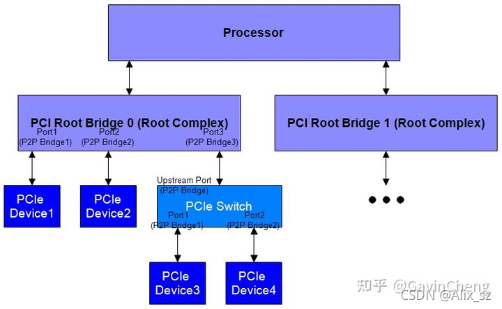
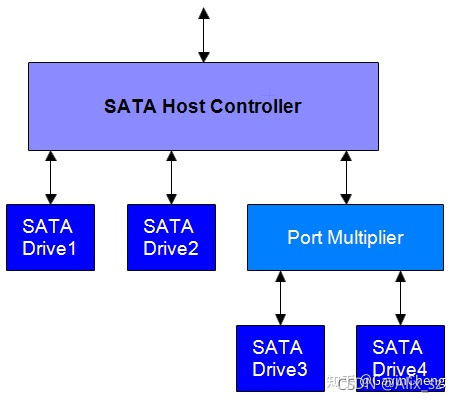
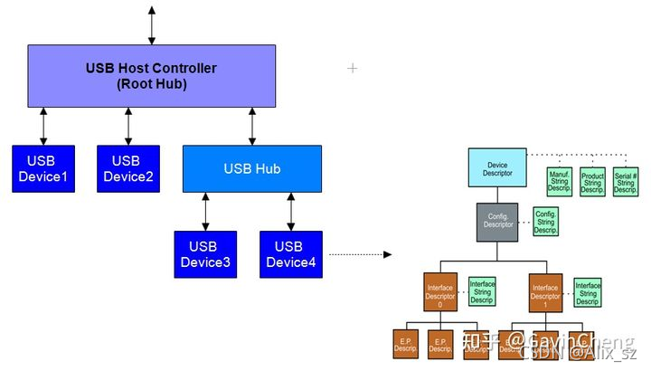
这里区分出了Bus Driver和Device Driver,其实是遵循物理设备在系统内部连接的拓扑层次结构来进行设计。PC中很多Industry总线标准是符合”Host Bus Controller - Child Device Controller“的层级结构的,比如下面示例的PCIe、SATA、USB总线都是如此。
| Bus Type | Host Bus Controller | Child Device Controller |
|---|---|---|
| PCIe | PCI Root Bridge,PCI-to-PCI Bridge (in Root Complex or Switch) | PCIe Device |
| SATA | SATA Host Controller | SATA Drive |
| USB | USB Host Controller,USB Hub | USB Device |
Example 1: PCIe总线拓扑层次结构
Example 2: SATA总线拓扑层次结构
Example 3: USB总线拓扑层次结构
可以简单地这样来理解UEFI Driver和Controller的关系:
Bus Driver负责初始化Host Bus Controller,侦测并枚举Host Bus Controller以下的所有连接到该总线的设备,这些设备统称为Child Device Controller。
Device Driver负责初始化上述1个或者多个Child Device Controller。
UEFI Bus Driver Connect时为Child Device Controller产生Device Path
EFI_BOOT_SERVICES.ConnectController()
UEFI Bus Driver只有在Connect到对应的Host Bus Controller时才会被执行,这个过程通过调用 EFI_BOOT_SERVICES.ConnectController()来发生。这个API的参数接口简单解释如下:
ControllerHandle – 目标Host Bus Controller的Handle。
DriverImageHandle – 代表UEFI Bus Driver的Image Handle List,可以包含多个UEFI Bus Driver。通常为NULL,表示用所有的UEFI Bus Driver来对该Host Bus Controller执行Connect操作。
RemainingDevicePath – 指向Host Bus Controller下面的Child Device的Device Path。通常为NULL不指定。
Recursive – 如果为TRUE,则会沿着Host Bus Controller往下穷尽对所有层次的Child Device的枚举遍历。通常为TRUE。
UEFI Bus Driver Connection过程
上述UEFI Bus Driver Connect到Host Bus Controller的过程简化如下:
1.执行UEFI Bus Driver的服务EFI_DRIVER_BINDING_PROTOCOL.Supported(),该服务会判断目标Host Bus Controller是否为该UEFI Bus Driver适用的设备,如果不适用则直接结束。
2.如果判断UEFI Bus Driver和目标Host Bus Controller匹配,接着执行UEFI Bus Driver的服务EFI_DRIVER_BINDING_PROTOCOL.Start()。在这个服务中,完成上述说的初始化Host Bus Controller和枚举Child Device Controller的过程。
3.每当枚举到1个新的Child Device Controller,都要:
为该Device创建1个Controller Handle。
在该Controller Handle下安装1个Device Path Protocol,也就是创建1个Device Path。
创建Device Path的方法是:先为该Child Device创建对应的Device Path Node,然后将该Node追加到其Parent Device的Device Path尾部形成1个新的Device Path。比如:Child Device (PCI Device=0x0, PCI Function=0x0) 是接在某个PCIe Root Port (PCI Device=0x1C, PCI Function=0x4)下的PCIe Device,其Parent Device的Device Path=PciRoot(0x0)/Pci(0x1C,0x4),该Child Device的Device Path Node为Pci(0x0,0x0),所以它最终的Device Path=PciRoot(0x0)/Pci(0x1C,0x4)/Pci(0x0,0x0)。
Host Bus Controller的Device Path产生
以上是UEFI SPEC定义的Child Device Controller的Device Path的产生过程,那么Host Bus Controller呢?它也属于Physical Device,也需要提供Device Path。针对这一点,UEFI SPEC并没有定义产生的标准流程。不过,系统的UEFI固件对平台上的Host Bus Controller有完全的了解,它会实现为所有Host Bus Controller创建Controller Handle并安装对应的Device Path。
其他情况下产生Device Path
某些UEFI Driver并不初始化Host Bus Controller并枚举Child Device,但是仍然产生Child Device Handle并安装Device Path,它们也被广义上看作UEFI Bus Driver。典型的例子包括Graphics Driver、Serial Driver、LAN Driver、Console Driver等,下面简单说明。
Graphics Driver产生Device Path
Graphics Driver用来初始化系统集成的或者外接显卡上的Graphics Controller,这些Graphics Controller往往不止有1个Graphics Output接口 (比如笔记本上有集成的LCD显示和HDMI接口等)。这些不同的Graphics Output在物理或者逻辑上被Graphics Driver视为不同的Child Device,Graphics Driver在初始化时会侦测并枚举它们,因此会给这些Child Device创建Handle并产生Device Path。值得一提的是,这种Device Path的最后1个Device Path Node是ACPI _ADR Device子类型的(如下面的例子),其值代表了1个表示display output device的UID,具体定义参考ACPI SPEC 6.3 B.5.1 _ADR。PciRoot(0x0)/Pci(0x2,0x0)/AcpiAdr(0x80011400)
LAN Driver产生Device Path
该Driver会针对对应的网卡创建1个Child Device Handle并产生如下Device Path:
1.代表网卡MAC地址的Device Path,比如PciRoot(0x0)/Pci(0x1F,0x6)/MAC(54E1AD76ACEB,0x0)。
2.代表网卡IPv4和IPv4地址的Device Path,比如:
PciRoot(0x0)/Pci(0x1F,0x6)/MAC(54E1AD76ACEB,0x0)/IPv4(0.0.0.0)
PciRoot(0x0)/Pci(0x1F,0x6)/MAC(54E1AD76ACEB,0x0)/IPv6(0000:0000:0000:0000:0000:0000:0000:0000)
其Parent Device Path是对应网卡设备的PCI Device Path=PciRoot(0x0)/Pci(0x1F,0x6)。
Console Device Path
Serial Port和Keyboard/Mouse都是常见的Console In Device,相应的Driver会为它们创建Child Handle并产生Device Path。
以下是几个例子:
PciRoot(0x0)/Pci(0x1F,0x0)/Acpi(PNP0303,0x0) => PNP0303代表Keyboard
PciRoot(0x0)/Pci(0x1F,0x0)/Acpi(PNP0F03,0x0) => PNP0F03代表Mouse
PciRoot(0x0)/Pci(0x1F,0x0)/Acpi(PNP0501,0x0) or PciRoot(0x0)/Pci(0x1F,0x0)/Serial(0x0)=> PNP0501代表Serial Port
关于PNPXXXX与实际设备的对照关系,可以参考下面的Device List。
Device List
download.microsoft.com/download/1/6/1/161ba512-40e2-4cc9-843a-923143f3456c/devids.txt
References
UEFI Bus Driver – 3.10.2 Bus driver
edk2-docs.gitbook.io/edk-ii-uefi-driver-writer-s-guide/3_foundation/readme.10/3102_bus_driver
Graphics Driver – 23.2.3 Driver Binding Protocol Implementation
edk2-docs.gitbook.io/edk-ii-uefi-driver-writer-s-guide/2
转载自:
https://zhuanlan.zhihu.com/p/351926214


 685
685

 被折叠的 条评论
为什么被折叠?
被折叠的 条评论
为什么被折叠?
 到【灌水乐园】发言


