


This series of articles are the study notes of "An Arduino platform and C Programming", by Prof. Harris, Department of Computer Science, University of California, Irvine. This article is the notes of week 1, lessen 1.
week1 - Arduino Environment
1. Lesson 1
1.1 Lecture1-1: Arduino Platform
So in this lesson, we'll talk about the Arduino Environment in general. So that includes the Arduino itself, but also the software environment and the other hardware components that you can add on to an Arduino.
1.1.1 A development board
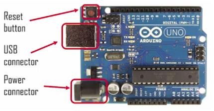
The Arduino Environment starts off with the Arduino development board itself. It looks like this.
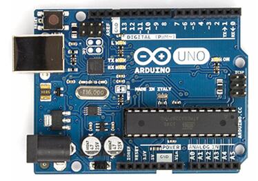
Arduino UNO
A development board
- 8-bit microcontroller (ATmega328 in Arduino UNO)
- programming hardware
- USB programming interface
- I/O pins
So there's an eight bit microcontroller on there, the big chip you can see is an eight bit microcontroller. And there are the chips in there too to interact with the USB and things like this. There's other hardware on there, to allow you to program the microcontroller. So through the USB, so the USB port, you can see that at the top left. That is the cable that is going to be connected to the desktop laptop. Your code will go across that cable when you want to program it. There is a chip in there that communicates with the USB that allows the transferred data to the microcontroller.
1.1.2 Arduino Environment
Arduino also has a software environment, an IDE.IDE stands for Integrated Development Environment and you can see an image of it here. Basically what this is for is for coding. You write the code in there. And by the way, technically you don't have to use the Arduino IDE. You could program an Arduino using eclipse or some other IDE if you want to. You can write code in there, you can compile the code. You can program it, upload it to your board. You can download this from the website,arduino.cc. You can go there and download this, then install it on your machine. It works on every platform, Windows, Linux or Mac.
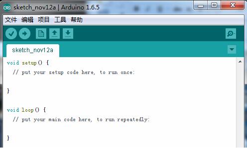
Arduino IDE
A sofeware environment
- cross-complier
- debugger
- simulator
- programmer
1.1.3 Arduino Shields
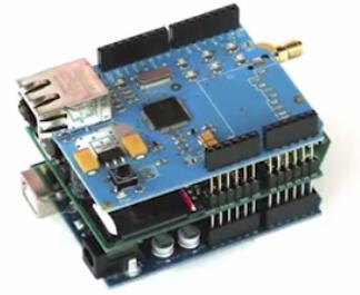
Arduino Shields
Special-purpose“shields”
- daughter boards
- unique functionalities
- easy to attach
- good libraries provided
If you look here, you've got a stack of three boards. It's a little hard to see but there's a stack of three boards. On the top is actually the Ethernet controller shield. And we'll work with this later in the course. But the Ethernet controller shield it’s got an Ethernet jack which you can connect to the Ethernet with, a wired connection. And in the middle of that there's a chip, an integrated circuit which is called an Ethernet controller. And it is needed to manage the Ethernet connection. Now, if you were to do this from scratch, connect to an Ethernet controller chip, it would be a lot of work. The data sheet on that Ethernet controller, actually, I think I've used that Ethernet controller.
Without the shield, the Ethernet controller looks like it has 80 pins on the side. You are going to wire all that up. But what happens with these shields is they basically prewire everything. So they give you a board, a little shield, which has the chip on that prewired. You take that board; you stack it on top of the Arduino. So it has pins going out underneath the board, and you stack it on top. It goes into the holes on the Arduino board. So it is immediately just wired for you to the Arduino. You don't have to do any work.
It comes with a set of functions that are premade, that do everything interesting you need to do. So you don't have to understand almost anything about what the Ethernet controller chip does and how it works.You can just call these library functions and they will send messages and do all the basic things. And it makes it very simple for you, even if you don't know anything about hardware. So, this is another important part of the environment. It's part of why Arduino is so popular.
1.1.4 It’s open sources
If you go to their website, you'll find the schematics for that board. The different components on that board and how they are wired together so if you wanted to, you could take that anddesign your own board, because it's open source. It's open design. It's much cheaper to just buy the pre made board. You could modify it if you wanted to. And there's a large open source community in there that uses it. The hardware is open source;the IDE is also open source. It's written in Java and it is open source, so you can take that and modify it if you want to.
1.2 Lecture1-2: Arduino Board
So we'll continue to talk about the Arduino board. Talk about the different components on the board.
1.2.1 Input/Output pins
This is the input output pin to the board. So you can see at the top and the bottom in red, we circled these pins. And each one of those pins on the board is a hole, a hole in the board that fits a wire. So, you stick the wire in the hole and those holes on the top and the bottom are wired or connected through traces on the board. They're connected to the pins of the actual chip of the main processor down there. So if you wanna connect to that chip, the microcontroller chip, you connect to those I/O pins on the top or on the bottom that we've highlighted in red.
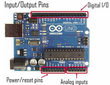
input output pins
(1) Digital I/O
Now on the top you can see thedigital I/O pins. Those pins are meant to be,they take digital inputs and outputs. They drive digital outputs and they take digital inputs. So, by digital, this Arduino UNO board is zero volts or five volts. So 0V means zero, and 5V means a one. Now there are other Arduino boards, not this one, that run at 3.3 volts. So zero to 3.3V.
(2) Analog I/O
Now the ones on the bottom, some of those areanalog inputs. So you can see the ones we've highlighted analog inputs. Those can take analog data on the input. The voltages don't have to be zero volts or five volts, they can be in between andthat information can be read by the microcontroller.
So those inputs are the only ones that you can drive with analog inputs. Note thatit doesn't provide analog outputs in a direct way, because it's a digital the processor itself is a digital processor. So itcan't drive analog outputs, but it can accept analog inputs. Because it has an analog converter built into the microcontroller.
(3) Power reset pins
Other pins down there, the power reset pins. Power reset pins are generally outputs. They have the ground and the power on. They have five volt power, 3.3 volt power, and several grounds. Those are on those pins, and often, when you're connecting, when you're wiring a circuit, connecting it to the board. You'll maybe take power from the five volts from the board, from the Arduino board wired to your circuit, and also you'll want to have a common ground between your Arduino board and your circuits.
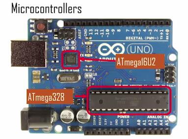
1.2.2 Microprocessors
(1) ATmega328 is programmed by the user
Those pins, you're going to be using those all the time, because that's how the processor interacts with the world, with the senses and the actuators. Now, two other important features on this board are the microprocessors now this board actually has two microcontrollers on it. The main one is that big one down there the ATmega328. That is a processor that the user is programming. So your code, when you write it and compile it gets written into that ATmega328 and the ATmega328 executes the code.
(2) ATmega16U2 handles USB communication
Now in addition to that processor, there's this other micro-controller, the ATmega16U2, and that is there just to handle the communication with the USB. So, USB is a protocol, and that processor, all it does is it understands the USB protocol. So data that comes in on the USB, it translates it to something that the main processor can understand and it passes it on to the main processor. And when the main processor wants to write something to USB, it translates that into USB protocol and sends it out so that process, that ATmega16U2, you won't ever directly access.
1.2.3 Firmware
Now, the ATmega328 that you're going to be working with, and any microcontroller really, has let's say, broadly defined,two types of code running on the microcontroller.
(1) Application code
One type of code, we'll call applicationcode. That is a code that you as a programmer are generally going to write. That is a program that doesn't come with the microcontroller; you write that for your particular application. You're going to write code to do that and youwould call that application code. So we write the code, or you, the programmer, write the code, and it executes the main functionality of the system, directly.
(2) Firmware
Now, besides this application code, systems typically have firmware. Now,firmware is low level code that supports the main function, but doesn't directly perform the main function. Soit does all the background stuff, like the USB interface.
The Arduino has to talk to the USB interface. And you, as a programmer, you don't have to directly figure out how to talk on the USB interface, but the Arduino has to know how. So it has code in there dedicated to talking on the USB interface. Bootloader code does some of that.
Power modes, right. Changing the power modes from low power to high power mode, that happens in the background. You as a programmer don't have to see that.
Reset, when the reset button is pressed, what happens to the device, that's all code that you as a programmer don't have to write.
That stuff is already programmed in there. Generally, you call that firmware. So the programmer doesn’t write it, but its code that’s sitting on the Arduino anyway, and comes with the Arduino. So when you buy the Arduino on that microcontroller, it already has firmware built in to it.
1.3 Lecture1-3: Direct Programming
So, this time, we'll talk about how to program the Arduino, not through the normal way, not through the regular USB route, but to directly program the firmware on the processors. Now, this is not something that you will typically need to do, but we're going to talk about it anyway because every once in a while you might want to upload the bootloader to change the bootloader, update it, and it's good for you to hear how you do that. Because it's not the regular programming process through the IDE that we normally do.
1.3.1 Boot loader
(1) Bootloader is the name of the firmware on themicrocontroller
So the bootloader is the name of the firmware on the microcontroller. And a bootloader is just a generic term for the software, it's not just an Arduino thing, this is just any kind of imbedded system, microcontroller, generally, has bootloader code written into the flash.
(2) It allows a flash and the EEPROM to be programmed
It allows a flash and the EEPROM a non-volatile memory to be programmed so that's what you do when you upload your code.You upload your code,it has to be copied or programmed into the flash memoryor the EEPROM, but usually flash, and so in order for that to happen there has to be code executed on the at mega328 that allows that to happen.
(3) Manages USB communication, since application programming is via USB
Bootloader communicates with the USB interface and does this.So to allows flash or EEPROM to be programmed is main job of the bootloader. The bootloader does a few other things but that's its main job, to allow the flash to be re-written and the EEPROM.
1.3.2 In-CircuitSerial Programming (ICSP)
(1) A special programming method to program the firmware
ICSP is an interface to the board, the special pins on the board through which you can program the bootloader. Now,you can program anything, but it's just sort of a more direct route. Non-USB route. To program the processors on the board, the microcontroller's on the board and the only time you would ever need to use ICSP is if you want to update your bootloader. Because otherwise if you're just updating authentication code, you would use a normal USB route, but the ICSP ports are made so you can update the bootloader directly, and the firmware.
(2) Needed because the bootloader can’t reprogram itself
If you want to update the bootloader you can't do it through the normal USB interface using the bootloader. Instead you have to use a different interface. So that's what In-Circuit Serial Programmingis for ICSP.That's an interface to program the board load, the special pins on the board through which you can programthe bootloader.

If you look at the board, there are two ICSP ports because there are two processors, right. There's the ATmega328, which is the main one. But there's also the ATmega16U2, which is for the USB communication, and that also has firmware on it.


 2607
2607

 被折叠的 条评论
为什么被折叠?
被折叠的 条评论
为什么被折叠?
 到【灌水乐园】发言


