


This series of articles are the study notes of " Interfacing with the Arduino", by Prof. Harris, Department of Computer Science, University of California, Irvine. This article is the notes of week 1, lessen 3.
3.1 Lecture 3.1 - Wiring
Schematics are important. A schematic diagram is a diagram that shows you what the circuit is supposed to look like, how things are connected, how they will be connected in the real device. So it shows how they're gonna be connected.
3.1.1 Interpreting a Schematic
- Shows how components are connected in a real circuit
- You need to be able to build a real circuit from a schematic
you need to understand schematics. So on the one hand, you need to be able to build a circuit given a schematic. So if somebody gives you a schematic, you need to be able to wire things accordingly.
Also, even if you're not taking somebody else's schematic, you have to be able to draw your own schematic. So, say you're making a new device, you put together in your head how things should be connected. You need to be able to write that down in the form of a schematic. So you need to be able to take your design ideas, draw a schematic appropriately that sort of matches the connections that you think are necessary.
3.1.2 Solderless Breadboard
once you have a schematic, you eventually have to wire that schematic up. You have to take that schematic, which is a symbolic representation of the circuit, and you have to make it a real circuit. So you have to wire up the components according to the schematic. Now we're gonna do that in this class and we're gonna use, for wiring, we're gonna use the solderless breadboard.
(1) Breadboard
Now, basically what we're using breadboard for it? The idea is that, when you're wiring things up, wiring together a circuit, you have to connect wires together. So say I want one resistor connected to another resistor, I gotta take one wire with one resistor, the other wire to the other resistor, and connect them together. And we're gonna use this Solderless breadboard for that purpose.
(2) Soldering
Now, another way to go about this, which we will not cover in this class, but another way to go about it, is to do soldering. Soldering is where you take the two wires that you want to connect, you put them together, right, and there's a joint. Then you take a hot iron, okay. You heat the joint, so you put the hot iron to the joint to heat it up. Then you take a piece of solder, solder is a metal, a soft metal with a relatively low melting point, and you take that solder and you touch it to the joint. That solder melts, and you pull away the solder, but you get a little glob of solder on the joint that's melted and is now connecting the two pieces of wire. Okay, that's soldering.
Soldering is a more permanent way of doing things. So it's a much more secure bond. It has good physical strength, also good conductivity
(3) Solderless breadboard

A solderless breadboard is much easier, because you can just take the wire, stick it in a hole, pull it out the hole, okay. Easy to re-do things, it's great for prototyping, which is what we're doing here. So, solderless breadboards, they allow components to be easily connected in a non-permanent way. Great for prototyping what we're doing.
- Allows components to be easily connected in a non-permanent way
- Great for prototyping
- Holes fit 24 AWG (American Wire Gauge) solid wire
- Connected in rows of 5 holes and columns along the sides
Now notice that in addition to these rows of five, you got rows of five on the left, rows of five on the right, there are these columns on the sides, right, these long columns. Actually they're grouped in five. Basically they're long columns, and you can see I've highlighted them in green too, these vertical columns. So those vertical columns are connected differently. They are not connected in groups of five, the entire column is connected. In each one of these four columns on the sides. Now, those columns are generally meant for power and ground.
3.1.3 Wiring Process
(1) Select a hardware component
(2) Select one terminal on the hardware component
(3) Connect the terminal to a row of the breadboard
- If the terminal needs to be connected to another terminal already in the breadboard, shared the row
- Otherwise, use a free row
(4) Go back to step 2 until all terminals are done
(5) Go back to step 1 until all components are done.
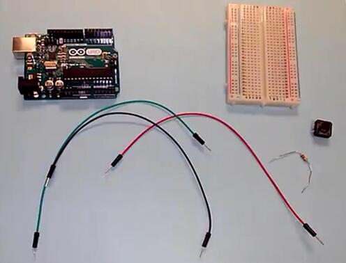
3.2 Lecture 3.2 - Wiring Demo, Pushbutton
The demo code that we're gonna run on the Arduino, you can find it in the examples. So if you go to examples, if you start your Arduino.ide, go to examples, the digital subcategory, and look at an example called button. That's what we're gonna make. So what that'll do is, it'll turn on a light an LED. Specifically, the LED connected to pin 13.

<div style="text-align: justify;"><span style="font-family: Arial, Helvetica, sans-serif;">// set pin numbers:</span></div><div style="text-align: justify;"><span style="font-family: Arial, Helvetica, sans-serif;">const int buttonPin = 2;     // the number of the pushbutton pin</span></div>const int ledPin =  13;      // the number of the LED pin

<div style="text-align: justify;"><span style="font-family: Arial, Helvetica, sans-serif;">int buttonState = 0;         // variable for reading the pushbutton status</span></div>// variables will change:

void setup() {
  // initialize the LED pin as an output:
<div style="text-align: justify;"><span style="font-family: Arial, Helvetica, sans-serif;">  pinMode(buttonPin, INPUT);</span></div>  pinMode(ledPin, OUTPUT);
  // initialize the pushbutton pin as an input:
}

void loop() {
<div style="text-align: justify;"><span style="font-family: Arial, Helvetica, sans-serif;">  // check if the pushbutton is pressed.</span></div>  // read the state of the pushbutton value:
  buttonState = digitalRead(buttonPin);

  // if it is, the buttonState is HIGH:
<div style="text-align: justify;"><span style="font-family: Arial, Helvetica, sans-serif;">    digitalWrite(ledPin, LOW);</span></div>  if (buttonState == HIGH) {
    // turn LED on:
    digitalWrite(ledPin, HIGH);
  }
  else {
    // turn LED off:
  }
<div style="text-align: justify;"><span style="font-family: Arial, Helvetica, sans-serif;">}</span></div>
3.3 Lecture 3.3 - Wiring Demo, Potentiometer
Now we're gonna work with a potentiometer. We're gonna wire together, wire it to the Arduino. And we're gonna run a program. That will blink a light, an LED on the Arduino and blink it according to how much we've turned the potentiometer. So what resistance we've measured across the potentiometer.
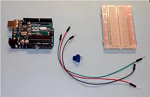
The name of that program is called Analog Input. So if you look in your examples, if you start your IDE, go to examples. Look in the subcategory number three called analog. And then the program called Analog Input, that's the one we're using.

<div style="text-align: justify;"><span style="font-family: Arial, Helvetica, sans-serif;">int sensorPin = A0;    // select the input pin for the potentiometer</span></div>int ledPin = 13;      // select the pin for the LED
<div style="text-align: justify;"><span style="font-family: Arial, Helvetica, sans-serif;">int sensorValue = 0;  // variable to store the value coming from the sensor</span></div>
void setup() {
  // declare the ledPin as an OUTPUT:
  pinMode(ledPin, OUTPUT);
}

void loop() {
<div style="text-align: justify;"><span style="font-family: Arial, Helvetica, sans-serif;">  digitalWrite(ledPin, HIGH);</span></div>  // read the value from the sensor:
  sensorValue = analogRead(sensorPin);
  // turn the ledPin on
<div style="text-align: justify;"><span style="font-family: Arial, Helvetica, sans-serif;">  // stop the program for for <sensorValue> milliseconds:</span></div>  // stop the program for <sensorValue> milliseconds:
  delay(sensorValue);
  // turn the ledPin off:
  digitalWrite(ledPin, LOW);
  delay(sensorValue);
<div style="text-align: justify;"><span style="font-family: Arial, Helvetica, sans-serif;">}</span></div>
Some uesful picture for homework 1.
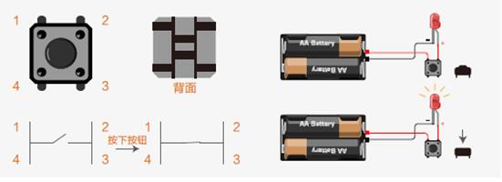
Push Button structure

LED circuit
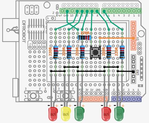
Push button circuit


 9077
9077

 被折叠的 条评论
为什么被折叠?
被折叠的 条评论
为什么被折叠?
 到【灌水乐园】发言


