


This series of articles are the study notes of "Interfacing with the Arduino", by Prof. Harris, Department of Computer Science, University of California, Irvine. This article is the notes of week 2, lessen 2.
2. Lesson 2
2.1 Lecture 2.1 -Actuators
2.1.1 Actuators
(1) Devices that cause something to happen in the physical world
IoT devices have a set of actuators that cause something to happen in the real world. Because IoT devices have to do something, have to have some output. And the output goes to actuators and they cause some event in the real world. This event in the real world might be as simple as putting a message on a screen, right. But it could be more sophisticated than that. Basically, actuators are the outputs of the IoT device.
(2) Outputs of the IoT device
- Visual: LED, LCD, monitor
- Audio: buzzer, speaker
- Motion: motors, valve, pump
- Tactile: heating, cooling
2.1.2 On-Off Actuators
(1) The only control is power
Actuators are just devices that do something in the real world. Now, the simplest type of actuation you can have is what I'll call on-off actuation or power actuation. And all you're doing is controlling the power, the only control that you have with this device is power.
(2) Even complicated actuators can be controlled via power
- LED, buzzer, monitor, etc.
Now this is very simplistic control. So even complicated actuators can be controlled via power. Minimal control, but you can do something via power. So LEDs, light emitting diodes, you can just turn them off and on. Now you can be more sophisticated about that. You can make them brighter or darker and all that, but you don't have to. You can just say off, on. You can control them in this digital way. A buzzer, you can make it buzz or not buzz. A monitor, you can power it on or off. Now there are all kinds of devices like that. Basically all devices, you can give,
you could just control them through power, on, off.
(3) Does not use the full potential of the actuator
Now this, for complicated actuators, this doesn't use the full potential of the actuator. Meaning like with a monitor. With a monitor you can put up messages on there, draw pictures on there, all kinds of sophisticated things. But if you're doing on-off actuation, all you can do is turn it off and on. So you're controlling it but in a minimal way. With an LED. LED off and on is often enough, but you could make it dimmer or brighter. But with on-off actuation, that's not possible. So this is one way to control an actuator, just through power.
(4) On-Off control may be all that is necessary
- Lights in a class room, air conditioning
On-off control may be all that you need. It depends on the application. Maybe all you need it to turn your LED off or on, in which case on-off actuation is just fine. Lights in a classroom, yes, so like in my office when you walk into the room, the light sensor turns the lights on. And it doesn't set the lights at a certain dimness or brightness or something like that, it's that either they're all on or all off. So it's sufficient. Also, air conditioning, like HVAC systems. Typically, like in my office, the air is on or it's off. It doesn't get in between. So that's mostly satisfactory.
2.1.3 Current Limits
(1) Watch out for current limits
One thing to worry about or to be aware of when you're actuating something and especially in this power mode is to think about the current limits of the device, of both devices on both sides, so your micro controller and your actual actuator. Think about the current limits.
(2) LED can only handle 20mA
- Be sure to use an appropriate resistor
So for instance, an LED, typical LED might only be able to handle 20 milliamps, so you cannot drive it with more than 20 milliamps without hurting it. So you got to make sure somehow that that it only is driven with 20 milliamps. So for instance, putting in an appropriate resistor in series with the LED will, using V = IR, you can put the right size resistor to make sure the current never exceeds a certain threshold.
(3) Arduino can only supply 40mA
Now you also have to think about current limits on the other side, on the supply side. So the Arduino, regular Arduino pins or Arduino UNO, regular pins besides the power and ground, the power pin, rather. Regular pins can only supply 40 milliamps. So if you are driving something that needs more than 40 milliamps you may have a problem.
- Cannot drive a motor that requires 15 Amperes!
So for instance, if you got a motor that request 50 amperes, then 40 milliamps is clearly not enough. And I say 15 amperes because I think about my quad-copter, and those motors can take 10 amperes, 15 maybe. They require a lot of power and the Arduino would never be able to supply that level of power.
- May need to use alternate power supply
So in a situation like that, the Arduino can't supply it, so you need some other power supply. So like on a quad-copter, there's a big fat battery on the bottom, and that is the power supply.
- Arduino can control access to power without providing power directly
The Arduino that I use to drive the motors doesn't actually directly feed power to the motor. Instead, the Arduino controls the switch between the battery, the big battery, and the motor. So it controls access to the power in that sense.
So you going to be aware of these current limits. The Arduino itself can only supply a certain amount of current. So, if you need more than that then you need an alternate power supply. The device that you are actuating, say a LED, might only be able to take a certain amount of current. And you've got to make sure the Arduino or whatever device it is that drives it, can't supply more current than is necessary, than it can take.
2.2 Lecture 2.2 - Analog Actuators
2.2.1 Analog Voltage Control
(1) Many actuators need an analog voltage for complete control
Several actuators are controlled using analog voltage. It's a common thing. So, to completely control them, to make them do everything they need to do, you need to supply an analog voltage to them.
- DC motor
For instance, a DC motor. A DC motor, the speed of the motor is controlled by the analog voltage that it receives, so if you give it more voltage, it'll go faster, and so on.
- LED
And LED you can control it in binary zero one, but you can also give it an analog voltage to make it brighter or dimmer.
- Heating elements
Heating elements so for instance in a toaster you know hot wire, that type of thing. It's going to heat up. It will output as much heat as it gets. So if you increase the voltage it will have more energy so it make it hotter.
(2) Arduino cannot generate analog voltage
So, there are a lot of devices like this, a lot of actuators like this, that require an analog voltage, but an Arduino cannot generate analog voltage. Arduinos can do digital write, which is a digital voltage, but outputting an analog voltage. Now there is a function called analog wright, and I will describe this function. But it does not directly produce an analog voltage on the output. So say you wanna output 2.5 volts on one of the pins. You can't do that with an Arduino, or with a microcontroller inside an Arduino. Actually most microcontroller don't have don't have that ability. Now I should say that an Arduino Due, which is a more expensive Arduino, I believe it can output analog directly, but it is very common that components can't output analog directly.
2.2.2 Digital to analog converter (DAC)
Now, one way to fix that is to buy a digital to analog converter, which I think is actually probably on the Arduino Due. It's a separate chip. A separate integrated circuit that you can connect to your microcontroller.
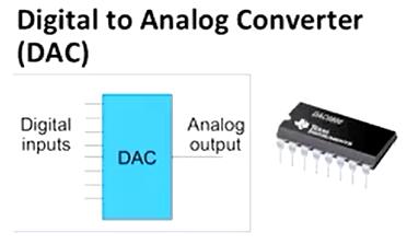
(1) DAC will convert digital number to an analog voltage
And it'll take, actually we show a schematic of it up there. It'll take-send digital inputs, like in this case, it's an 8 bit number, so 8 digital inputs, zeros and ones. And it'll output an analogue voltagevalue according to those digital inputs. So, for instance, If you want to output, this is a rough approximation of what would happen. Say you want to output 3 volts on the analog output. So you would drive the digital inputs with the number 3 in binary. Which is 11. You drive that. And then the analog output would be 3 volts. So it takes the digital inputs and converts it to an equivalent analog value.
So if you have one of these chips, you could interface that with the Arduino, whatever might controller it is, and get analog voltage values.
(2) Most microprocessors do not have a DAC
Most microprocessors do not have, most microcontrollers anyway don't have this built in. But
you can add a separate chip and attach it, wire it up. We'll talk about things like that later, but
it might be expensive. It might cost you, because you have to buy the digital analog converter and connect it up. Might be a little bit complicated, but that can certainly be done. But that's a more expensive option, usually that's not necessary.
2.3.2 analogWrite()
Now
analogWrite() does exactly this, it generates a pulse width modulated signal.
(1) Generates a square wave on a pin, 490 Hz
So it generates a square wave on a pin, it's 490 Hz. Now Hz is cycles per second. So how many clock pulses? 490 clock pulses every second. That's how fast this clock is changing, how fast the square wave is changing.
(2) The first argument is the pin number
This analogWrite() takes two arguments. The first argument is a pin number. The pin that you want to generate the pulse width modulated signal on.
(3) The second argument is the pulse width
- 0 is 0% duty cycle
- 255 is 100% duty cycle
- 127 or 128 is 50% duty cycle
The second argument is the pulse width, or an indication of the pulse width. So the second argument in a number from 0 to 255. And that number indicates how wide the pulse is. So, 0 means you have a 0% duty cycle, which means it's low all the time. 255 is the max, so that would mean 100% duty cycle. If you wanted 50% duty cycle, you'd do halfway in between. So, 128 and 127. That'd be 50% duty cycle. And you can change duty cycle by changing that second argument.
(4) Pin number must be a PWM pin
- Marked on the Arduino with the ~ symbol
Arduino only allows you to generate the pulse width modulated signal on a subset of the pins. If you look at your Arduino, the numbers of the pins, there'll be a little tilde, squiggle mark, next to the pins that you're allowed to do pulse width modulation on.
(5) An example analogWrite(3, 128)
So an example, you might say
analogWrite(3, 128). That would say on pin 3 we're going to drive that with a square wave. And 128 is it's duty cycle. Now since that's halfway between, or almost halfway between 0 and 255, you'd expect a 50% duty cycle for that.
2.3.3 Fade Example
Now, here's an example piece of code. This is actually in your example, so if you open up your Arduino IDE. Go to file, examples, I believe this is in the basics. File examples, basics. There's one called Fade, and that's this.
int led = 9;           // the pin that the LED is attached to
int brightness = 0;    // how bright the LED is
int fadeAmount = 5;    // how many points to fade the LED by

// the setup routine runs once when you press reset:
void setup() {
  // declare pin 9 to be an output:
  pinMode(led, OUTPUT);
}

// the loop routine runs over and over again forever:
void loop() {
  // set the brightness of pin 9:
  analogWrite(led, brightness);

  // change the brightness for next time through the loop:
  brightness = brightness + fadeAmount;

  // reverse the direction of the fading at the ends of the fade:
  if (brightness == 0 || brightness == 255) {
    fadeAmount = -fadeAmount ;
  }
  // wait for 30 milliseconds to see the dimming effect
  delay(30);
}
So, first notice there the normal two functions, the setup and the loop. All this does, just to zip right to what it does, there is an LED. It assumes that there is an LED connected on one of the pins. Actually I must have left out that. LED is a variable in here that refers to a particular pin that you've wired an LED on to. Let's assume it's pin 13. Say it's pin 13, because we know there's an LED on that pin. So what all this does is it calls analogWrite on that pin you can see highlighted in red. It called analogWrite on that pin. So it generates a square wave on that pin. And the second argument which is the duty cycle. Which is the indication of the duty cycle, that's the brightness.
So the idea is that
if you have a large duty cycle, 100% duty cycle, then you're gonna get a very bright LED. Bu
t if you have a very small duty cycle,
it's only high a very small fraction of the time, then you get a very dim LED.
And so what this function does, if you look at the loop, it does the analogWrite with a certain brightness, starting at brightness 0, so it would be off. Then it increments brightness, brightness = brightness + fadeAmount, which is something small, say five. Then, if brightness equals 0, or brightness equals 255. So if it reaches an extreme. So you're counting up, right. So you start off with brightness equals 0, then 5, then 10, then so on. Every pass through, becuase this is in a loop, it gets bigger, brighter, and brighter. Then, once it hits the maximum, once it's 255, then it has to change direction. And the fade amount, if it was five, it should become negative five now, so that it gets dimmer. And then if it was -5 and you hit 0, then it should reverse direction and become positive 5. So what this function will do is actually make the LED get brighter and then dimmer, brighter and dimmer over and over. Notice the delay(30). That slows the process down a little bit so you could see it. But that's what this function does, and it uses analogWrite to send a pulse width modulated signal to the LED.


 3万+
3万+

 被折叠的 条评论
为什么被折叠?
被折叠的 条评论
为什么被折叠?
 到【灌水乐园】发言


