


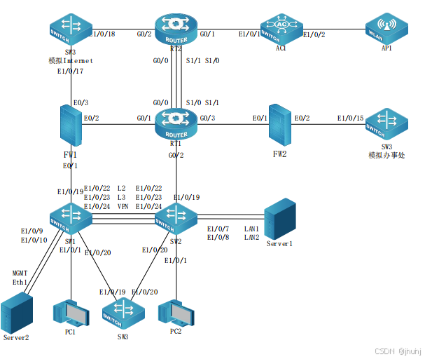
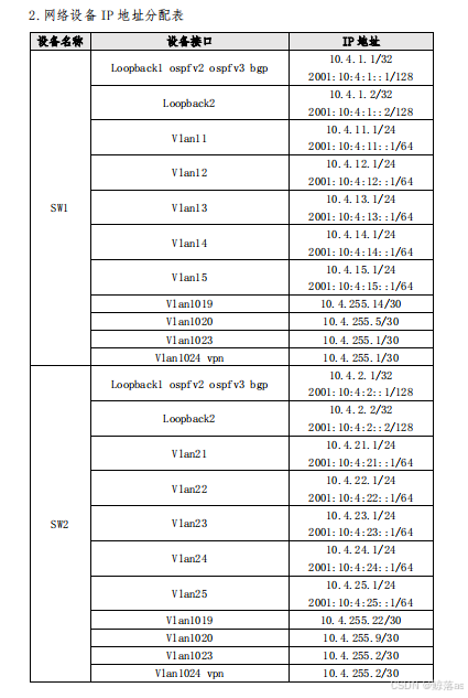
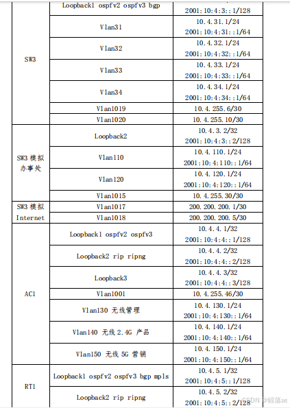
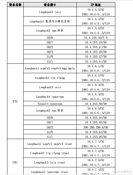
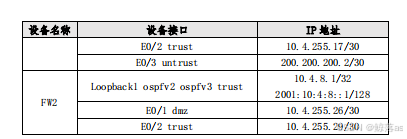
网络拓扑图及 IP 地址表:
SW1:Interface Ethernet1/0/22
switchport mode trunk //设置端口模式为trunk
switchport trunk allowed vlan 11-15 //只允许vlan11-15通过
SW2:Interface Ethernet1/0/22
switchport mode trunk
switchport trunk allowed vlan 21-25
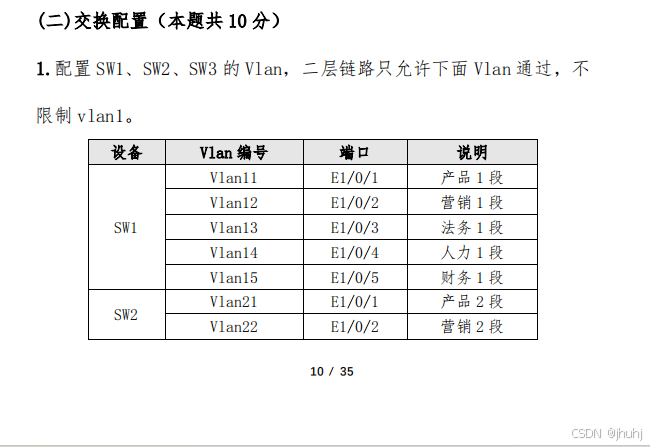
(二)交换配置
2.SW1 和 SW2 之间利用三条裸光缆实现互通,其中一条裸光缆承载三 层 IP 业务、一条裸光缆承载 VPN 业务、一条裸光缆承载二层业务。 用相关技术分别实现财务 1 段、财务 2 段业务路由表与其它业务路由 表隔离,财务业务 VPN 实例名称为 Finance,RD 为 1:1。承载二层业 务的只有一条裸光缆通道,配置相关技术,方便后续链路扩容与冗余 备份,编号为 1,用 LACP 协议,SW1 为 active,SW2 为 passive;采 用目的、源 IP 进行实现流量负载分担。
SW1:
port-group 1 //创建聚合组 1
!
vlan 1;11-15;1019-1020;1023-1024
!
load-balance dst-src-ip 链路聚合按ip进行负载分担
!
Interface Ethernet1/0/1
switchport access vlan 11
!
Interface Ethernet1/0/2
switchport access vlan 12
!
Interface Ethernet1/0/3
switchport access vlan 13
!
Interface Ethernet1/0/4
switchport access vlan 14
!
Interface Ethernet1/0/5
switchport access vlan 15
!
Interface Ethernet1/0/6
!
Interface Ethernet1/0/7
!
Interface Ethernet1/0/8
!
Interface Ethernet1/0/9
!
Interface Ethernet1/0/10
!
Interface Ethernet1/0/11
!
Interface Ethernet1/0/12
!
Interface Ethernet1/0/13
!
Interface Ethernet1/0/14
!
Interface Ethernet1/0/15
!
Interface Ethernet1/0/16
!
Interface Ethernet1/0/17
!
Interface Ethernet1/0/18
!
Interface Ethernet1/0/19
switchport access vlan 1019
!
Interface Ethernet1/0/20
switchport access vlan 1020
!
Interface Ethernet1/0/21
!
Interface Ethernet1/0/22
switchport mode trunk
switchport trunk allowed vlan 11-15
port-group 1 mode active //加入聚合组并配置为主动
!
Interface Ethernet1/0/23
switchport access vlan 1023
!
Interface Ethernet1/0/24
switchport access vlan 1024
!
Interface Ethernet1/0/25
!
Interface Ethernet1/0/26
!
Interface Ethernet1/0/27
!
Interface Ethernet1/0/28
!
Interface Port-Channel1
!
ip vrf Finance //创建财务实例
rd 1:1 //配置实例id
!
interface Vlan11
ipv6 address 2001:10:4:11::1/64
ip address 10.4.11.1 255.255.255.0
!
interface Vlan12
ipv6 address 2001:10:4:12::1/64
ip address 10.4.12.1 255.255.255.0
!
interface Vlan13
ipv6 address 2001:10:4:13::1/64
ip address 10.4.13.1 255.255.255.0
!
interface Vlan14
ipv6 address 2001:10:4:14::1/64
ip address 10.4.14.1 255.255.255.0
!
interface Vlan15
ip vrf forwarding Finance //加入财务实例,与其他业务隔离 注意:加入实例后会清空此vlan的配置,建议先加入实例在配置ip地址及其他
ipv6 address 2001:10:4:15::1/64
ip address 10.4.15.1 255.255.255.0
!
interface Vlan1019
ip address 10.4.255.14 255.255.255.252
!
interface Vlan1020
ip address 10.4.255.5 255.255.255.252
!
interface Vlan1023
ip address 10.4.255.1 255.255.255.252
!
interface Vlan1024
ip vrf forwarding Finance //因为相互隔离,所以ipv4与vlan1023的不冲突
ip address 10.4.255.1 255.255.255.252
!
interface Loopback1
ipv6 address 2001:10:4:1::1/128
ip address 10.4.1.1 255.255.255.255
!
interface Loopback2
ipv6 address 2001:10:4:1::2/128
ip address 10.4.1.2 255.255.255.255
!
SW2:
Interface Ethernet0
!
!
!
port-group 1
!
vlan 1;21-25;1019-1020;1023-1024
!
load-balance dst-src-ip
!
Interface Ethernet1/0/1
switchport access vlan 21
!
Interface Ethernet1/0/2
switchport access vlan 22
!
Interface Ethernet1/0/3
switchport access vlan 23
!
Interface Ethernet1/0/4
switchport access vlan 24
!
Interface Ethernet1/0/5
switchport access vlan 25
!
Interface Ethernet1/0/6
!
Interface Ethernet1/0/7
!
Interface Ethernet1/0/8
!
Interface Ethernet1/0/9
!
Interface Ethernet1/0/10
!
Interface Ethernet1/0/11
!
Interface Ethernet1/0/12
!
Interface Ethernet1/0/13
!
Interface Ethernet1/0/14
!
Interface Ethernet1/0/15
!
Interface Ethernet1/0/16
!
Interface Ethernet1/0/17
!
Interface Ethernet1/0/18
!
Interface Ethernet1/0/19
switchport access vlan 1019
!
Interface Ethernet1/0/20
switchport access vlan 1020
!
Interface Ethernet1/0/21
!
Interface Ethernet1/0/22
switchport mode trunk
switchport trunk allowed vlan 21-25 /加入聚合组一并设置为被动
port-group 1 mode passive
!
Interface Ethernet1/0/23
switchport access vlan 1023
!
Interface Ethernet1/0/24
switchport access vlan 1024
!
Interface Ethernet1/0/25
!
Interface Ethernet1/0/26
!
Interface Ethernet1/0/27
!
Interface Ethernet1/0/28
!
Interface Port-Channel1
!
ip vrf Finance
rd 1:1
!
interface Vlan21
ipv6 address 2001:10:4:21::1/64
ip address 10.4.21.1 255.255.255.0
!
interface Vlan22
ipv6 address 2001:10:4:22::1/64
ip address 10.4.22.1 255.255.255.0
!
interface Vlan23
ipv6 address 2001:10:4:23::1/64
ip address 10.4.23.1 255.255.255.0
!
interface Vlan24
ipv6 address 2001:10:4:24::1/64
ip address 10.4.24.1 255.255.255.0
!
interface Vlan25
ip vrf forwarding Finance
ipv6 address 2001:10:4:25::1/64
ip address 10.4.25.1 255.255.255.0
!
interface Vlan1019
ip address 10.4.255.22 255.255.255.252
!
interface Vlan1020
ip address 10.4.255.9 255.255.255.252
!
interface Vlan1023
ip address 10.4.255.2 255.255.255.252
!
interface Vlan1024
ip vrf forwarding Finance
ip address 10.4.255.2 255.255.255.252
!
interface Loopback1
ipv6 address 2001:10:4:2::1/128
ip address 10.4.2.1 255.255.255.255
!
interface Loopback2
ipv6 address 2001:10:4:2::2/128
ip address 10.4.2.2 255.255.255.255
!
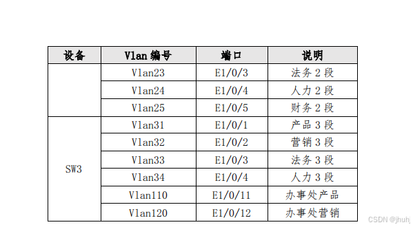
3.为方便后续验证与测试,SW3 的 E1/0/22 连接其他合适设备的一个 接口,配置为 trunk,允许 Vlan31-34、110、120 通过。
4.将 SW3 模拟办事处交换机,实现与集团其它业务路由表隔离,办事 处路由表 VPN 实例名称为 Office,RD 为 1:1。将 SW3 模拟为 Internet 交换机,实现与集团其它业务路由表隔离,Internet 路由表 VPN 实 例名称为 Internet,RD 为 2:2。
SW3:注:sw3的e1/0/22可以连接到SW1,SW2合适的口测试,也可以在端口里设置LOOKBACK测试vlan 1;31-34;110;120;1015;1017-1020
!
Interface Ethernet1/0/1
loopback //模拟端口状态开启,方便后续测试
switchport access vlan 31
!
Interface Ethernet1/0/2
loopback
switchport access vlan 32
!
Interface Ethernet1/0/3
switchport access vlan 33
!
Interface Ethernet1/0/4
loopback
switchport access vlan 34
!
Interface Ethernet1/0/5
!
Interface Ethernet1/0/6
!
Interface Ethernet1/0/7
!
Interface Ethernet1/0/8
!
Interface Ethernet1/0/9
!
Interface Ethernet1/0/10
!
Interface Ethernet1/0/11
loopback
switchport access vlan 110
!
Interface Ethernet1/0/12
loopback
switchport access vlan 120
!
Interface Ethernet1/0/13
!
Interface Ethernet1/0/14
!
Interface Ethernet1/0/15
switchport access vlan 1015
!
Interface Ethernet1/0/16
!
Interface Ethernet1/0/17
switchport access vlan 1017
!
Interface Ethernet1/0/18
switchport access vlan 1018
!
Interface Ethernet1/0/19
switchport access vlan 1019
!
Interface Ethernet1/0/20
switchport access vlan 1020
!
Interface Ethernet1/0/21
!
Interface Ethernet1/0/22
switchport mode trunk
switchport trunk allowed vlan 31-34;110;120
!
Interface Ethernet1/0/23
!
Interface Ethernet1/0/24
!
Interface Ethernet1/0/25
!
Interface Ethernet1/0/26
!
Interface Ethernet1/0/27
!
Interface Ethernet1/0/28
!
ip vrf Office //创建模拟办事处实例
rd 1:1
!
ip vrf Internet //创建Internet实例
rd 2:2
!
interface Vlan31
ipv6 address 2001:10:4:31::1/64
ip address 10.4.31.1 255.255.255.0
!
interface Vlan32
ipv6 address 2001:10:4:32::1/64
ip address 10.4.32.1 255.255.255.0
!
interface Vlan33
ipv6 address 2001:10:4:33::1/64
ip address 10.4.33.1 255.255.255.0
!
interface Vlan34
ipv6 address 2001:10:4:34::1/64
ip address 10.4.34.1 255.255.255.0
!
interface Vlan110
ip vrf forwarding Office
ipv6 address 2001:10:4:110::1/64
ip address 10.4.110.1 255.255.255.0
!
interface Vlan120
ip vrf forwarding Office
ipv6 address 2001:10:4:120::1/64
ip address 10.4.120.1 255.255.255.0
!
interface Vlan1015
ip vrf forwarding Office
ip address 10.4.255.30 255.255.255.252
!
interface Vlan1017
ip vrf forwarding Internet
ip address 200.200.200.1 255.255.255.252
!
interface Vlan1018
ip vrf forwarding Internet
ip address 200.200.200.5 255.255.255.252
!
interface Vlan1019
ip address 10.4.255.6 255.255.255.252
!
interface Vlan1020
ip address 10.4.255.10 255.255.255.252
!
interface Loopback1
ipv6 address 2001:10:4:3::1/128
ip address 10.4.3.1 255.255.255.255
!
interface Loopback2
ip vrf forwarding Office
ipv6 address 2001:10:4:3::2/128
ip address 10.4.3.2 255.255.255.255
!
5.SW1 配置 SNMP,引擎 id 分别为 1000;创建组 GroupSkills,采用 最高安全级别,配置组的读、写视图分别为:Skills_R、Skills_W;12 / 35 创建认证用户为 UserSkills,采用 aes 算法进行加密,密钥为 Key- 1122,哈希算法为 sha,密钥为 Key-1122;当设备有异常时,需要用 本地的环回地址 Loopback1 发送 v3 Trap 消息至集团网管服务器 10.4.15.120、2001:10:4:15::120,采用最高安全级别;当法务部门 的用户端口发生 updown 事件时禁止发送 trap 消息至上述集团网管 服务器。
SW1:snmp-server enable //启动snmp 功能
snmp-server engineid 1000 //配置引擎 id 为 1000
snmp-server user UserSkills GroupSkills authPriv aes b693dfa497e63a03e2b4a1d3709b0723 auth sha b693dfa497e63a03e2b4a1d3709b0723f62da73a //创建用户认证,用户名后跟组名,这里密码Key-1122是因为加密过的,密码配置时换成题目要求的即可
snmp-server group GroupSkills authpriv read Skills_R write Skills_W //创建组,与读写视图
snmp-server host 2001:10:4:15::120 v3 authpriv UserSkills //设置接收端(网管服务器地址,配置最高安全级别)snmp-server host 10.4.15.120 v3 authpriv UserSkillssnmp-server trap-source 10.4.1.1 //配置接受端地址
snmp-server trap-source 2001:10:4:1::1snmp-server host 10.4.15.120 v3 authpriv UserSkills
snmp-server enable traps //启动snmp trap 功能
6.对 SW1 与 FW1 互连流量镜像到 SW1 E1/0/1,会话列表为 1。
SW1monitor session 1 source interface Ethernet1/0/19 both//配置源端口,可以不用加both,默认有
monitor session 1 destination interface Ethernet1/0/1//配置目的端口
7.SW1 和 SW2 E1/0/21-28 启用单向链路故障检测,当发生该故障时, 端口标记为 errdisable 状态,自动关闭端口,经过 1 分钟后,端口 自动重启;发送 Hello 报文时间间隔为 15s;
SW1:uldp enable//启动单向链路故障检测
uldp recovery-time 60//设置重启时间
uldp hello-interval 15//设置hello报文时间间隔
uldp aggressive-mode//发生故障时,相应端口标记为 errdisable 状态int ethernet 1/0/21-28uldp enableuldp aggressive-mode//配置检测相应的端口与标记SW2:同上
8.SW1 和 SW2 所有端口启用链路层发现协议,更新报文发送时间间隔 为 20s,老化时间乘法器值为 5,Trap 报文发送间隔为 10s,配置三 条裸光缆端口使能 Trap 功能。
lldp enable启动lldp功能
lldp msgTxHold 5配置老化时间乘法器
lldp tx-interval 20配置更新报文发送时间间隔lldp notification interval 10配置trap报文发送时间间隔int ethernet 1/0/1-28lldp enable所有端口启用lldp协议int ethernet 1/0/22-24lldp trap enable三条裸光缆端口使能 Trap 功能
(三)路由调试
1.配置所有设备主机名,名称见“网络拓扑”。启用所有设备的 ssh 服 务,用户名和明文密码均为 admin;配置所有设备 ssh 连接超时为 9 分钟,console 连接超时为 30 分钟。
注:所有设备主机名,hostname+主机名,所有设备默认用户名和密码为admin,不用配置SW1-3 AC1:ssh-server enable启用ssh功能ssh-server timeout 540配置ssh连接超时为九分钟,交换机;AC及RT默认以秒为单位exec-timeout 30配置console连接超时为30分钟,交换机;AC默认以分钟为单位RT1-2:ip sshd enable启用ssh功能ip sshd timeout 540配置ssh连接超时为九分钟line vty 0exec-timeout 1800进入虚拟终端配置,配置console连接超时为30分钟,RT默认以秒为单位FW1-2:admin user adminaccess sshpassword Key-1122配置ssh功能并设置密码,输入 password Key-1122 后,会提示 Please input the old password: ,需要输入原密码admin即可修改ssh timeout 9配置ssh连接超时为九分钟,防火墙默认以分钟为单位console timeout 30配置console连接超时为30分钟,防火墙默认以分钟为单位
2.配置所有设备的时区为 GMT+08:00。调整 SW1 时间为实际时间,SW1 配置为 ntp server,其他设备为 ntp client,请求报文时间间隔 1分钟,用 SW1 Loopback1 IPv6 地址作为 ntp server 地址。
SW1:
clock timezone GMT add 8 0
设置设备时区ntp enable
启动ntp功能ntp-service refclock-master 1
设置SW1为ntp 服务器地址SW2-SW3-AC1:
clock timezone GMT add 8 0
ntp enable
ntp server 2001:10:4:1::1
使用SW1 LOOPBACK1 的服务器地址
ntp syn-interval 60
配置请求报文时间间隔 为1 分钟,交换机;AC及RT默认以秒为单位
RT1-2:
time-zone GMT 8 0
配置时区
ntp server 2001:10:4:1::1
使用SW1 LOOPBACK1 的服务器地址
ntp query-interval 60
配置请求报文时间间隔 为1分钟
FW1-2
clock zone GMT 8 0
设置时区
ntp enable
启动ntp功能
ntp server 2001:10:4:1::1
使用SW1 LOOPBACK1 的服务器地址
ntp query-interval 1
配置请求报文时间间隔 为1 分钟,防火墙默认以分钟为单位
3.配置接口 IPv4 地址和 IPv6 地址,互联接口 IPv6 地址用本地链路 地址。FW1 和 FW2 接口仅启用 ping 功能以及 Loopback1 的 ssh 能。
注:交换机与AC默认开启ipv6功能,不用配置,互联接口是指直连接口;
因交换机与AC默认开启IPv6功能,所以只用在路由器,防火墙上配置

SW1:
hostname SW1
sysLocation China
sysContact 400-810-9119
!
authentication logging enable
!
username admin privilege 15 password 0 admin
!
!
clock timezone GMT add 8 0
!
!
ssh-server enable
ssh-server timeout 540
!
info-center logfile 4 config count 40960 nandflash logfile.log
info-center logfile 4 output-enable
info-center logfile 4 match level warnings
snmp-server enable
snmp-server trap-source 10.4.1.1
snmp-server trap-source 2001:10:4:1::1
snmp-server engineid 1000
snmp-server user UserSkills GroupSkills authPriv aes b693dfa497e63a03e2b4a1d3709b0723 auth sha b693dfa497e63a03e2b4a1d3709b0723f62da73a
snmp-server group GroupSkills authpriv read Skills_R write Skills_W
snmp-server host 2001:10:4:15::120 v3 authpriv UserSkills
snmp-server host 10.4.15.120 v3 authpriv UserSkills
snmp-server enable traps
!
!
!
!
lldp enable
lldp msgTxHold 5
lldp tx-interval 20
lldp notification interval 10
!
!
!
Interface Ethernet0
!
!
!
uldp enable
uldp recovery-time 60
uldp hello-interval 15
uldp aggressive-mode
!
port-group 1
!
vlan 1;11-15;1019-1020;1023-1024
!
load-balance dst-src-ip
!
Interface Ethernet1/0/1
 switchport access vlan 11
!
Interface Ethernet1/0/2
 switchport access vlan 12
!
Interface Ethernet1/0/3
 no switchport updown notification enable
 switchport access vlan 13
!
Interface Ethernet1/0/4
 switchport access vlan 14
!
Interface Ethernet1/0/5
 switchport access vlan 15
!
Interface Ethernet1/0/6
!
Interface Ethernet1/0/7
!
Interface Ethernet1/0/8
!
Interface Ethernet1/0/9
!
Interface Ethernet1/0/10
!
Interface Ethernet1/0/11
!
Interface Ethernet1/0/12
!
Interface Ethernet1/0/13
!
Interface Ethernet1/0/14
!
Interface Ethernet1/0/15
!
Interface Ethernet1/0/16
!
Interface Ethernet1/0/17
!
Interface Ethernet1/0/18
!
Interface Ethernet1/0/19
 switchport access vlan 1019
!
Interface Ethernet1/0/20
 switchport access vlan 1020
!
Interface Ethernet1/0/21
 uldp enable
 uldp aggressive-mode
!
Interface Ethernet1/0/22
 lldp trap enable
 switchport mode trunk
 switchport trunk allowed vlan 11-15
 port-group 1 mode active
 uldp enable
 uldp aggressive-mode
!
Interface Ethernet1/0/23
 lldp trap enable
 switchport access vlan 1023
 uldp enable
 uldp aggressive-mode
!
Interface Ethernet1/0/24
 lldp trap enable
 switchport access vlan 1024
 uldp enable
 uldp aggressive-mode
!
Interface Ethernet1/0/25
 uldp enable
 uldp aggressive-mode
!
Interface Ethernet1/0/26
 uldp enable
 uldp aggressive-mode
!
Interface Ethernet1/0/27
 uldp enable
 uldp aggressive-mode
!
Interface Ethernet1/0/28
 uldp enable
 uldp aggressive-mode
!
Interface Port-Channel1
!
ip vrf Finance
 rd 1:1
!
interface Vlan11
 ipv6 address 2001:10:4:11::1/64
 ip address 10.4.11.1 255.255.255.0
!
interface Vlan12
 ipv6 address 2001:10:4:12::1/64
 ip address 10.4.12.1 255.255.255.0
!
interface Vlan13
 ipv6 address 2001:10:4:13::1/64
 ip address 10.4.13.1 255.255.255.0
!
interface Vlan14
 ipv6 address 2001:10:4:14::1/64
 ip address 10.4.14.1 255.255.255.0
!
interface Vlan15
 ip vrf forwarding Finance
 ipv6 address 2001:10:4:15::1/64
 ip address 10.4.15.1 255.255.255.0
!
interface Vlan1019
 ip address 10.4.255.14 255.255.255.252
!
interface Vlan1020
 ip address 10.4.255.5 255.255.255.252
!
interface Vlan1023
 ip address 10.4.255.1 255.255.255.252
!
interface Vlan1024
 ip vrf forwarding Finance
 ip address 10.4.255.1 255.255.255.252
!
interface Loopback1
 ipv6 address 2001:10:4:1::1/128
 ip address 10.4.1.1 255.255.255.255
!
interface Loopback2
 ipv6 address 2001:10:4:1::2/128
 ip address 10.4.1.2 255.255.255.255
!
ntp enable
ntp-service refclock-master 1
!
!
exec-timeout 30 0
no login
!
monitor session 1 source interface Ethernet1/0/19 tx
monitor session 1 source interface Ethernet1/0/19 rx
monitor session 1 destination interface Ethernet1/0/1
!
captive-portal
!
end


SW2:
hostname SW2
sysLocation China
sysContact 400-810-9119
!
authentication logging enable
!
username admin privilege 15 password 0 admin
!
!
clock timezone GMT add 8 0
!
!
ssh-server enable
ssh-server timeout 540
!
info-center logfile 4 config count 40960 nandflash logfile.log
info-center logfile 4 output-enable
info-center logfile 4 match level warnings
!
!
!
lldp enable
lldp msgTxHold 5
lldp tx-interval 20
lldp notification interval 10
!
!
!
Interface Ethernet0
!
!
!
uldp enable
uldp recovery-time 60
uldp hello-interval 15
uldp aggressive-mode
!
port-group 1
!
vlan 1;21-25;1019-1020;1023-1024
!
load-balance dst-src-ip
!
Interface Ethernet1/0/1
 switchport access vlan 21
!
Interface Ethernet1/0/2
 switchport access vlan 22
!
Interface Ethernet1/0/3
 switchport access vlan 23
!
Interface Ethernet1/0/4
 switchport access vlan 24
!
Interface Ethernet1/0/5
 switchport access vlan 25
!
Interface Ethernet1/0/6
!
Interface Ethernet1/0/7
!
Interface Ethernet1/0/8
!
Interface Ethernet1/0/9
!
Interface Ethernet1/0/10
!
Interface Ethernet1/0/11
!
Interface Ethernet1/0/12
!
Interface Ethernet1/0/13
!
Interface Ethernet1/0/14
!
Interface Ethernet1/0/15
!
Interface Ethernet1/0/16
!
Interface Ethernet1/0/17
!
Interface Ethernet1/0/18
!
Interface Ethernet1/0/19
 switchport access vlan 1019
!
Interface Ethernet1/0/20
 switchport access vlan 1020
!
Interface Ethernet1/0/21
 uldp enable
 uldp aggressive-mode
!
Interface Ethernet1/0/22
 lldp trap enable
 switchport mode trunk
 switchport trunk allowed vlan 21-25
 port-group 1 mode passive
 uldp enable
 uldp aggressive-mode
!
Interface Ethernet1/0/23
 lldp trap enable
 switchport access vlan 1023
 uldp enable
 uldp aggressive-mode
!
Interface Ethernet1/0/24
 lldp trap enable
 switchport access vlan 1024
 uldp enable
 uldp aggressive-mode
!
Interface Ethernet1/0/25
 uldp enable
 uldp aggressive-mode
!
Interface Ethernet1/0/26
 uldp enable
 uldp aggressive-mode
!
Interface Ethernet1/0/27
 uldp enable
 uldp aggressive-mode
!
Interface Ethernet1/0/28
 uldp enable
 uldp aggressive-mode
!
Interface Port-Channel1
!
ip vrf Finance
 rd 1:1
!
interface Vlan21
 ipv6 address 2001:10:4:21::1/64
 ip address 10.4.21.1 255.255.255.0
!
interface Vlan22
 ipv6 address 2001:10:4:22::1/64
 ip address 10.4.22.1 255.255.255.0
!
interface Vlan23
 ipv6 address 2001:10:4:23::1/64
 ip address 10.4.23.1 255.255.255.0
!
interface Vlan24
 ipv6 address 2001:10:4:24::1/64
 ip address 10.4.24.1 255.255.255.0
!
interface Vlan25
 ip vrf forwarding Finance
 ipv6 address 2001:10:4:25::1/64
 ip address 10.4.25.1 255.255.255.0
!
interface Vlan1019
 ip address 10.4.255.22 255.255.255.252
!
interface Vlan1020
 ip address 10.4.255.9 255.255.255.252
!
interface Vlan1023
 ip address 10.4.255.2 255.255.255.252
!
interface Vlan1024
 ip vrf forwarding Finance
 ip address 10.4.255.2 255.255.255.252
!
interface Loopback1
 ipv6 address 2001:10:4:2::1/128
 ip address 10.4.2.1 255.255.255.255
!
interface Loopback2
 ipv6 address 2001:10:4:2::2/128
 ip address 10.4.2.2 255.255.255.255
!
ntp enable
ntp syn-interval 60
ntp server 2001:10:4:1::1
!
!
exec-timeout 30 0
no login
!
captive-portal
!
end

SW3:
hostname SW3
sysLocation China
sysContact 400-810-9119
!
authentication logging enable
!
username admin privilege 15 password 0 admin
!
!
clock timezone GMT add 8 0
!
!
ssh-server enable
ssh-server timeout 540
!
info-center logfile 4 config count 40960 nandflash logfile.log
info-center logfile 4 output-enable
info-center logfile 4 match level warnings
!
!
!
!
!
Interface Ethernet0
!
!
!
vlan 1;31-34;110;120;1015;1017-1020
!
Interface Ethernet1/0/1
 loopback
 switchport access vlan 31
!
Interface Ethernet1/0/2
 loopback
 switchport access vlan 32
!
Interface Ethernet1/0/3
 switchport access vlan 33
!
Interface Ethernet1/0/4
 loopback
 switchport access vlan 34
!
Interface Ethernet1/0/5
!
Interface Ethernet1/0/6
!
Interface Ethernet1/0/7
!
Interface Ethernet1/0/8
!
Interface Ethernet1/0/9
!
Interface Ethernet1/0/10
!
Interface Ethernet1/0/11
 loopback
 switchport access vlan 110
!
Interface Ethernet1/0/12
 loopback
 switchport access vlan 120
!
Interface Ethernet1/0/13
!
Interface Ethernet1/0/14
!
Interface Ethernet1/0/15
 switchport access vlan 1015
!
Interface Ethernet1/0/16
!
Interface Ethernet1/0/17
 switchport access vlan 1017
!
Interface Ethernet1/0/18
 switchport access vlan 1018
!
Interface Ethernet1/0/19
 switchport access vlan 1019
!
Interface Ethernet1/0/20
 switchport access vlan 1020
!
Interface Ethernet1/0/21
!
Interface Ethernet1/0/22
 switchport mode trunk
 switchport trunk allowed vlan 31-34;110;120
!
Interface Ethernet1/0/23
!
Interface Ethernet1/0/24
!
Interface Ethernet1/0/25
!
Interface Ethernet1/0/26
!
Interface Ethernet1/0/27
!
Interface Ethernet1/0/28
!
ip vrf Office
 rd 1:1
!
ip vrf Internet
 rd 2:2
!
interface Vlan31
 ipv6 address 2001:10:4:31::1/64
 ip address 10.4.31.1 255.255.255.0
!
interface Vlan32
 ipv6 address 2001:10:4:32::1/64
 ip address 10.4.32.1 255.255.255.0
!
interface Vlan33
 ipv6 address 2001:10:4:33::1/64
 ip address 10.4.33.1 255.255.255.0
!
interface Vlan34
 ipv6 address 2001:10:4:34::1/64
 ip address 10.4.34.1 255.255.255.0
!
interface Vlan110
 ip vrf forwarding Office
 ipv6 address 2001:10:4:110::1/64
 ip address 10.4.110.1 255.255.255.0
!
interface Vlan120
 ip vrf forwarding Office
 ipv6 address 2001:10:4:120::1/64
 ip address 10.4.120.1 255.255.255.0
!
interface Vlan1015
 ip vrf forwarding Office
 ip address 10.4.255.30 255.255.255.252
!
interface Vlan1017
 ip vrf forwarding Internet
 ip address 200.200.200.1 255.255.255.252
!
interface Vlan1018
 ip vrf forwarding Internet
 ip address 200.200.200.5 255.255.255.252
!
interface Vlan1019
 ip address 10.4.255.6 255.255.255.252
!
interface Vlan1020
 ip address 10.4.255.10 255.255.255.252
!
interface Loopback1
 ipv6 address 2001:10:4:3::1/128
 ip address 10.4.3.1 255.255.255.255
!
interface Loopback2
 ip vrf forwarding Office
 ipv6 address 2001:10:4:3::2/128
 ip address 10.4.3.2 255.255.255.255
!
ntp enable
ntp syn-interval 60
ntp server 2001:10:4:1::1
!
!
exec-timeout 30 0
no login
!
captive-portal
!
end

AC1:
hostname AC1
sysLocation China
sysContact 400-810-9119
!
authentication logging enable
!
username admin privilege 15 password 0 admin
!
!
!
!
clock timezone GMT add 8 0
!
!
ssh-server enable
ssh-server timeout 540
!
!
!
!
!
!
!
!
Interface Ethernet0
!
!
!
vlan 1;130;140;150;1001
!
Interface Ethernet1/0/1
 switchport access vlan 1001
!
Interface Ethernet1/0/2
 switchport mode trunk
 switchport trunk allowed vlan 130;140;150
 switchport trunk native vlan 130
!
Interface Ethernet1/0/3
!
Interface Ethernet1/0/4
!
Interface Ethernet1/0/5
!
Interface Ethernet1/0/6
!
Interface Ethernet1/0/7
!
Interface Ethernet1/0/8
!
Interface Ethernet1/0/9
!
Interface Ethernet1/0/10
!
Interface Ethernet1/0/11
!
Interface Ethernet1/0/12
!
Interface Ethernet1/0/13
!
Interface Ethernet1/0/14
!
Interface Ethernet1/0/15
!
Interface Ethernet1/0/16
!
Interface Ethernet1/0/17
!
Interface Ethernet1/0/18
!
Interface Ethernet1/0/19
!
Interface Ethernet1/0/20
!
Interface Ethernet1/0/21
!
Interface Ethernet1/0/22
!
Interface Ethernet1/0/23
!
Interface Ethernet1/0/24
!
Interface Ethernet1/0/25
!
Interface Ethernet1/0/26
!
Interface Ethernet1/0/27
!
Interface Ethernet1/0/28
!
interface Vlan130
 ipv6 address 2001:10:4:130::1/64
 ip address 10.4.130.1 255.255.255.0
!
interface Vlan140
 ipv6 address 2001:10:4:140::1/64
 ip address 10.4.140.1 255.255.255.0
!
interface Vlan150
 ipv6 address 2001:10:4:150::1/64
 ip address 10.4.150.1 255.255.255.0
!
interface Loopback1
 ipv6 address 2001:10:4:1::1/128
 ip address 10.4.4.1 255.255.255.255
!
interface Loopback2
 ipv6 address 2001:10:4:4::2/128
 ip address 10.4.4.2 255.255.255.255
!
interface Loopback3
 ipv6 address 2001:10:4:4::3/128
 ip address 10.4.4.3 255.255.255.255
!
ntp enable
ntp syn-interval 60
ntp server 2001:10:4:1::1
!
exec-timeout 30 0
no login
wireless
 network 1
  device-finger enable
!
 network 2
!
 network 3
!
 network 4
!
 network 5
!
 network 6
!
 network 7
!
 network 8
!
 network 9
!
 network 10
!
 network 11
!
 network 12
!
 network 13
!
 network 14
!
 network 15
!
 network 16
!
 ap load-balance template 1
!
 ap air-match template 1
  air-match load-balance session
  air-match load-balance session 2
!
 ap profile 1
  channel-plan an time 05:00
  channel-plan bgn time 05:00
  air-match template 1
  radio 1
   vap 0
!
!
  radio 2
   vap 0
!
!
  radio 3
   vap 0
!
!
!
!
captive-portal
!
end

RT1:
hostname RT1
!
!
!
!
!
!
!
!
!
!
!
!
!
!
!
isdn switch-type basic-5ess
!
!
!
!
!
!
!
!
!
interface Loopback1
 ip address 10.4.5.1 255.255.255.255
 ipv6 enable
 ipv6 address 2001:10:4:5::1/128
!
interface Loopback2
 ip address 10.4.5.2 255.255.255.255
 ipv6 enable
 ipv6 address 2001:10:4:5::2/128
!
interface Loopback3
 ip address 10.4.5.3 255.255.255.255
 ipv6 enable
 ipv6 address 2001:10:4:5::3/128
!
interface Loopback4
 ip address 10.4.5.4 255.255.255.255
 ipv6 enable
 ipv6 address 2001:10:4:5::4/128
!
interface Loopback5
 ip address 10.4.5.5 255.255.255.255
 ipv6 enable
 ipv6 address 2001:10:4:5::5/128
!
interface GigaEthernet0/0
 ip address 10.4.255.33 255.255.255.252
 ipv6 enable
!
interface GigaEthernet0/1
 ip address 10.4.255.18 255.255.255.252
 ipv6 enable
!
interface GigaEthernet0/2
 ip address 10.4.255.21 255.255.255.252
 ipv6 enable
!
interface GigaEthernet0/3
 ip address 10.4.255.25 255.255.255.252
 ipv6 enable
!
interface Serial1/0
 ip address 10.4.255.37 255.255.255.252
!
interface Serial1/1
 ip address 10.4.255.41 255.255.255.252
!
!
!
!
line vty 0
 exec-timeout 1800
!
!
ip sshd timeout 540
ip sshd enable
!
!
!
!
!

!
!
!
!
!
!
!
!
!
!
!
!
!
!
!
!
!
!
!
!
!
!
!
!
!
!
!
!
!
!
!
!
time-zone GMT 8 0
ntp query-interval 60
ntp server 2001:10:4:1::1
!

RT2:
hostname RT2
!
!
!
!
!
!
!
!
!
!
!
!
!
!
!
isdn switch-type basic-5ess
!
!
!
!
!
!
!
!
!
interface Loopback1
 ip address 10.4.6.1 255.255.255.255
 ipv6 enable
 ipv6 address 2001:10:4:6::1/128
!
interface Loopback2
 ip address 10.4.6.2 255.255.255.255
 ipv6 enable
 ipv6 address 2001:10:4:6::2/128
!
interface Loopback3
 ip address 10.4.6.3 255.255.255.255
 ipv6 enable
 ipv6 address 2001:10:4:6::3/128
!
interface Loopback4
 ip address 10.4.6.4 255.255.255.255
 ipv6 enable
 ipv6 address 2001:10:4:6::4/128
!
interface Loopback5
 ip address 10.4.6.5 255.255.255.255
 ipv6 enable
 ipv6 address 2001:10:4:6::5/128
!
interface Tunnel4
 ip address 10.4.255.50 255.255.255.252
 tunnel speed-up
!
interface GigaEthernet0/0
 ip address 10.4.255.34 255.255.255.252
 ipv6 enable
!
interface GigaEthernet0/1
 ip address 10.4.255.45 255.255.255.252
 ipv6 enable
!
interface GigaEthernet0/2
 ip address 200.200.200.6 255.255.255.252
 ipv6 enable
!
interface GigaEthernet0/3
 no ip address
!
interface Serial1/0
 ip address 10.4.255.42 255.255.255.252
!
interface Serial1/1
 ip address 10.4.255.38 255.255.255.252
!
!
!
!
line vty 0
 exec-timeout 1800
!
!
ip sshd timeout 540
ip sshd enable
!
!
!
!
!

!
!
!
!
!
!
!
!
!
!
!
!
!
!
!
!
!
!
!
!
!
!
!
!
!
!
!
!
!
!
!
!
time-zone GMT 8 0
ntp query-interval 60
ntp server 2001:10:4:1::1
!
FW1:
interface vswitchif1
exit
interface ethernet0/0
  zone  "trust"
  ip address 192.168.1.1 255.255.255.0
  manage ssh
  manage ping
  manage snmp
  manage https
exit
interface ethernet0/1
  zone  "trust"
  ip address 10.4.255.13 255.255.255.252
  ipv6 enable
  manage ping
  manage ssh
exit
interface ethernet0/2
  zone  "trust"
  ip address 10.4.255.17 255.255.255.252
  ipv6 enable
  manage ping
  manage ssh
exit
interface ethernet0/3
  zone  "untrust"
  ip address 200.200.200.2 255.255.255.252
  ipv6 enable
  manage ping
  manage ssh
exit
interface ethernet0/4
exit
interface ethernet0/5
exit
interface ethernet0/6
exit
interface ethernet0/7
exit
interface ethernet0/8
exit
interface loopback1
  zone  "trust"
  ip address 10.4.7.1 255.255.255.255
  ipv6 enable
  ipv6 address 2001:10:4:7::1/128
  manage ping
  manage ssh
exit
interface loopback2
  zone  "trust"
  ip address 10.4.7.2 255.255.255.255
  ipv6 enable
  ipv6 address 2001:10:4:7::2/128
  manage ping
  manage ssh
exit
interface loopback3
  zone  "trust"
  ip address 10.4.7.3 255.255.255.255
  ipv6 enable
  manage ping
  manage ssh
exit
interface loopback4
  zone  "trust"
  ip address 10.4.7.4 255.255.255.255
  ipv6 enable
  ipv6 address 2001:10:4:7::4/128
  manage ping
  manage ssh
exit
interface tunnel4
  zone  "VPNHub"
  ip address 10.4.255.49 255.255.255.252
  ipv6 enable
  manage ping
  manage ssh
exit
FW2:
interface ethernet0/0
  zone  "trust"
  ip address 192.168.1.1 255.255.255.0
  manage ssh
  manage ping
  manage snmp
  manage https
exit
interface ethernet0/1
  zone  "dmz"
  ip address 10.4.255.26 255.255.255.252
  ipv6 enable
  manage ssh
  manage ping
exit
interface ethernet0/2
  zone  "trust"
  ip address 10.4.255.29 255.255.255.252
  ipv6 enable
  manage ping
  manage ssh
exit
interface ethernet0/3
exit
interface ethernet0/4
exit
interface ethernet0/5
exit
interface ethernet0/6
exit
interface ethernet0/7
exit
interface ethernet0/8
exit
interface loopback1
  zone  "trust"
  ip address 10.4.8.1 255.255.255.255
  ipv6 enable
  ipv6 address 2001:10:4:8::1/128
  manage ping
  manage ssh
4.SW2 配置 DHCPv4 和 DHCPv6,分别为 Vlan11、Vlan21、Vlan130、 Vlan140、Vlan150 分配地址。DHCPv4 地址池名称分别为 PC1、PC2、 AP1、POOLv4-VLAN11、POOLv4-VLAN21、POOLv4-VLAN130、POOLv4- VLAN140、POOLv4-VLAN150,排除网关,DNS 为 10.4.210.101 和 10.4.220.101。DHCPv6 地址池名称分别为 POOLv6-VLAN11、POOLv6- VLAN21、POOLv6-VLAN130、POOLv6-VLAN140、POOLv6-VLAN150,DHCPv6 地址池用网络前缀表示,排除网关,DNS 为 2400:3200::1。PC1 保留地 址 10.4.11.9(DHCPv4 地址池名称为 PC1)和 2001:10:4:11::9,PC2 保留地址10.4.21.9(DHCPv4 地址池名称为 PC2)和2001:10:4:21::9, AP1 保 留 地 址 10.4.130.9 ( DHCPv4 地 址 池 名 称 为 AP1 ) 和 2001:10:4:130::9。SW1、AC1 中继地址为 SW2 Loopback1 地址。SW1 启用 DHCPv4 和 DHCPv6 snooping 功能,如果 E1/0/1 连接 DHCPv4 服 务器,则关闭端口,恢复时间为 10 分钟。
SW2:
启动ipv4-dhcp功能,配置IPV4地址池,保留地址,排除网关
service dhcp
!
ip dhcp excluded-address 10.4.11.1
ip dhcp excluded-address 10.4.21.1
ip dhcp excluded-address 10.4.130.1
ip dhcp excluded-address 10.4.140.1
ip dhcp excluded-address 10.4.150.1
!
ip dhcp pool POOLv4-VLAN11
 network-address 10.4.11.0 255.255.255.0
 default-router 10.4.11.1
 dns-server 10.4.210.101 10.4.220.101
!
ip dhcp pool POOLv4-VLAN21
 network-address 10.4.21.0 255.255.255.0
 default-router 10.4.21.1
 dns-server 10.4.210.101 10.4.220.101
!
ip dhcp pool POOLv4-VLAN130
 network-address 10.4.130.0 255.255.255.0
 default-router 10.4.130.1
 dns-server 10.4.210.101 10.4.220.101
!
ip dhcp pool POOLv4-VLAN140
 network-address 10.4.140.0 255.255.255.0
 default-router 10.4.140.1
 dns-server 10.4.210.101 10.4.220.101
!
ip dhcp pool POOLv4-VLAN150
 network-address 10.4.150.0 255.255.255.0
 default-router 10.4.150.1
 dns-server 10.4.210.101 10.4.220.101
!
ip dhcp pool AC1
 host 10.4.130.9 255.255.255.0
 hardware-address 00-03-0F-D9-CD-C0
!
ip dhcp pool PC1
 host 10.4.11.9 255.255.255.0
 hardware-address 64-5D-86-C6-6D-D5
!
ip dhcp pool PC2
 host 10.4.21.9 255.255.255.0
 hardware-address 8C-EC-4B-9B-16-FD
!
SW2:
启动ipv6-dhcp功能,配置IPV6地址池,保留地址,排除网关
service dhcpv6
!
ipv6 dhcp pool POOLv6-VLAN11
 network-address 2001:10:4:11::1 64
 static-binding 2001:10:4:11::9 64-5d-86-c6-6d-d5
 excluded-address 2001:10:4:11::1
 dns-server 2400:3200::1
!
ipv6 dhcp pool POOLv6-VLAN21
 network-address 2001:10:4:21::1 64
 static-binding 2001:10:4:21::9 8c-ec-4b-9b-16-fd
 excluded-address 2001:10:4:21::1
 dns-server 2400:3200::1
!
ipv6 dhcp pool POOLv6-VLAN130
 network-address 2001:10:4:130::1 64
 excluded-address 2001:10:4:130::1
 dns-server 2400:3200::1
!
ipv6 dhcp pool POOLv6-VLAN140
 network-address 2001:10:4:140::1 64
 excluded-address 2001:10:4:140::1
 dns-server 2400:3200::1
!
ipv6 dhcp pool POOLv6-VLAN150
 network-address 2001:10:4:150::1 64
 excluded-address 2001:10:4:150::1
 dns-server 2400:3200::1
!
SW1:
service dhcp
service dhcpv6
启动dhcpv4和v6功能

ip dhcp snooping enable
savi enable
savi ipv6 dhcp-only enable
启动dhcp snoopingv4 与v6功能

ip forward-protocol  udp  bootps
开启ipv4 dhcp 中继转发功能

配置e1/0/1
Interface Ethernet1/0/1
 switchport access vlan 11
 ip dhcp snooping action shutdown recovery 600
配置此端口如果连接到dhcp服务器自动关闭,回复时间10分钟,默认以秒为单位
!

配置中继:
interface Vlan11
 no ipv6 nd suppress-ra
//开启路由通告功能
 ipv6 nd managed-config-flag
//地址配置时主机使用有状态DHCPv6协议
 ipv6 nd other-config-flag
//地址配置时主机使用无状态DHCPv6协议
 ip helper-address 10.4.2.1
//配置v4中继寻址
 ipv6 dhcp relay destination 2001:10:4:2::1
//配置v6中继寻址
!

AC1:
service dhcp
service dhcpv6
ip forward-protocol  udp  bootps

interface Vlan130
no ipv6 nd suppress-ra
 ipv6 nd managed-config-flag
 ipv6 nd other-config-flag
 ip helper-address 10.4.2.1
 ipv6 dhcp relay destination 2001:10:4:2::1
!
interface Vlan140
no ipv6 nd suppress-ra
 ipv6 nd managed-config-flag
 ipv6 nd other-config-flag
 ip helper-address 10.4.2.1
 ipv6 dhcp relay destination 2001:10:4:2::1
!
interface Vlan150
no ipv6 nd suppress-ra
 ipv6 nd managed-config-flag
 ipv6 nd other-config-flag
 ip helper-address 10.4.2.1
 ipv6 dhcp relay destination 2001:10:4:2::1
!
5.SW1、SW2、SW3、RT1 以太链路、RT2 以太链路、FW1、FW2、AC1 之间运行 OSPFv2 和 OSPFv3 协议(路由模式发布网络用网络地址,按照IP 地址从小到大的顺序发布。每个 prefix-list 的序号从 5 开始,按照 IP 地址从小到大的顺序递增 5;route-map 的序号从 10 开始,递增 10,route-map 名称与 prefix-list 名称相同。每个 ACL 序号从10 开始,按照 IP 地址从小到大的顺序递增 10)。
SW1:
router ospf 1
 ospf router-id 10.4.1.1
 network 10.4.1.1/32 area 0
 network 10.4.11.0/24 area 0
宣告lookback和产品路由

 network 10.4.255.0/30 area 0
 network 10.4.255.4/30 area 0
 network 10.4.255.12/30 area 0
宣告as同一网段

router ipv6 ospf 1
 router-id 10.4.1.1
!
略:与题目相应vlan与LOOPBACK 1里配置ipv6 router ospf area 0 tag 1,宣告ipv6网段

SW2:
router ospf 1
 ospf router-id 10.4.2.1
 network 10.4.2.1/32 area 0
 network 10.4.21.0/30 area 0
 network 10.4.255.0/30 area 0
 network 10.4.255.8/30 area 0
 network 10.4.255.20/30 area 0
!
router ipv6 ospf 1
 router-id 10.4.2.1
!
略:与题目相应vlan与LOOPBACK 1里配置ipv6 router ospf area 0 tag 1,宣告ipv6网段
SW3:
router ospf 1
 ospf router-id 10.4.3.1
 network 10.4.3.1/32 area 0
 network 10.4.31.0/24 area 0
 network 10.4.255.4/30 area 0
 network 10.4.255.8/30 area 0
!
router ipv6 ospf 1
 router-id 10.4.3.1
!
略:与题目相应vlan与LOOPBACK 1里配置ipv6 router ospf area 0 tag 1,宣告ipv6网段

RT1:
ipv6  unicast-routing
启动IPV6路由功能

router ospf 1
 router-id 10.4.5.1
 network 10.4.5.1 255.255.255.255 area 0
 network 10.4.255.32 255.255.255.252 area 0
 network 10.4.255.16 255.255.255.252 area 0
 network 10.4.255.20 255.255.255.252 area 0
宣告as直连网段与LOOPBACK1
!
router ospfv3 1
 router-id 10.4.5.1
!
略:与题目相应直连端口与LOOPBACK 1里配置ipv6  ospf 1 area 0 ,宣告ipv6网段
RT2:

router ospf 1
 router-id 10.4.6.1
 network 10.4.255.32 255.255.255.252 area 0
 network 10.4.6.1 255.255.255.255 area 0

!
router ospfv3 1
 router-id 10.4.6.1

!
略:与题目相应直连端口与LOOPBACK 1里配置ipv6  ospf 1 area 0,宣告ipv6网段
FW1:
ip vrouter "trust-vr"
进入虚拟路由配置模式

  router ospf 1
    router-id 10.4.7.1
    default-information originate type 1
配置默认路由通告

    network 10.4.7.1/32 area 0
    network 10.4.255.12/30 area 0
    network 10.4.255.16/30 area 0
宣告ipv4直连网段

  exit
interface ethernet0/1
  ipv6 ospf 1 area 0
exit
interface ethernet0/2
  ipv6 ospf 1 area 0
interface loopback1
  ipv6 ospf 1 area 0
exit
配置题目相应直连端口与LOOPBACK 1里配置ipv6 router ospf 1 area 0,宣告ipv6网段
RT2:
注:- **NSSA** 区域允许引入外部路由(Type 5 LSA),但禁止其他区域的Type 3和Type 4 LSA的汇总。
- **Stub** 区域则完全不接收Type 3和Type 4 LSA的汇总,仅接收默认路由,stub不包含asbr.优点都可以降低lsdb的容量大小
router ospf 1
network 10.4.255.44 255.255.255.252 area 1 宣告与AC1直连网段
area 1 nssa no-summary
!
router ospfv3 1
 router-id 10.4.6.1
 area 1 stub no-summary
!
interface GigaEthernet0/1
 ipv6 ospf 1 area 1   宣告与AC1直连网段
!

AC1:
ip prefix-list AC1-Loopback3-IPv4 seq 5 permit 10.4.4.3/32 //创建前缀列表
!
route-map AC1-Loopback3-IPv4 permit 10     //创建route-map,调用前缀列表
 match ip address prefix-list AC1-Loopback3-IPv4
!
router ospf 1
 ospf router-id 10.4.4.1
 area 1 nssa no-summary
 network 10.4.4.1/32 area 1
 network 10.4.130.0/24 area 1
 network 10.4.140.0/24 area 1
 network 10.4.150.0/24 area 1
 network 10.4.255.44/30 area 1
 redistribute connected route-map AC1-Loopback3-IPv4 //调用route-map重发布LOOPback3
!
router ipv6 ospf 1
 router-id 10.4.4.1
 area 1 stub no-summary
!
interface Vlan130
 ipv6 router ospf area 1 tag 1
!
interface Vlan140
 ipv6 router ospf area 1 tag 1
!
interface Vlan150
 ipv6 router ospf area 1 tag 1
!
interface Vlan1001
 ipv6 router ospf area 1 tag 1
!
interface Loopback1
 ipv6 router ospf area 1 tag 1
!
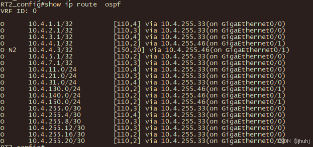
在RT2路由表中查看AC1重发布情况,可以看到N2就是在AC1中重发布的LOOPBACK3
SW3:
根据题目要求来
router ospf 2 vrf Office
 ospf router-id 10.4.3.2
 network 10.4.3.2/32 area 2
 network 10.4.110.0/24 area 2
 network 10.4.120.0/24 area 2
 network 10.4.255.28/30 area 2
!
router ipv6 ospf 2 vrf Office
 router-id 10.4.3.2
!
interface Vlan110
 ip vrf forwarding Office
 ipv6 address 2001:10:4:110::1/64
 ipv6 router ospf area 2 tag 2
 ip address 10.4.110.1 255.255.255.0
!
interface Vlan120
 ip vrf forwarding Office
 ipv6 address 2001:10:4:120::1/64
 ipv6 router ospf area 2 tag 2
 ip address 10.4.120.1 255.255.255.0
!
interface Vlan1015
 ip vrf forwarding Office
 ipv6 router ospf area 2 tag 2
 ip address 10.4.255.30 255.255.255.252
!
interface Loopback2
 ip vrf forwarding Office
 ipv6 address 2001:10:4:3::2/128
 ipv6 router ospf area 2 tag 2
 ip address 10.4.3.2 255.255.255.255
!
FW2:
ip vrouter "trust-vr"
  router ospf 2
    router-id 10.4.8.1
    network 10.4.8.1/32 area 2
    network 10.4.255.24/30 area 2
    network 10.4.255.28/30 area 2
  exit
  ipv6 router ospf 2
    router-id 10.4.8.1
  exit
interface ethernet0/1
  ipv6 ospf 2 area 2
exit
interface ethernet0/2
  ipv6 ospf 2 area 2
exit
interface loopback1
  ipv6 ospf 2 area 2
exit
RT1:

router ospf 2
 router-id 10.4.5.4
 network 10.4.5.4 255.255.255.255 area 2
 network 10.4.255.24 255.255.255.252 area 2
 redistribute ospf 1 将路由重发布到区域一
!
router ospf 1
 redistribute connect route-map RT1-FW2-IPv4
 redistribute ospf 2 route-map SW3-FW2-IPv4 调用route-map重发直连路由和区域二路由

router ospfv3 1
 router-id 10.4.5.1
 redistribute ospf 2 route-map SW3-FW2-IPv6

router ospfv3 2
 router-id 10.4.5.4
 redistribute ospf 1
!
interface GigaEthernet0/3
 ipv6 ospf 2 area 2
!
interface Loopback4
 ipv6 ospf 2 area 2
!

ip prefix-list RT1-FW2-IPv4 seq 5 permit 10.4.255.24/30
ip prefix-list SW3-FW2-IPv4 seq 5 permit 10.4.3.2/32
ip prefix-list SW3-FW2-IPv4 seq 10 permit 10.4.8.1/32
ip prefix-list SW3-FW2-IPv4 seq 15 permit 10.4.110.0/24
!
ipv6 prefix-list Sw3-FW2-IPv6 seq 5 permit 2001:10:4:3::2/128
ipv6 prefix-list Sw3-FW2-IPv6 seq 10 permit 2001:10:4:8::1/128
ipv6 prefix-list Sw3-FW2-IPv6 seq 15 permit 2001:10:4:110::/64
!
route-map SW3-FW2-IPv4 10 permit
 match ip address prefix-list SW3-FW2-IPv4
!
route-map SW3-FW2-IPv6 10 permit
 match ipv6 address prefix-list SW3-FW2-IPv6
!
route-map RT1-FW2-IPv4 10 permit
 match ip address RT1-Fw2-ipV4
!
创建相应前缀列表和调用route-map
RT1:
!
interface GigaEthernet0/1
 ipv6 ospf 1 area 0
 ipv6 ospf cost 100
!
Fw1:
interface ethernet0/2
  ip ospf cost 100
  ipv6 ospf cost 100
exit
!
最简单的方法是RT1与FW1的直连端口增加cost值实现优先选路
6.RT1 串行链路、RT2 串行链路、FW1、AC1 之间分别运行 RIP 和 RIPng 协议,分别发布 Loopback2 地址路由(FW1 的 RIPng 发布路由时用接 口名称)。RT1 配置 offset 值为 3 的路由策略,实现 RT1/S1/0- RT2/S1/1 为主链路,RT1/S1/1-RT2/S1/0 为备份链路,IPv4 的 ACL 名 称为 ACL-RIP-IPv4,IPv6 的 ACL 名称为 ACL-RIP-IPv6。RT1 的 S1/0 与 RT2 的 S1/1 之间采用 chap 双向认证,用户名为对端设备名称,密 码为 Key-1122。
RT1:
ip access-list standard ACL-RIP-IPv4
 permit any  sequence 10
!
ipv6 access-list ACL-RIP-IPv6
 permit ipv6 any any sequence 10
!
创建ipv4 v6访问控制列表,允许所有路由通过

router rip 1
 offset Serial1/1 in ACL-RIP-IPv4 3
 offset Serial1/1 out ACL-RIP-IPv4 3
!
router ripng 1
 offset Serial1/1 in ACL-RIP-IPv6 3
 offset Serial1/1 out ACL-RIP-IPv6 3
!
给1/1开销值增加3,达到从r1进走1/0(主),r2进走1/1(主)

aaa authentication ppp default local ppp认证方式为本地
username RT2 password 0 Key-1122  用户名对端
interface Serial1/0
 encapsulation ppp 封装ppp
 ppp authentication chap  验证方式为chap
 ppp chap hostname RT1   发送本段用户名
 ppp chap password 0 Key-1122  配置验证密码
 physical-layer speed 2048000  配置速率
 ipv6 enable
 ip rip 1 enable
 ipv6 rip 1 enable
!
interface Serial1/1
 encapsulation ppp
 ipv6 enable
 ip rip 1 enable
 ipv6 rip 1 enable
!
interface GigaEthernet0/1
 ipv6 enable
 ip rip 1 enable
 ipv6 rip 1 enable
//此端口配rip是为了跟FW1互通
!
interface Loopback2
 ip rip 1 enable
 ipv6 rip 1 enable
!
!
RT2:
aaa authentication ppp default local
username RT1 password 0 Key-1122
interface Serial1/0
 encapsulation ppp
 physical-layer speed 2048000
 ipv6 enable
 ip rip 1 enable
 ipv6 rip 1 enable
!
interface Serial1/1
 encapsulation ppp
 ppp authentication chap
 ppp chap hostname RT2
 ppp chap password 0 Key-1122
 physical-layer speed 2048000
 ipv6 enable
 ip rip 1 enable
 ipv6 rip 1 enable
!
interface GigaEthernet0/1
 ip rip 1 enable
 ipv6 rip 1 enable
//此端口配rip是为了跟AC1互通
!
interface Loopback2
 ip rip 1 enable
 ipv6 rip 1 enable
!
FW1:
ip vrouter "trust-vr"
  router rip
    network 10.4.7.2/32
    network 10.4.255.16/30
  exit
ipv6 router rip
    network loopback2
    network ethernet0/2
  exit

AC1:
router rip
 network 10.4.4.2/32
 network 10.4.255.44/30
!
router ipv6 rip
!
7.RT1 以太链路(物理速率为 2048000)、RT2 以太链路、FW1 之间运 行 ISIS 协议,instance 1,实现 Loopback3 之间 IPv4 互通和 IPv6 互通。RT1、RT2、FW1 的 NET 分别为 10.0000.0000.0005.00、 10.0000.0000.0006.00 、 10.0000.0000.0007.00 , 路 由 器 类 型 是 Level-2,互联接口网络类型为点到点。
RT1:
router isis 1
 is-type level-2
 net 10.0000.0000.0005.00
!
interface Loopback3
 ip router isis 1
 ipv6 router isis 1
 isis circuit-type level-2
!
interface GigaEthernet0/0
 ip router isis 1
 ipv6 router isis 1
 isis network point-to-point
 isis circuit-type level-2
!
interface GigaEthernet0/1
 ip router isis 1
 ipv6 router isis 1
 isis network point-to-point
 isis circuit-type level-2
!
RT2:
router isis 1
 is-type level-2
 net 10.0000.0000.0006.00
!
interface Loopback3
 ip router isis 1
 ipv6 router isis 1
 isis circuit-type level-2
!
interface GigaEthernet0/0
 ip router isis 1
 ipv6 router isis 1
 isis network point-to-point
 isis circuit-type level-2
!
FW1:
ip vrouter "trust-vr"
  router isis
    net 10.0000.0000.0007.00
    is-type level-2-only
  exit
interface loopback3
  isis enable
  isis circuit-type level-2-only
  isis ipv6 enable
exit
interface ethernet0/2
  isis enable
  isis circuit-type level-2-only
  isis network point-to-point
  isis ipv6 enable
exit
8.SW1、SW2、SW3、RT1、RT2 之间运行 BGP 协议,SW1、SW2、RT1 AS 号 65001、RT2 AS 号 65002、SW3 AS 号 65003。 SW1、SW2、SW3、RT1、RT2 之间通过 Loopback1 建立 IPv4 和 IPv6 BGP 邻居。
SW1:

router bgp 65001
 bgp router-id 10.4.1.1 //指定router-id
 neighbor 10.4.2.1 remote-as 65001  //建立邻居
 neighbor 10.4.2.1 update-source Loopback1 //指定更新源
 neighbor 10.4.2.1 next-hop-self //因为是lgp,指定下一跳,v6有本地链路不用指定
 neighbor 2001:10:4:2::1 remote-as 65001
 neighbor 2001:10:4:2::1 update-source Loopback1
 no neighbor 2001:10:4:2::1 activate //取消激活,ipv6需在家庭组里激活
 neighbor 10.4.3.1 remote-as 65003
 neighbor 10.4.3.1 ebgp-multihop 255 //因为as不一样,是egp,ipv6也要设
 neighbor 10.4.3.1 update-source Loopback1
 neighbor 2001:10:4:3::1 remote-as 65003
 neighbor 2001:10:4:3::1 ebgp-multihop 255
 neighbor 2001:10:4:3::1 update-source Loopback1
 no neighbor 2001:10:4:3::1 activate
 address-family ipv6 unicast
 neighbor 2001:10:4:2::1 activate
 neighbor 2001:10:4:3::1 activate
 exit-address-family
!
SW2:
router bgp 65001
 bgp router-id 10.4.2.1
 neighbor 10.4.1.1 remote-as 65001
 neighbor 10.4.1.1 update-source Loopback1
 neighbor 10.4.1.1 next-hop-self
 neighbor 2001:10:4:1::1 remote-as 65001
 neighbor 2001:10:4:1::1 update-source Loopback1
 no neighbor 2001:10:4:1::1 activate
 neighbor 10.4.3.1 remote-as 65003
 neighbor 10.4.3.1 ebgp-multihop 255
 neighbor 10.4.3.1 update-source Loopback1
 neighbor 2001:10:4:3::1 remote-as 65003
 neighbor 2001:10:4:3::1 ebgp-multihop 255
 neighbor 2001:10:4:3::1 update-source Loopback1
 no neighbor 2001:10:4:3::1 activate
 neighbor 10.4.5.1 remote-as 65001
 neighbor 10.4.5.1 update-source Loopback1
 neighbor 10.4.5.1 next-hop-self
 neighbor 2001:10:4:5::1 remote-as 65001
 neighbor 2001:10:4:5::1 update-source Loopback1
 no neighbor 2001:10:4:5::1 activate
 address-family ipv6 unicast
 neighbor 2001:10:4:1::1 activate
 neighbor 2001:10:4:3::1 activate
 neighbor 2001:10:4:5::1 activate
 exit-address-family
!
SW3:
router bgp 65003
 bgp router-id 10.4.3.1
 neighbor 10.4.1.1 remote-as 65001
 neighbor 10.4.1.1 ebgp-multihop 255
 neighbor 10.4.1.1 update-source Loopback1
 neighbor 2001:10:4:1::1 remote-as 65001
 neighbor 2001:10:4:1::1 ebgp-multihop 255
 neighbor 2001:10:4:1::1 update-source Loopback1
 no neighbor 2001:10:4:1::1 activate
 neighbor 10.4.2.1 remote-as 65001
 neighbor 10.4.2.1 ebgp-multihop 255
 neighbor 10.4.2.1 update-source Loopback1
 neighbor 2001:10:4:2::1 remote-as 65001
 neighbor 2001:10:4:2::1 ebgp-multihop 255
 neighbor 2001:10:4:2::1 update-source Loopback1
 no neighbor 2001:10:4:2::1 activate
 address-family ipv6 unicast
 neighbor 2001:10:4:1::1 activate
 neighbor 2001:10:4:2::1 activate
 exit-address-family
!
RT1:
router bgp 65001
 bgp router-id 10.4.5.1
 neighbor 10.4.2.1 remote-as 65001
 neighbor 10.4.2.1 update-source Loopback1
 neighbor 10.4.2.1 next-hop-self
 neighbor 2001:10:4:2::1 remote-as 65001
 neighbor 2001:10:4:2::1 update-source Loopback1
 no neighbor 2001:10:4:2::1 activate
 neighbor 10.4.6.1 remote-as 65002
 neighbor 10.4.6.1 ebgp-multihop 255
 neighbor 10.4.6.1 update-source Loopback1
 neighbor 2001:10:4:6::1 remote-as 65002
 neighbor 2001:10:4:6::1 ebgp-multihop 255
 neighbor 2001:10:4:6::1 update-source Loopback1
 no neighbor 2001:10:4:6::1 activate
 address-family ipv6 unicast
 neighbor 2001:10:4:2::1 activate
 neighbor 2001:10:4:6::1 activate
 exit-address-family
!
RT2:
router bgp 65002
 bgp router-id 10.4.6.1
 neighbor 10.4.5.1 remote-as 65001
 neighbor 10.4.5.1 ebgp-multihop 255
 neighbor 10.4.5.1 update-source Loopback1
 neighbor 2001:10:4:5::1 remote-as 65001
 neighbor 2001:10:4:5::1 ebgp-multihop 255
 neighbor 2001:10:4:5::1 update-source Loopback1
 no neighbor 2001:10:4:5::1 activate
 address-family ipv6 unicast
 neighbor 2001:10:4:5::1 activate
 exit-address-family
!
SW1 和 SW2 之间财务通过 Loopback2 建立 IPv4 和 IPv6 BGP 邻居。SW1 和SW2的Loopback2 IPv4互通采用静态路由;IPv6互通采用OSPFv3, process 2,area 2。
SW1:
配置LOOPBACK2静态路由互通:ip route vrf  Finance 10.4.2.2/32 10.4.255.2
//10.4.2.2/32 是目标地址SW2的loopback2地址,10.4.255.2是下一跳地址,对端vpn 1/0/24 的地址

router ipv6 ospf 2 vrf Finance
 router-id 10.4.1.2
!
配置v6互通,Loopback2和 vpn vlan 1024宣告ospf ipv6路由
interface Loopback2
 ip vrf forwarding Finance
 ipv6 address 2001:10:4:1::2/128
 ipv6 router ospf area 2 tag 2
 ip address 10.4.1.2 255.255.255.255
!
interface Vlan1024
 ip vrf forwarding Finance
 ipv6 router ospf area 2 tag 2
 ip address 10.4.255.1 255.255.255.2li
!
注意:添加实例后将清楚所有配置,这里vlan1024前面已经配过,Loopback2记得重新添加
 address-family ipv4 vrf Finance
 network 10.4.15.0/24
 neighbor 10.4.2.2 remote-as 65001
 neighbor 10.4.2.2 update-source Loopback2
 exit-address-family
 address-family ipv6 vrf Finance
 network 2001:10:4:15::/64
 neighbor 2001:10:4:2::2 remote-as 65001
 neighbor 2001:10:4:2::2 update-source Loopback2
 exit-address-family
!
与SW2通过Finance建立财务业务邻居关系


SW2:
ip route  vrf  Finance 10.4.1.2/32 10.4.255.1
interface Vlan1024
 ip vrf forwarding Finance
 ipv6 router ospf area 2 tag 2
 ip address 10.4.255.2 255.255.255.252
!
interface Loopback2
 ip vrf forwarding Finance
 ipv6 address 2001:10:4:2::2/128
 ipv6 router ospf area 2 tag 2
 ip address 10.4.2.2 255.255.255.255
!
 address-family ipv4 vrf Finance
 network 10.4.25.0/24
 neighbor 10.4.1.2 remote-as 65001
 neighbor 10.4.1.2 update-source Loopback1
 exit-address-family
 address-family ipv6 vrf Finance
 network 2001:10:4:25::/64
 neighbor 2001:10:4:1::2 remote-as 65001
 neighbor 2001:10:4:1::2 update-source Loopback1
 exit
验证:
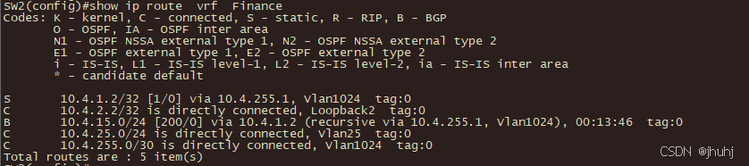
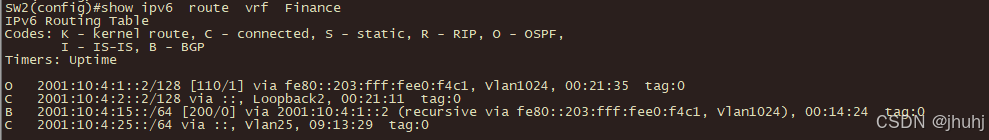 通过SW2的路由表可以看到,SW2已经与SW1建立了ipv4,v6的财务业务的bgp关系
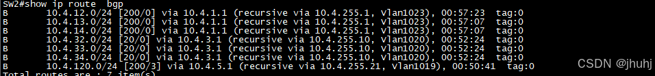
SW1:
router bgp 65001
network 10.4.12.0/24
network 10.4.13.0/24
network 10.4.14.0/24
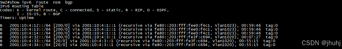
address-family ipv6 unicast
network 2001:10:4:12::/64
network 2001:10:4:13::/64
network 2001:10:4:14::/64
exit-address-family
SW2:
router bgp 65001
network 10.4.22.0/24
network 10.4.23.0/24
network 10.4.24.0/24
address-family ipv6 unicast
network 2001:10:4:22::/64
network 2001:10:4:23::/64
network 2001:10:4:24::/64
exit-address-family
SW3:
router bgp 65003
network 10.4.32.0/24
network 10.4.33.0/24
network 10.4.34.0/24
address-family ipv6 unicast
network 2001:10:4:32::/64
network 2001:10:4:33::/64
network 2001:10:4:34::/64
exit-address-family
RT1:
router bgp 65001
network 10.4.120.1/24
address-family ipv6 unicast
network 2001:10:4:120::1/64
exit-address-family
RT2:
router bgp 65002
network 10.4.150.1/24
address-family ipv6 unicast
network 2001:10:4:150::1/64
exit-address-family
SW3:
根据题目要求,要创8个前缀列表,分别是
1  SW1-SW2-YX-IPv4
2  SW1-SW2-YX-IPv6
3  SW3-YX-IPv4
4  SW3-YX-IPv6
5  SW1-SW2-FWRL-IPv4
6  SW1-SW2-FWRL-IPv6
7  SW3-FWRL-IPv4
8  SW3-FWRL-IPv6

第一个前缀列表SW1-SW2-YX-IPv4
ip prefix-list  SW1-SW2-YX-IPv4 permit  10.4.12.1/24
ip prefix-list  SW1-SW2-YX-IPv4 permit  10.4.22.1/24
第二个前缀列表SW1-SW2-YX-IPv6
ipv6 prefix-list  SW1-SW2-YX-IPv6 permit 2001:10:4:12::1/64
ipv6 prefix-list  SW1-SW2-YX-IPv6 permit 2001:10:4:22::1/64
第三个前缀列表SW3-YX-IPv4
ip prefix-list  SW3-IPv4 permit  10.4.32.1/24
第四个前缀列表SW3-YX-IPv6
ipv6 prefix-list  SW3-YX-IPv6 permit 2001:10:4:32::1/64
第五个前缀列表SW1-SW2-FWRL-IPv4
ip prefix-list SW1-SW2-FWRL-IPv4 permit 10.4.13.1/24
ip prefix-list SW1-SW2-FWRL-IPv4 permit 10.4.14.1/24
ip prefix-list SW1-SW2-FWRL-IPv4 permit 10.4.23.1/24
ip prefix-list SW1-SW2-FWRL-IPv4 permit 10.4.24.1/24
第六个前缀列表SW1-SW2-FWRL-IPv6
ipv6 prefix-list SW1-SW2-FWRL-IPv6 permit 2001:10:4:13::1/64
ipv6 prefix-list SW1-SW2-FWRL-IPv6 permit 2001:10:4:14::1/64
ipv6 prefix-list SW1-SW2-FWRL-IPv6 permit 2001:10:4:23::1/64
ipv6 prefix-list SW1-SW2-FWRL-IPv6 permit 2001:10:4:24::1/64
第七个前缀列表SW3-FWRL-IPv4
ip prefix-list SW3-FWRL-IPv4 permit 10.4.33.1/24
ip prefix-list SW3-FWRL-IPv4 permit 10.4.34.1/24
第八个前缀列表SW3-FWRL-IPv6
ipv6 prefix-list  SW3-FWRL-IPv6 permit 2001:10:4:33::1/64
ipv6 prefix-list  SW3-FWRL-IPv6 permit 2001:10:4:34::1/64

route-map调用第一个前缀列表SW1-SW2-YX-IPv4

route-map SW1-SW2-YX-IPv4 permit 10
 match ip address prefix-list SW1-SW2-YX-IPv4
 set as-path prepend 65000
新增as,便于选路
 set ip next-hop 10.4.1.1
指定营销流量都优先往SW1走
!
route-map SW1-SW2-YX-IPv4 permit 20
这里是为了备份
!

route-map调用第二个前缀列表SW1-SW2-YX-IPv6

route-map SW1-SW2-YX-IPv6 permit 10
 match ipv6 address prefix-list SW1-SW2-YX-IPv6
 set as-path prepend 65000
 set ipv6 next-hop 2001:10:4:1::1
!
route-map SW1-SW2-YX-IPv6 permit 20
!

route-map调用第三个前缀列表SW3-YX-IPv4

route-map SW3-YX-IPv4 permit 10
 match ip address prefix-list SW3-YX-IPv4
 set as-path prepend 65000
 set ip next-hop 10.4.1.1
!
route-map SW3-YX-IPv4 permit 20
!

route-map调用第四个前缀列表SW3-YX-IPv6

route-map SW3-YX-IPv6 permit 10
 match ipv6 address prefix-list SW3-YX-IPv6
 set as-path prepend 65000
 set ipv6 next-hop 2001:10:4:1::1
!
route-map SW3-YX-IPv6 permit 20
!

route-map调用第五个前缀列表SW1-SW2-FWRL-IPv4

route-map SW1-SW2-FWRL-IPv4 permit 10
 match ip address prefix-list SW1-SW2-FWRL-IPv4
 set as-path prepend 65000
 set ip next-hop 10.4.2.1
!
route-map SW1-SW2-FWRL-IPv4 permit 20
!

route-map调用第六个前缀列表SW1-SW2-FWRL-IPv6

route-map SW1-SW2-FWRL-IPv6 permit 10
 match ipv6 address prefix-list SW1-SW2-FWRL-IPv6
 set as-path prepend 65000
 set ipv6 next-hop 2001:10:4:2::1
!
route-map SW1-SW2-FWRL-IPv6 permit 20
!


route-map调用第七个前缀列表SW3-FWRL-IPv4

route-map SW3-FWRL-IPv4 permit 10
 match ip address prefix-list SW3-FWRL-IPv4
 set as-path prepend 65000
 set ip next-hop 10.4.2.1
!
route-map SW3-FWRL-IPv4 permit 20
!

route-map调用第八个前缀列表SW3-FWRL-IPv6

route-map SW3-FWRL-IPv6 permit 10
 match ipv6 address prefix-list SW3-FWRL-IPv6
 set as-path prepend 65000
 set ipv6 next-hop 2001:10:4:2::1
!
route-map SW3-FWRL-IPv6 permit 20
!


router bgp  65003
neighbor 10.4.1.1 route-map  SW1-SW2-FWRL-IPv4 in
FWRL从SW1进SW3的流量优先从SW2-SW3走
neighbor 10.4.1.1 route-map  SW3-FWRL-IPv4 out
FWRL从SW3出的流量优先从Sw3-sw2走
neighbor 10.4.2.1 route-map  SW1-SW2-YX-IPv4 in
YX从SW2进SW3的流量优先从SW1-SW3走
neighbor 10.4.2.1 route-map  SW3-YX-IPv4 out
YX从SW3出的流量优先从SW3-SW1走
address-family  ipv6
neighbor  2001:10:4:1::1 route-map  SW1-SW2-FWRL-IPv6 in
neighbor  2001:10:4:1::1 route-map  SW3-FWRL-IPv6 out
neighbor  2001:10:4:2::1 route-map  SW1-SW2-YX-IPv6 in
neighbor  2001:10:4:2::1 route-map  SW3-YX-IPv6 out
验证:
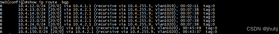
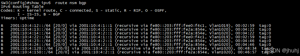
可以看到,SW1,SW2的ipv4,v6营销都从vlan1019口进来 ,FWRL从vlan1020进来,验证成功
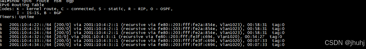

可以看到从相应vlan出,验证成功
9.利用 BGP MPLS VPN 技术,RT1 与 RT2 以太链路间运行多协议标签 交换、标签分发协议。RT1 与 RT2 间创建财务 VPN 实例,名称为 Finance, RT1 的 RD 值为 1:1,export rt 值为 1:2,import rt 值为 2:1;RT2 的 RD 值为 2:2。通过两端 Loopback1 建立 VPN 邻居,分别实现两端 Loopback5 IPv4 互通和 IPv6 互通。
RT1:
mpls ip
全局启用
mpls ldp router-id 10.4.5.1
配置Ldp路由标识

interface GigaEthernet0/0
 mpls ip
接口启用
 mpls ldp enable
配置Ldp接口路由标识
!
ip vrf Finance
 rd 1:1
 route-target export 1:2
(给出去的流量打上标签)
因为1:2是出口标签,所以RT2的import为1:2,接受RT1发出的的标签
 route-target import 2:1
(接受进入的标签流量)
因为2:1是进入标签,所以RT2的export为2:1,发出2:1标签是RT1接收
!
ipv6 vrf Finance
 rd 1:1
 route-target import 2:1
 route-target export 1:2
!
配置ipv4与ipv6实例

interface Loopback5
 ip vrf forwarding Finance
 ip address 10.4.5.5 255.255.255.255
 ipv6 enable
 ipv6 address 2001:10:4:5::5/128
 ipv6 vrf forwarding Finance
!
注意:加入ipv4 vrf后会清空此接口配置,再重新添加原来的配置即可

 address-family vpnv4
 neighbor 10.4.6.1 activate
// 激活ldp路由标识的邻居
 neighbor 10.4.6.1 send-community both
//向邻居发送扩展的社区属性
 exit-address-family
 address-family vpnv6
 neighbor 2001:10:4:6::1 activate
 neighbor 2001:10:4:6::1 send-community both
 exit-address-family

 address-family ipv4 vrf Finance
 network 10.4.5.5/32
//宣告网段
 exit-address-family
 address-family ipv6 vrf Finance
 network 2001:10:4:5::5/128
 exit-address-family

RT2:
mpls ip
mpls ldp router-id 10.4.6.1
interface GigaEthernet0/0
 mpls ip
 mpls ldp enable
!
ip vrf Finance
 rd 2:2
 route-target export 2:1
 route-target import 1:2

!
ipv6 vrf Finance
 rd 2:2
 route-target import 1:2
 route-target export 2:1
!
interface Loopback5
 ip vrf forwarding Finance
 ip address 10.4.6.5 255.255.255.255
 ipv6 enable
 ipv6 address 2001:10:4:6::5/128
 ipv6 vrf forwarding Finance
!
 address-family vpnv4
 neighbor 10.4.5.1 activate
 neighbor 10.4.5.1 send-community both
 exit-address-family
 address-family vpnv6
 neighbor 2001:10:4:5::1 activate
 neighbor 2001:10:4:5::1 send-community both
 exit-address-family

 address-family ipv4 vrf Finance
 network 10.4.6.5/32
 exit-address-family
 address-family ipv6 vrf Finance
 network 2001:10:4:6::5/128
 exit-address-family
验证:
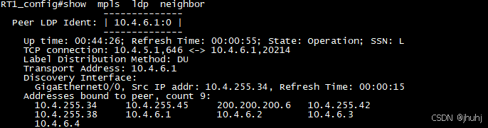 可以看到已经通过LOOPBACK1建立了vpn邻居
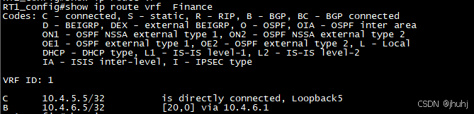
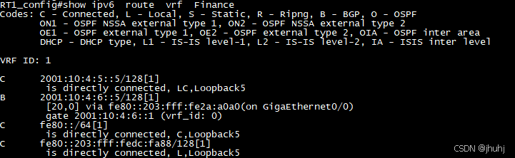
可以看到loopback5已经在bgp vrf v4和v6中互通
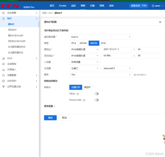
10.RT2 配置 IPv4 NAT,ACL 名称为 ACL-NAT,实现 AC1 IPv4 产品用 RT2 外网接口 IPv4 地址访问 Internet。RT2 配置 NAT64,ACL 名称为 ACL-NAT64,实现 AC1 IPv6 产品用 RT2 外网接口 IPv4 地址访问 Internet,IPv4 地址转 IPv6 地址前缀为 64:ff9b::/96。
RT2:
ip route default 200.200.200.5
!
//设置默认路由将所有未明确指定目的地的流量(即默认流量)转发到指定的下一跳地址,以便能成功访问外网
ip access-list standard ACL-NAT
 permit 10.4.140.1 255.255.255.0 sequence 10
 //约定NAT4转换规则
!
ipv6 access-list ACL-NAT64
 permit ipv6 2001:10:4:140::/64 64:FF9B::/96 sequence 10
 //约定nat64 转换规则
!
ip nat inside source list ACL-NAT interface GigaEthernet0/2
//IPv4转换规则
ipv6 nat v6v4 source list ACL-NAT64 interface GigaEthernet0/2
//IPv6转换规则
ipv6 nat prefix 64:FF9B::/96 v4-mapped ACL-NAT64
//ipv4地址转ipv6地址前缀

interface GigaEthernet0/1
 ip nat inside
//对内接口
 ipv6 nat
//接口启动ipv6转换

!
interface GigaEthernet0/2
 ip nat outside
//对外接口
 ipv6 nat
!

![]()
AC1上用产品ping外网成功,RT2上显示转换命中成功

AC1上用ipv6产品ping外网成功,ipv6转换成功
(四)无线部署
1.AC1 与 AP1 相连接口只允许 Vlan140 和 Vlan150 通过。AC1 Loopback1 IPv4 和 IPv6 地址分别作为 AC1 的 IPv4 和 IPv6 管理地址。AP 二层自动注册,AP 采用 MAC 地址认证。配置 2 个 ssid,分别为 SKILLS-2.4G 和 SKILLS-5G。SKILLS-2.4G 对应 Vlan140,用 Network140 和 radio1(profile 1, mode n-only-g),用户接入无线网络时需要采用基于 WPA-personal 加密方式,密码为 Key-1122,用第一个可用 VAP 发送 2.4G 信号。SKILLS-5G 对应 Vlan150,用 Network 150和 radio2(profile 1, mode n-only-a),不需要认证,隐藏 ssid,SKILLS-5G 用倒数第一个可用 VAP 发送 5G 信号。
AC1:
 wireless
进入ap配置模式
 enable
启动模式
 no auto-ip-assign
取消动态分配
 ap authentication mac
开启mac认证模式
 ap database 00-03-0f-d9-cd-c0
配置mac

 discovery ipv6-list 2001:10:4:130::1
 discovery ip-list 10.4.130.1
//ap上线不了可以敲这个三层发现

 discovery vlan-list 130
ap二层自动注册

 static-ip  10.4.4.1
 static-ipv6  2001:10:4:4::1
配置ac管理地址

 network 140
  security mode wpa-personal
 认证方式为个人认证
  ssid SKILLS-2.4G
配置方式为SSID
  vlan 140
  wpa key encrypted 02ee7ad3f247f1845d18a798ec17abd797a22f75a0f6cb5e2c2804706125ef61c2140fd7205150769d49a0b7b9f374be1975498ce48aa688ad20960fef0af8ba
!
配置密码
 network 150
  hide-ssid
隐藏ssid

  ssid SKILLS-5G
  vlan 150

  security  mode  none
  配置无认证
!
 ap profile 1
  radio 1
   mode n-only-g
   vap 0
//vap 0 默认开启,可以不用配置enable启动
    network 140
!
  radio 2
   mode n-only-a
   vap 15
   enable
   network 150
!
验证:
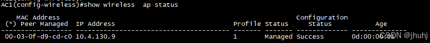
可以看到ap已经上线
(五)安全维护(本题共 5 分)
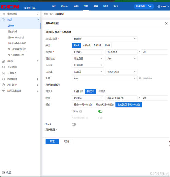
1.FW1 配置 IPv4 NAT,id 为 1,实现集团产品 1 段 IPv4 访问 Internet IPv4,转换 ip/mask 为 200.200.200.16/28,保证每一个源 ip 产生 的所有会话将被映射到同一个固定的 IP 地址。
2.FW1 配置 NAT64,id 为 2,实现集团产品 1 段 IPv6 访问 Internet IPv4,转换为出接口 IP,IPv4 转 IPv6 地址前缀为 64:ff9b::/96。
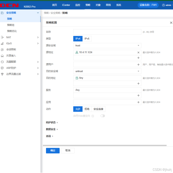
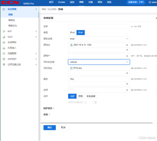
3.FW1 和 FW2 策略默认动作为拒绝,FW1 允许 集团产品 1 段 IPv4 和 IPv6 访问 Internet 任意服务。
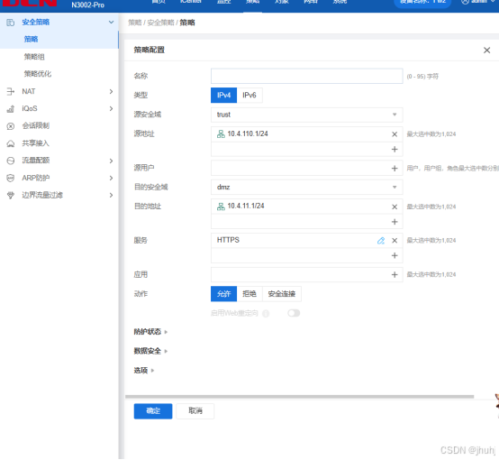
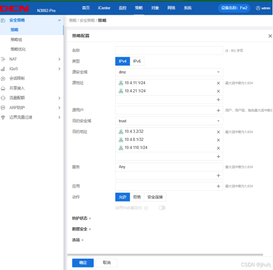
4.FW2 允许办事处产品 IPv4 访问集团产品 1 段 https 服务,允许集 团产品 1 段和产品 2 段访问 SW3 模拟办事处 Loopback2 IPv4、FW2 Loopback1 IPv4、办事处产品 IPv4。
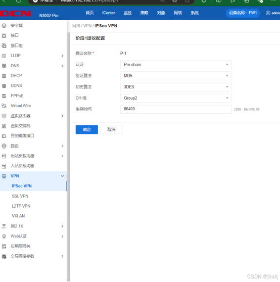
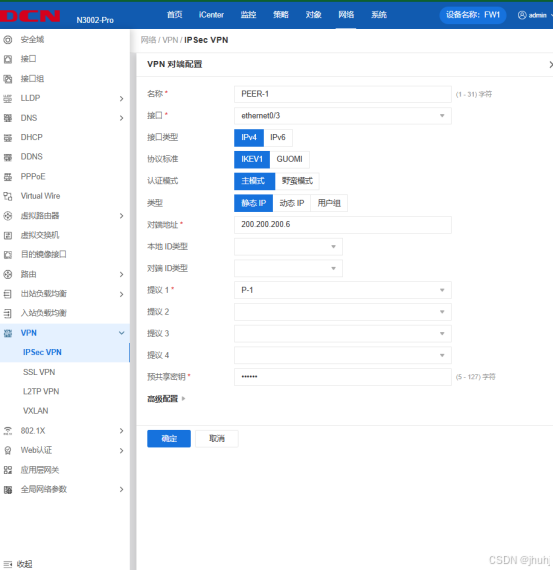
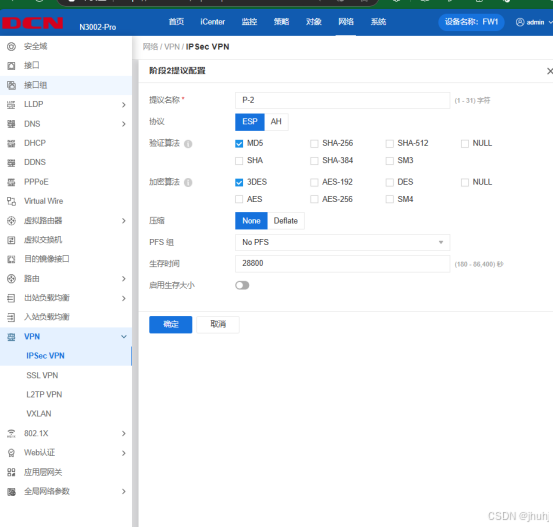
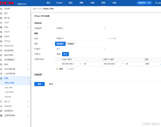
5.FW1 与 RT2 之间用 Internet 互联地址建立 GRE Over IPSec VPN, 实现 Loopback4 之间的加密访问。RT2 的 ACL 名称为 ACL-VPN, transform-set 名称为 SET-1,crypto map 名称为 MAP-1。FW1 的 isakmp proposal 名称为 P-1,isakmp peer 名称为 PEER-1,ipsec proposal 名称为 P-2,tunnel ipsec 名称为 IPSEC-1,tunnel gre 名 称为 GRE-1。
SW3:
ip route  vrf  Office 0.0.0.0/0 200.200.200.6
ip route  vrf  Office 0.0.0.0/0 200.200.200.2
//转发实例达到互联互通
RT1:
因为前面nat转换配过默认路由,所以可以不用配默认路由
ip route  10.4.7.4 255.255.255.255 tunnel  4
//让loopback4通过隧道加密访问
interface Tunnel4
 tunnel source 200.200.200.6
 tunnel destination 200.200.200.2
//配置隧道端口源ip与目的ip地址


crypto isakmp policy 1
 authentication pre-share
 encryption 3des
 group 2
 hash md5
 lifetime 86400
!
//配置提议一,与FW1对应

crypto isakmp key 0 123456 address 200.200.200.2 255.255.255.255
//配置协商

crypto ipsec transform-set SET-1 esp-3des esp-md5-hmac
!
//配置提议二,与FW1对应

ip access-list extended ACL-VPN
 permit gre 200.200.200.6 255.255.255.252 200.200.200.2 255.255.255.252 sequence 10
!
配置ACL-VPN,使特定流量通过

crypto map MAP-1 1 ipsec-isakmp
 match address ACL-VPN
 set peer 200.200.200.2
 set transform-set SET-1
!
//创建加密图

interface GigaEthernet0/2
 crypto map MAP-1
!
//调用加密图

FW1:
 ip route  0.0.0.0/0 200.200.200.1
使路由到达et1/0/17,达到FW1与RT2的访问
ip route  10.4.6.4/32 tunnel4
//让loopback4通过隧道加密访问
tunnel gre "GRE-1"
  source 200.200.200.2
  destination 200.200.200.6
  interface ethernet0/3
  next-tunnel ipsec IPSEC-1
exit
interface tunnel4
  tunnel gre "GRE-1" gw 10.4.255.50
//调用gre,gw为对端隧道ip
exit
验证:
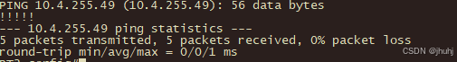
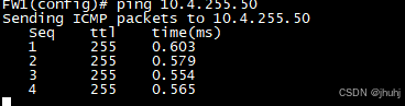
验证成功!


 7452
7452

 被折叠的 条评论
为什么被折叠?
被折叠的 条评论
为什么被折叠?
 到【灌水乐园】发言


