


目录
init stack and jump to sbl1_main_ctl
1,xbl.elf及xbl_config.elf的作用及组成
4,8155的reset status & boot_fail_count 及启动温度
8,进入Embedded Boot Loader (EBL)的方法
9,待分析问题1:tz是如何加载运行hyp_a分区的镜像的?
XBL源码下载
通常release note文档会有每种软件包的下载链接,其中也包含了XBL源码:
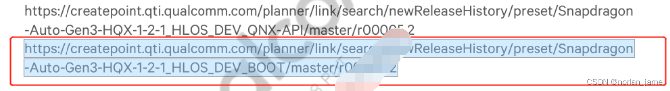
下载软件包,解压之后,可以看到XBL的源码目录:boot_8155
XBL代码路径
进入目录: boot_8155/boot_images/QcomPkg
root@ubuntu:~/workspace/8155/boot_8155/boot_images/QcomPkg$ ls
aliasconfig.json  buildex.py      delcommonts.pyc  Drivers  Library  QcomModulePkg  QcomTestPkg   SDMPkg    spy_buildex.py        Tools    XBLLoader         XBLRamDump
Application       delcommonts.py  Docs             Include  Logo     QcomPkg.dec    QcomToolsPkg  Settings  toolchainconfig.json  XBLCore  XBLLoaderApi.dec
XBL编译方法
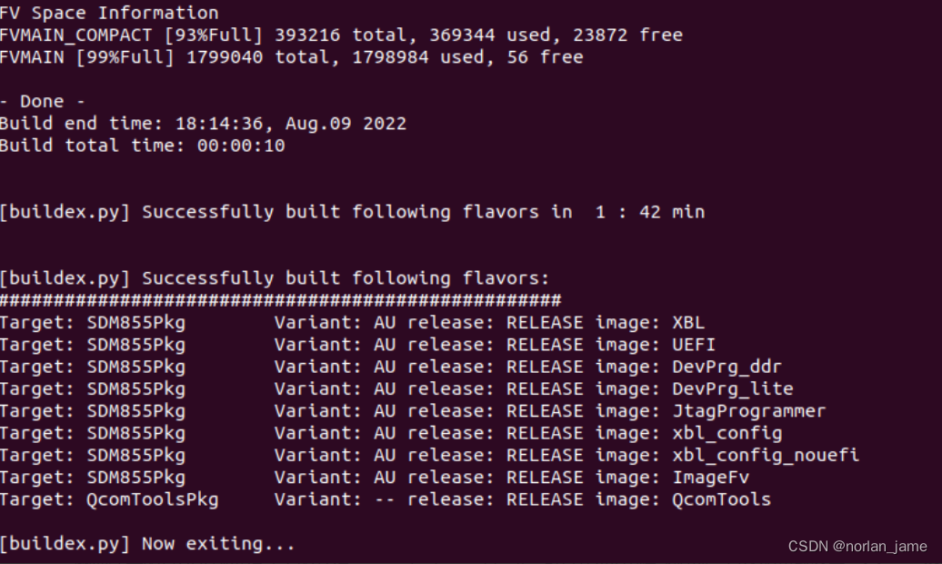
进入目录: boot_8155/boot_images/QcomPkg,执行编译指令:
python buildex.py --variant AU -r RELEASE -t SDM855Pkg,QcomToolsPkg
编译成功:
清除编译:
python buildex.py --variant AU -r RELEASE -t SDM855Pkg,QcomToolsPkg --build_flags=cleanall
编译输出文件:
QcomPkg/SDMPkg/855/Bin/AU/RELEASE/xbl.elf
QcomPkg/SDMPkg/855/Bin/AU/RELEASE/xbl_config.elf
需要注意的是QFIL刷机模式下的文件:prog_firehose_ddr.elf,也是从XBL中编译得到,具体源码路径为:Library/DevPrgLib/devprg_firehose.c
XBL编译过程
XBL本质上是UEFI(Unified Extensible Firmware Interface),所以在编译的时候遵循的是UEFI的编译方法和规则。
XBL编译指令解析过程
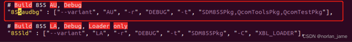
编译xbl是通过编译指令: python buildex.py --variant AU -r RELEASE -t SDM855Pkg,QcomToolsPkg
指令的含义是:编译AU变种的release版本,编译的包包括 SDM855Pkg,QcomToolsPkg
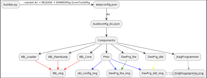
python脚本buildex.py会根据参数从aliasconfig.json文件中解析出要编译的模块。比如我们的参数会对应下面的模块:
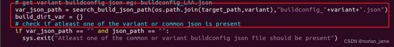
然后buildex.py通过下面接口找到对应的buildconfig(这个文件用来表明,整个编译过程会编译那些模块),这个文件在当前的参数下为buildconfig_AU.json
 buildconfig_AU.json
buildconfig_AU.json部分内容如下:
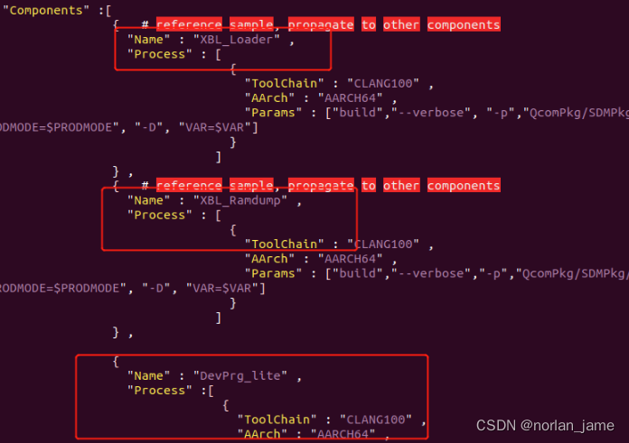
buildconfig_AU.json中由两大部分组成:
Components: 可以简单的理解为“组件”/“模块”,每个节点代表一个组件/模块.比如下面是名为XBL_Loader的模块:
{   # reference sample, propagate to other components
  "Name" : "XBL_Loader" ,
  "Process" : [
                {
                  "ToolChain" : "CLANG100" ,
                  "AArch" : "AARCH64" ,
                  "Params" : ["build","--verbose", "-p","QcomPkg/SDMPkg/855/Common/Loader.dsc","-j", "QcomPkg/SDMPkg/855/$VAR/build_Loader.log","-w","-a","AARCH64","-b","$REL","-D","PRODMODE=$PRODMODE", "-D", "VAR=$VAR"]
                }
              ]
} ,CreateImages:用于通过组合Components来编译成最终的镜像文件,CreateImages中的每个节点都表示最终需要编译生产的镜像,比如下面是xbl.elf镜像的节点描述: 通过"XBL_Loader", "XBL_Core", "XBL_Ramdump" 三个模块生产最终的xbl.elf镜像.
{
  "Name" : "XBL" ,    # Just cosmetic, readable field for reference, ignored by tool/script
  "Process" : [
                {
                  "ToolChain" : "Merge" ,
                  "SecImage" : "$BUILDROOT/QcomPkg/SDMPkg/855/Library/XBL_SEC/AU/xbl_sec.mbn",
                  "Components" : ["XBL_Loader", "XBL_Core", "XBL_Ramdump"],
                  "Params" : ["-f","$FIRSTDLL", "-s", "$SECONDDLL", "-x","$XBLSEC", "-a", "64", "-b", "64", "-d", "64", "-o", "$BUILDROOT/Build/SDM855_Loader/$REL_$COMPILER/$AARCH/xbl.elf"]
                },
                {
                  "ToolChain" : "Copy",
                  "Createfolders" : ["$BUILDROOT/$TARGETROOT/Bin/$VAR/$REL/unsigned"],
                  "Params" : ["$BUILDROOT/Build/SDM855_Loader/$REL_$COMPILER/$AARCH/xbl.elf","$BUILDROOT/$TARGETROOT/Bin/$VAR/$REL/unsigned"]
                },
                {
                  "ToolChain" : "Sign" ,
                  "Createfolders" : ["$BUILDROOT/$TARGETROOT/Bin/$VAR/$REL/sign"],
                  "Params" : ["-t","$BUILDROOT/$TARGETROOT/Bin/$VAR/$REL",
                              "-i", "$BUILDROOT/Build/SDM855_Loader/$REL_$COMPILER/$AARCH/xbl.elf",
                              "-g", "sbl1",
                              "--config","$BUILDROOT/QcomPkg/Tools/sectools/config/integration/secimagev3.xml" ,
                              "--hash_table_algo", "sha384",
                              "--soc_hw_version","0x60030000",
                              "--soc_vers","0x6003"]
                },
                {
                  "ToolChain" : "Copy",
                  "Params" : ["$BUILDROOT/$TARGETROOT/Bin/$VAR/$REL/sign/default/sbl1/xbl.elf","$BUILDROOT/$TARGETROOT/Bin/$VAR/$REL"]
                }
              ]
} ,
对于xbl.elf这镜像来说,"XBL_Loader", "XBL_Ramdump"这两个模块会先被编译,最后通过XBL_Core来组成最后镜像.关于更多uefi编译细节可以参考<UEFI原理与编程>
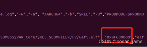
需要注意的是,这个文件也指定了镜像load到内存的地址位置,比如xbl_core的地址0x9FC00000.
回到"XBL_Loader", "XBL_Ramdump" XBL_Core 这几个模块的编译过程,所有的编译细节可以通过buildconfig_AU.json中提到的log文件得到,比如:
 SDMPkg/855/AU/build_Loader.log这个log文件记录了编译整个模块的编译过程(也就是我们在编译xbl时终端输出的内容):

DSC文件
前面我们提到,编译过程中我们会用到dsc文件,这个文件类似于Makefile,当编译XBL_Loader时,对应的文件:QcomPkg/SDMPkg/855/Common/Loader.dsc, 这个文件表明了编译XBL_Loader本身所需要的模块的inf文件,以及代码中会引用到的模块(由.inf文件表示)
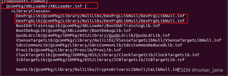
从文件XBLLoader/XBLLoader.inf中可以找到xbl.elf源码的真正入口:
XBL编译流程总结
XBL代码流程分析
8155-XBL boot全景图

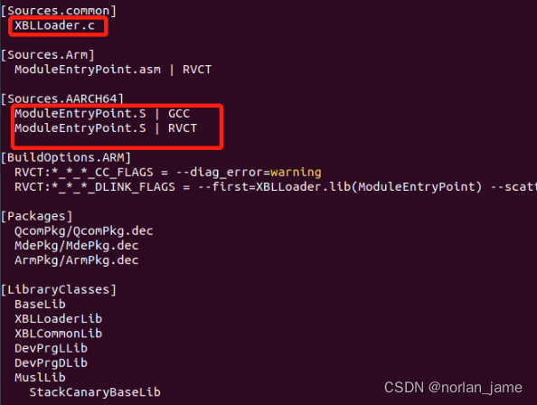
ModuleEntryPoint.S
根据上面提到的QcomPkg/XBLLoader/XBLLoader.inf文件,xbl.elf的源码入口有两个文件:
XBLLoader.c
ModuleEntryPoint.S
但是XBLLoader.c并没有真实的代码入口,而只是一个空的文件,真正的代码入口在ModuleEntryPoint.S中.
_ModuleEntryPoint:
#ifdef FEATURE_START_EL3
  /* Get current EL in x4 */
  EL1_OR_EL2_OR_EL3(x4)
1:
    /* x0 should contain PBL shared data pointer */
BootBackupX0:
    mov x19, x0

BootDisableInterrupts:
    /* First ensure all interrupts are disabled */
    bl ASM_PFX(ArmDisableInterrupts)

BootDisableCacheMmu:
    /* Ensure that the MMU and caches are off */
    bl ASM_PFX(ArmDisableCachesAndMmu)

BootInvalInstructionCache:
    /* Invalidate Instruction Cache and TLB */
    bl ASM_PFX(ArmInvalidateInstructionCache)

BootInvalidateTlb:
    bl ASM_PFX(ArmInvalidateTlb)

BootRestoreX0:
    mov x0, x19
#endif

BootBranchLoaderEntry:
    b sbl1_entry
整个ModuleEntryPoint.S的核心部分的源码如上所示,大致可以分为三个部分:
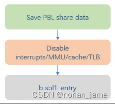
在最开始的部分,ModuleEntryPoint.S会立即把指向PBL share data的指针从x0寄存器保存到x19寄存器,然后进行一些列的操作,比如关闭interrupts/MMU/TLB. 为什么一定要关闭这些模块/功能,主要有几点原因:
1,在boot的这个阶段,最主要的目的是尽快同时安全的把数据搬运到SOC的ram中运行,主要的工作是进行一些非常基础的硬件初始化,比如ddr
2,interrupts/mmu/cache等这些模块在这个阶段并不会被用到
3,这些模块如果enable,有可能会影响到boot正常流程导致boot失败,比如interrupt
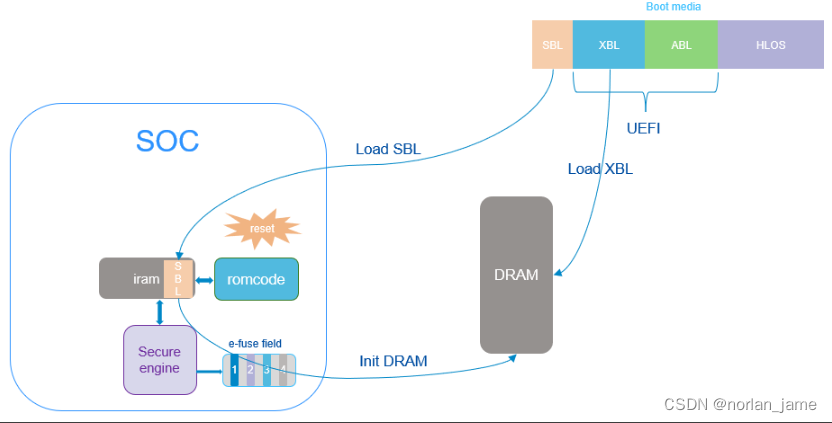
xbl的最初的代码是会被load到SOC内部的ram中运行,这里称为SBL:
sbl1_Aarch64.s
sbl1_entry源码位于sbl1_Aarch64.s中,其源码如下:
sbl1_entry:
  // Preserve parameter from PBL in x7
  MOV x7, x0
  MOV X0, #0
  MOV SP, X0

  //Disable cache, MMU, and add alignment checks
  DSB SY
  ISB SY

  TLBI VMALLE1  //TLB invalidate
  IC IALLU      //Invalidate cache to PoU

  DSB SY
  ISB SY

  MRS X0, SCTLR_EL1
  AND X0,X0, #~(M_BIT)
  AND X0,X0, #~(C_BIT)
  // ORR X0,X0, #(A_BIT) //TODO: Enable after CPR fixes alignment fault
  ORR X0,X0, #(SA_BIT)
  MSR SCTLR_EL1, X0

  DSB SY
  ISB SY

  // Configure SBL1 vector table base for EL1 VBARs (XBL context)
  // -------------------------------
  LDR x0, =sbl1_vector_table
  MSR VBAR_EL1, x0

  // Check for pending aborts
  // -------------------------------
  MRS X0, ISR_EL1
  AND X0, X0, #ISR_EL1_A_BIT
  CBNZ X0, boot_loop_here

  // Enable external aborts
  // -------------------------------
  MSR DAIFClr, #INT_A_BIT
  isb

  // retrieve stack-base
  // -------------------------------
  MOV x0,  SBL1_STACK_BASE & 0xffff
  MOVK x0, SBL1_STACK_BASE >> 16, LSL #16

  // configure stack for SBL (EL1)
  // -------------------------------
  MOV SP, x0

  // Zero init stack region
  // -------------------------------
  MOV  x0, SCL_SBL1_STACK_BASE & 0xffff
  MOVK x0, SCL_SBL1_STACK_BASE >> 16, LSL #16

  MOV  x1, SCL_SBL1_STACK_SIZE & 0xffff
  MOVK x1, SCL_SBL1_STACK_SIZE >> 16, LSL #16

  // size expected to be 16 (0x10) byte aligned
  BIC  x1, x1, #0xF
  MOV  x2, #0             // used as counter

write_16bytes_loop:
  stp xzr,xzr,[x0], #0x10
  add     x2, x2, #0x10   // increment by 16 bytes
  cmp     x1, x2
  b.ne write_16bytes_loop

sbl1_entry_init_stack:
  // -------------------------------
  // add more assembly init code here for entering sbl1_main_ctl
  //
  // restore PBL parameter and enter sbl1_main_ctl
  // -------------------------------
  MOV w0, w7
  BL sbl1_main_ctl

  // For safety
  BL boot_loop_here  // never returns
这里将会详细分析每段代码:
保存PBL share data
// Preserve parameter from PBL in x7
MOV x7, x0    //通过MOV指令把PBL share data 指针保存到x7寄存器中
MOV X0, #0    //x0寄存器赋值为0
MOV SP, X0
Disable MMU/Cache
//Disable cache, MMU, and add alignment checks
DSB SY
ISB SY

TLBI VMALLE1  //TLB invalidate
IC IALLU      //Invalidate cache to PoU

DSB SY
ISB SY

MRS X0, SCTLR_EL1
AND X0,X0, #~(M_BIT)
AND X0,X0, #~(C_BIT)
// ORR X0,X0, #(A_BIT) //TODO: Enable after CPR fixes alignment fault
ORR X0,X0, #(SA_BIT)
MSR SCTLR_EL1, X0

DSB SY
ISB SY
DSB/ISB指令的作用参考如下: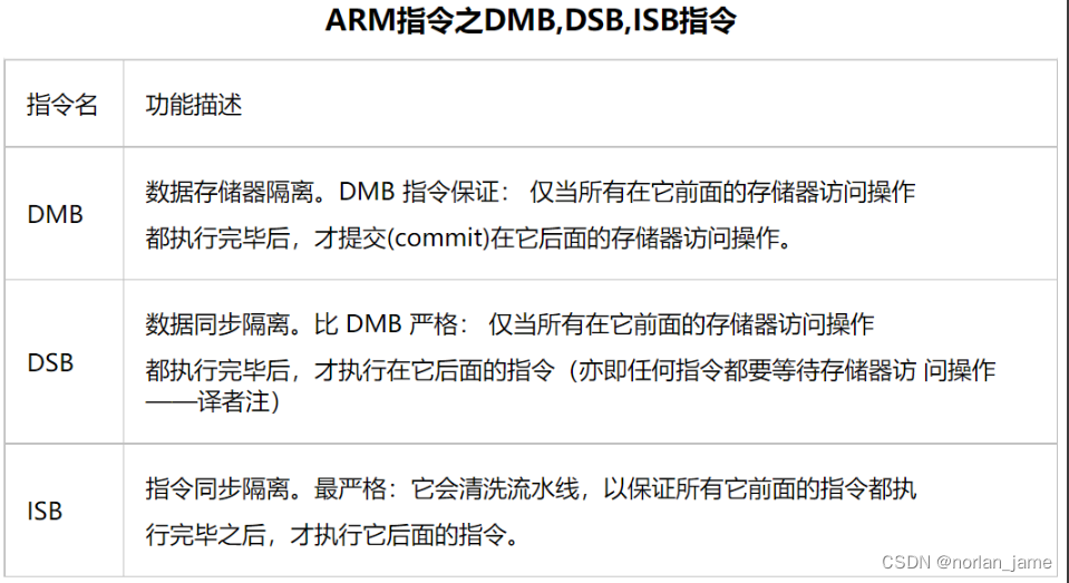
- 上面这段代码多次调用了DSB SY & ISB SY 目的是为了保证前后指令都能干净独立的执行完成.
- TLBI VMALLE1 & IC IALLU是arm64架构上的特殊指令
- TLBI VMALLE1 表示的是: TLB invalidation, VMALLE1 表示的是:vm-all-e1
- IC IALLU作用是设置instruction cache中的所有的cache line是无效的,直到PoU
- SCTLR_EL1为system control reigster el1,用于控制整个系统,对于这个寄存器更多细节可以参考:SCTLR_EL1_System_Control_Register_EL1
- 这里先把SCTLR_EL1读取到x0寄存器中,然后对x0寄存器的M_BIT&C_BIT、SA_BIT进行操作,再回写到SCTLR_EL1
- 更多细节可以参考wowotech cpu_setup
Configure vector table
通过下面代码配置异常向量表
// Configure SBL1 vector table base for EL1 VBARs (XBL context)
// -------------------------------
LDR x0, =sbl1_vector_table
MSR VBAR_EL1, x0
// Check for pending aborts
// -------------------------------
MRS X0, ISR_EL1
AND X0, X0, #ISR_EL1_A_BIT
CBNZ X0, boot_loop_here
代码比较简单,sbl1_vector_table 里面存储了异常向量表指针,这个指针最终赋值给了寄存器VBAR_EL1
关于VBAR_EL1的信息可以参考:VBAR_EL1
异常向量表相关的概念可以参考:什么是异常向量表
最后检查ISR_EL1寄存器的ISR_EL1_A_BIT来检查是否有pending的异常,如果有则进入死循环
Enable external aborts
这里通过DAIFClr直接配置PSTATE寄存器中的A bit为1,DAIF寄存器表示PSTATE寄存器中的{D,A,I,F}字段.
// Enable external aborts
// -------------------------------
MSR DAIFClr, #INT_A_BIT
isb
init stack and jump to sbl1_main_ctl
这段代码如下:
  // retrieve stack-base
  // -------------------------------
  MOV x0,  SBL1_STACK_BASE & 0xffff
  MOVK x0, SBL1_STACK_BASE >> 16, LSL #16

  // configure stack for SBL (EL1)
  // -------------------------------
  MOV SP, x0

  // Zero init stack region
  // -------------------------------
  MOV  x0, SCL_SBL1_STACK_BASE & 0xffff
  MOVK x0, SCL_SBL1_STACK_BASE >> 16, LSL #16

  MOV  x1, SCL_SBL1_STACK_SIZE & 0xffff
  MOVK x1, SCL_SBL1_STACK_SIZE >> 16, LSL #16

  // size expected to be 16 (0x10) byte aligned
  BIC  x1, x1, #0xF
  MOV  x2, #0             // used as counter

write_16bytes_loop:
  stp xzr,xzr,[x0], #0x10
  add     x2, x2, #0x10   // increment by 16 bytes
  cmp     x1, x2
  b.ne write_16bytes_loop

sbl1_entry_init_stack:
  // -------------------------------
  // add more assembly init code here for entering sbl1_main_ctl
  //
  // restore PBL parameter and enter sbl1_main_ctl
  // -------------------------------
  MOV w0, w7
  BL sbl1_main_ctl
这段代码主要干了几个事情:
- 设置栈低基址
- 初始化栈数据
- 取回PBL share data指针,并将其作为sbl1_main_ctl参数
- 跳转到sbl1_main_ctl
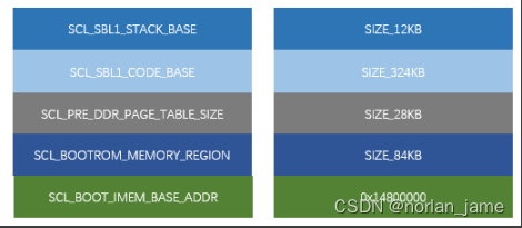
需要注意的是因为到目前为止,外部的DRAM还没有初始化,所以这里设置的栈的地址是在SOC内部的IMEM中,部分内存分布如下:
sbl1_main_ctl
sbl1_main_ctl函数代码如下:
void sbl1_main_ctl(boot_pbl_shared_data_type *pbl_shared)
{
DALResult bsy_wait_init;
/* Configure Domain access control register */
mmu_set_dacr(DACR_ALL_DOMAIN_CLIENTS);
/* Retrieve info passed from PBL*/
sbl1_retrieve_shared_info_from_pbl(pbl_shared);
/* Initialize shared functions structure - provides other images with function pointers in Loader */
boot_shared_functions_register();
/* Initialize SBL memory map */
sbl1_populate_initial_mem_map(&bl_shared_data);
/* Calculate the SBL start time for use during boot logger initialization. */
sbl_start_time = CALCULATE_TIMESTAMP(HWIO_IN(TIMETICK_CLK));
/* Initialize busywait module Note: required before logger init due to uart driver dependency on busywait */
BL_VERIFY((bsy_wait_init=boot_busywait_init()) == DAL_SUCCESS, (uint16)bsy_wait_init|BL_ERROR_GROUP_BUSYWAIT);
/* Enable qdss workaround */
BL_VERIFY(boot_clock_debug_init() == TRUE, FALSE|BL_ERROR_GROUP_CLK );
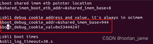
/* Enter debug mode if debug cookie is set */
sbl1_debug_mode_enter();
/* Initialize the stack protection canary */
boot_init_stack_chk_canary();
/* Initialize boot shared imem */
boot_shared_imem_init(&bl_shared_data);
/* Initialize the ChipInfo driver */
ChipInfo_Init();
/* Initialize the QSEE interface */
sbl1_init_sbl_qsee_interface(&bl_shared_data, &sbl_verified_info);
/* Initialize dal heap using internal memory */
boot_DALSYS_HeapInit(boot_internal_heap, BOOT_INTERNAL_HEAP_SIZE, FALSE);
/* Initialize DAL, needs to be called before modules that uses DAL */
boot_DALSYS_InitMod(NULL);
/* Initialize boot logger and start the log timer.
This must be done after sbl1_retrieve_shared_info_from_pbl
and boot_secboot_ftbl_init. */
sbl1_boot_logger_init(&boot_log_data, pbl_shared);
boot_log_set_meta_info(boot_log_data.meta_info_start);
/* Set hash algorithm */
BL_VERIFY(boot_set_hash_algo(SBL_HASH_SHA256) == BL_ERR_NONE, BL_ERR_UNSUPPORTED_HASH_ALGO|BL_ERROR_GROUP_BOOT);
/* Call sbl1_hw_init to config pmic device so we can use PS_HOLD to reset */
sbl1_hw_init();
#ifdef FEATURE_DEVICEPROGRAMMER_IMAGE
/* Enter device programmer does not return */
device_programmer_init(&bl_shared_data, pbl_shared);
#else
/* Store the sbl1 hash to shared imem */
boot_store_tpm_hash_block(&bl_shared_data, &sbl_verified_info);
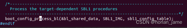
/*-----------------------------------------------------------------------
Process the target-dependent SBL1 procedures
-----------------------------------------------------------------------*/
boot_config_process_bl(&bl_shared_data, SBL1_IMG, sbl1_config_table);
#endif
} /* sbl1_main_ctl() */mmu_set_dacr
.type mmu_set_dacr, @function
mmu_set_dacr:
// Configure Domain access control register register DACR to have appropriate
// permissions for different domains.
// Check the current Exception Level
//----------------------------------
MRS x1, CurrentEL
LSR x1, x1, #2
CMP x1, #3
BGE set_dacr32_el2
MOV x1, #0x00300000 // Sets bits 21, 20 so that SIMD access do not cause exception
MSR CPACR_EL1, x1
B set_dacr32_end
set_dacr32_el2:
MSR DACR32_EL2, x0 // Write DACR
DSB SY
ISB SY
set_dacr32_end:
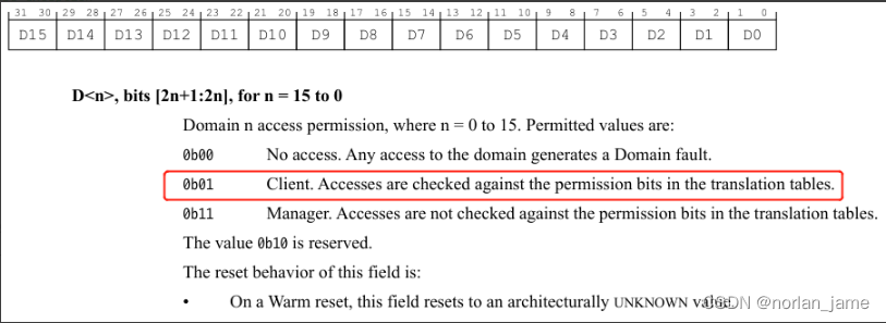
ret通过上面代码配置DACR寄存器值为:0x55555555,即每个域配置值为0x01
sbl1_retrieve_shared_info_from_pbl
这个函数主要负责对PBL共享过来的数据进行处理,将一部分数据赋值给sbl1_pbl_shared_data,并对bl_shared_data结构体进行了初始化.
boot_shared_functions_register
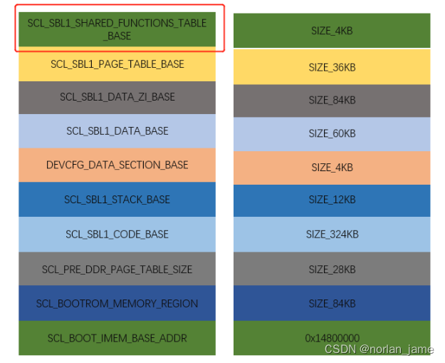
这个函数将会把一些函数注册到IMEM如下内存地址中
sbl1_populate_initial_mem_map
初始化MMU,并且enable MMU/dcache功能,如果是QFILE模式的镜像,还会调用device_programmer_memmap_init做更多的初始化动作.
boot_busywait_init
初始化timer时钟,让sbl支持delay功能,这里使用busywait(pause_time_us);来达到delay目的
Clock_DebugInit
初始化8155时钟
boolean Clock_DebugInit(void)
{
int i;
uint32 mask;
boolean chip_SM8150_AU_V1 = FALSE;
HWIO_OUTF(GCC_GPLL0_USER_CTL, PLLOUT_EVEN, 1);
/* V1 SM8150 Automotive parts are undervolted, and cannot use CPU Nominal
* until that is fixed later in boot */
if( Clock_ChipVersion() == V1 )
{
uint32 raw_id = HWIO_INF(TLMM_HW_REVISION_NUMBER, PRODUCT_DEVICE_ID);
if ( (raw_id == CHIPINFO_PARTNUM_SDM855A) || (raw_id == CHIPINFO_PARTNUM_SA8150) ||
(raw_id == CHIPINFO_PARTNUM_SA8150P) )
{
chip_SM8150_AU_V1 = TRUE;
}
}
if(chip_SM8150_AU_V1 == FALSE)
{
/* To improve boot time, speed up the CPU and buses */
if( ! Clock_SetSysPerfLevel(CLOCK_BOOT_PERF_DEFAULT)) return FALSE;
if( ! Clock_SetCPUPerfLevel(CLOCK_BOOT_PERF_DEFAULT)) return FALSE;
}
/* Enable required boot power domains */
for( i=0; ClockRequiredPowerDomains[i] != 0; i++)
{
Clock_PowerDomainEnable (ClockRequiredPowerDomains[i]);
}
/* Enable the RPMh and Boot required clocks */
Clock_ToggleEnableList( ClockRequiredList );
// For power savings, it enables only when gcc_debug_clk is enabled. Skip status check.
HWIO_OUTF(GCC_SPDM_DEBUG_CY_CBCR, CLK_ENABLE, 1);
/* On SDM8150V2, the REFGEN was fixed */
if( Clock_ChipVersion() == V1 )
{
HWIO_OUT(PERIPH_SS_PHY_REFGEN_NORTH_RSM_CNTRL, 0x08);
HWIO_OUT(PERIPH_SS_PHY_REFGEN_NORTH_RESTRIM_BYPASS_CODE, 0x4E);
HWIO_OUT(PHY_REFGEN_SOUTH_RSM_CNTRL, 0x08);
HWIO_OUT(PHY_REFGEN_SOUTH_RESTRIM_BYPASS_CODE, 0x4E);
}
Clock_AGGRENOCInit();
/*
* This clock required for MMNOC power collapse to work. If not enabled, the
* MMNOC GDS HW controller will get stuck waiting on an ACK from MMNOC.
* Don't include as part of ClockRequiredList, since Clock_ToggleClock will
* poll for CLK_OFF = 0, but this clock will be forced off by the MMNOC GDSC
* at this point.
*/
HWIO_OUTF(GCC_MMNOC_AT_CBCR, CLK_ENABLE, 1);
/* Enable access to clock controllers */
Clock_ToggleClock(HWIO_GCC_GPU_CFG_AHB_CBCR_ADDR, CLK_TOGGLE_ENABLE);
/* Needed for Random Stack Canary */
HWIO_OUTF(GCC_APCS_CLOCK_BRANCH_ENA_VOTE, PRNG_AHB_CLK_ENA, 1);
/* Hold it on with an RPM vote, CR 2115680 */
HWIO_OUTF(GCC_RPM_CLOCK_BRANCH_ENA_VOTE, PRNG_AHB_CLK_ENA, 1);
mask =
HWIO_FMSK( GCC_RPM_CLOCK_BRANCH_ENA_VOTE_1, QUPV3_WRAP_0_S_AHB_CLK_ENA) |
HWIO_FMSK( GCC_RPM_CLOCK_BRANCH_ENA_VOTE_1, QUPV3_WRAP_0_M_AHB_CLK_ENA) |
HWIO_FMSK( GCC_RPM_CLOCK_BRANCH_ENA_VOTE_1, QUPV3_WRAP0_CORE_CLK_ENA) |
HWIO_FMSK( GCC_RPM_CLOCK_BRANCH_ENA_VOTE_1, QUPV3_WRAP0_CORE_2X_CLK_ENA) |
HWIO_FMSK( GCC_RPM_CLOCK_BRANCH_ENA_VOTE_1, QUPV3_WRAP_1_S_AHB_CLK_ENA) |
HWIO_FMSK( GCC_RPM_CLOCK_BRANCH_ENA_VOTE_1, QUPV3_WRAP_1_M_AHB_CLK_ENA) |
HWIO_FMSK( GCC_RPM_CLOCK_BRANCH_ENA_VOTE_1, QUPV3_WRAP1_CORE_CLK_ENA) |
HWIO_FMSK( GCC_RPM_CLOCK_BRANCH_ENA_VOTE_1, QUPV3_WRAP1_CORE_2X_CLK_ENA);
HWIO_OUTM( GCC_RPM_CLOCK_BRANCH_ENA_VOTE_1, mask, mask );
mask =
HWIO_FMSK( GCC_RPM_CLOCK_BRANCH_ENA_VOTE_2, QUPV3_WRAP_2_S_AHB_CLK_ENA) |
HWIO_FMSK( GCC_RPM_CLOCK_BRANCH_ENA_VOTE_2, QUPV3_WRAP_2_M_AHB_CLK_ENA) |
HWIO_FMSK( GCC_RPM_CLOCK_BRANCH_ENA_VOTE_2, QUPV3_WRAP2_CORE_CLK_ENA) |
HWIO_FMSK( GCC_RPM_CLOCK_BRANCH_ENA_VOTE_2, QUPV3_WRAP2_CORE_2X_CLK_ENA);
HWIO_OUTM( GCC_RPM_CLOCK_BRANCH_ENA_VOTE_2, mask, mask );
if( ! Clock_InitPLLStatic()) return FALSE;
if( ! Clock_InitCrypto(CLOCK_BOOT_PERF_DEFAULT) ) return FALSE;
return TRUE;
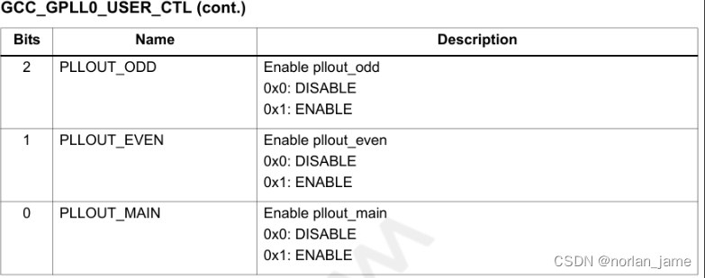
}HWIO_OUTF(GCC_GPLL0_USER_CTL, PLLOUT_EVEN, 1) 这行代码enable了PLL锁相环时钟的偶数分频(even division),这里有几个点:
1,HWIO_OUTF是一个宏函数,用于按照field配置寄存器,比如这里配置的是GCC_GPLL0_USER_CTL寄存器的PLLOUT_EVEN域为1
2,GCC_GPLL0_USER_CTL这个寄存器定义在QcomPkg/SDMPkg/855/Include/HALbootHWIO.h +7165
3,寄存器手册解释:
在接下来的代码中会初始化其他clock.
sbl1_debug_mode_enter
这个函数代码很简单:
static void sbl1_debug_mode_enter()
{
  volatile uint32 *boot_debug_cookie_ptr = (uint32 *)SBL1_DEBUG_COOKIE_ADDR;

  /* Loop here to wait for jtag attach if cookie value matches*/
  while(*boot_debug_cookie_ptr == SBL1_DEBUG_COOKIE_VAL);
}直接判断IMEM中的SBL1_DEBUG_COOKIE_ADDR地址,如果该地址指向的值等于SBL1_DEBUG_COOKIE_VAL(0x53444247),那么代码陷入死循环
这个值在哪里被写入呢?这个值在我们使用jtag工具调试SOC的时候,由T32调用debug脚本写入:SDMPkg/Tools/boot_debug_target_data.cmm. (什么是T32?)
boot_init_stack_chk_canary
初始化栈保护相关的值?
boot_shared_imem_init
初始化share imem这个部分内存,过程比较简单:
void boot_shared_imem_init(bl_shared_data_type *bl_shared_data)
{
  /*Make sure size of the cookie struct doesn't exceed the boot shared imem size*/
  BL_VERIFY(sizeof(struct boot_shared_imem_cookie_type) <=
            SHARED_IMEM_BOOT_SIZE,
            BL_ERR_COOKIE_TOO_BIG|BL_ERROR_GROUP_BOOT);

  /*First check to see if magic number is present*/
  if (boot_shared_imem_cookie_ptr != NULL)
  {
    if (boot_shared_imem_cookie_ptr->shared_imem_magic !=
        BOOT_SHARED_IMEM_MAGIC_NUM)
    {
      /*If magic number is not there then
        intialize the whole boot shared imem to 0xFFFFFFFF*/
      qmemset((void*)boot_shared_imem_cookie_ptr,
              SHARED_IMEM_REGION_DEF_VAL,
              SHARED_IMEM_BOOT_SIZE);

      boot_shared_imem_cookie_ptr->shared_imem_magic =
        BOOT_SHARED_IMEM_MAGIC_NUM;

      boot_shared_imem_cookie_ptr->shared_imem_version =
        BOOT_SHARED_IMEM_VERSION_NUM;

      boot_shared_imem_cookie_ptr->boot_device_type =
        boot_pbl_get_flash_type();

      dcache_flush_region((void *)SHARED_IMEM_BOOT_BASE, SHARED_IMEM_BOOT_SIZE);
    }
  }
}
先判断shared_imem_magic 这个值是否为BOOT_SHARED_IMEM_MAGIC_NUM,如果相等则意味着share imem已经被初始化过,否则重新对其初始化,并且保存boot_device_type等信息到这块内存中.
ChipInfo_Init
获取芯片信息
sbl1_init_sbl_qsee_interface
初始化QSEE(Secure execution environment)接口,比较重要的代码如下:
  /* Api to put DDR in self refresh */
  bl_shared_data->sbl_qsee_interface.ddr_enter_self_refresh = (uint64)boot_ddr_enter_self_refresh;

  /* Api to bring DDR out of self refresh */
  bl_shared_data->sbl_qsee_interface.ddr_exit_self_refresh = (uint64)boot_ddr_exit_self_refresh;

  /* Update QSEE interface with SBL auth information provided by PBL */
  qmemcpy(&(bl_shared_data->sbl_qsee_interface.boot_image_entry[0].image_verified_info),
          sbl1_auth_verified_info,
          sizeof(secboot_verified_info_type));
  /*
    sbl_qsee_interface.appsbl_entry_index is populated at the very end after
    loading appsbl image.
  */

  /* Update SBL entry with information not passed by PBL */
  bl_shared_data->sbl_qsee_interface.boot_image_entry[0].image_id = SECBOOT_SBL_SW_TYPE;
  bl_shared_data->sbl_qsee_interface.boot_image_entry[0].entry_point = SCL_SBL1_VECTOR_BASE;
  bl_shared_data->sbl_qsee_interface.number_images++;
}
boot_DALSYS_HeapInit
在internal memory中为DAL模块初始化堆
boot_DALSYS_InitMod
init DAL SYS, 什么是DAL?TODO
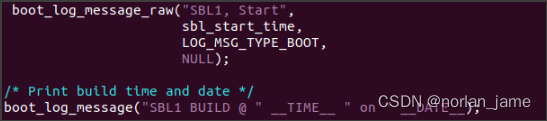
sbl1_boot_logger_init
这个函数主要负责初始化log模块,并且输出log以及时间戳。
static void sbl1_boot_logger_init
(
  boot_log_init_data *boot_log_data,
  boot_pbl_shared_data_type *pbl_shared
)
{
  /*initialize boot logger*/
  boot_log_init(boot_log_data);

  /*initialize boot logger*/
  boot_log_set_init_info_marker();

  /* Write PBL timestamp milestones into beginning of log */
  boot_pbl_log_milestones(pbl_shared);

  /*Set the reference time to 0 as the start of boot*/
  boot_log_set_ref_time(0);

  /* Add SBL start entry using stored time from beginning of sbl1_main_ctl */
  boot_log_message_raw("SBL1, Start",
                       sbl_start_time,
                       LOG_MSG_TYPE_BOOT,
                       NULL);

 /* Print build time and date */
 boot_log_message("SBL1 BUILD @ " __TIME__ " on " __DATE__);

}/* sbl1_boot_logger_init */
主要内容:
- 初始化log所需要的内存
- 初始化uart&timer
- 从PBL共享数据中提取出来PBL的log
- 输出SBL start的log
boot_log_set_meta_info
作用未知? todo
boot_set_hash_algo
设置hash算法?todo
sbl1_hw_init
void sbl1_hw_init()
{
TsensResultType status;
#ifndef BOOT_PRE_SILICON
#ifdef FEATURE_BOOT_FAST_DEBUG
/* Check if we are going to enter debug mode */
boot_debug_mode_enter();
#endif
#endif
/* Initialize temperature sensor */
status = boot_Tsens_Init();
BL_VERIFY(status == TSENS_SUCCESS,(uint16)status|BL_ERROR_GROUP_TSENS);
/* Check the temperature */
boot_check_device_temp();
/* Put High Speed QUSB2 PHY in non-drive mode. */
boot_qusb_ldr_utils_hs_phy_nondrive_mode_set();
#if (!defined(FEATURE_RUMI_BOOT))
/* Calling here to ensure eeprom init goes fine for CDT read */
boot_pre_i2c_clock_init();
#endif /*FEATURE_RUMI_BOOT*/
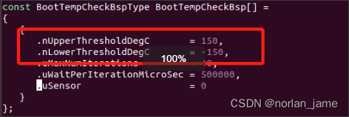
} /* sbl1_hw_init() *这个函数主要负责:
- 初始化temperature sensor
- 读取当前温度状态,判断是否温度是否在可启动范围内
- 初始化usb phy为none模式
从代码里面,我们可以看到8155的最低和最高启动温度分别是多少:
device_programmer_init
需要注意的是这个函数只有编译为QFIL专用的镜像的情况下才会被编译:
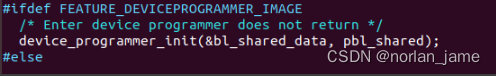
这里面的细节可以参看 prog_firehose_ddr.elf如果工作?(todo)
代码运行到这里会发散为两个分支,其中一个就是这里的device_programmer_init,另外一个是正常启动后续XBL镜像
boot_store_tpm_hash_block
保存hash值到imem中,以备后续校验时使用(secure boot?)
boot_config_process_bl
在sbl1_main_ctl函数的最后会调用boot_config_process_bl来加载运行后续的镜像:
其中最重要的是sbl1_config_table 这个配置表:

我们需要分析boot_config_process_bl这个函数本身以及sbl1_config_table 中的函数接口.
boot_config_process_bl的代码如下:
void boot_config_process_bl
(
  bl_shared_data_type *bl_shared_data,
  image_type host_img,
  boot_configuration_table_entry * boot_config_table
)
{
  boot_configuration_table_entry *curr_entry = NULL;

  BL_VERIFY( bl_shared_data != NULL && boot_config_table != NULL,
             BL_ERR_NULL_PTR_PASSED|BL_ERROR_GROUP_BOOT);

  /* For every entry in the boot configuration table */
  for(curr_entry = boot_config_table;
      curr_entry->host_img_id != NONE_IMG;
      curr_entry++)
  {
    /* Process entries sequentially only for the specific host_img */
    if(curr_entry->host_img_id == host_img)
    {
      boot_config_process_entry(bl_shared_data,
                                curr_entry);
    }
  }

  return;
}这个函数会根据sbl1_config_table 这个配置表依次加载运行镜像,最后跳转到XBL的下一阶段. 后面我们会分析这个配置表里面主要的内容.
boot_config_process_entry
boot_config_process_bl函数最主要的实现是在boot_config_process_entry中,这个函数的主要流程如下
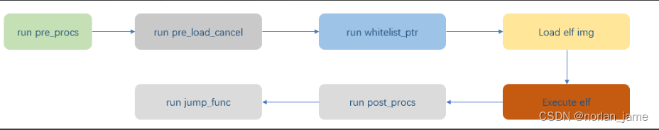
但是需要注意的是不是每一个节点都会完整的执行上面的流程,比如APDP这个节点,就没有执行load elf img这个操作.
分析XBL的启动log发现,真正会被load的img有下面几个:
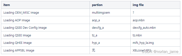 在config表中,真正跳转的只有一个函数:qsee_jump_func,虽然sti_jump_func也配置了,但是STI image并没有刷写也不会被加载,所以也不会跳转.
apdp_pre_procs
这个是个函数指针数组,也就意味着数组中的每个函数都会运行一次.
boot_procedure_func_type apdp_pre_procs[] =
{
  /* Save reset register logs */
  boot_save_reset_register_log,

  /* Initialize the flash device */
  boot_flash_init,


  sbl1_update_partition_ids,

  /* Initialize XBL config Lib */
  sbl1_xblconfig_init,

  /* Initialize the default CDT before reading CDT from flash */
  boot_config_data_table_default_init,

  /* Copy the configure data table from flash */
  boot_config_data_table_init,

  /* Store platform id */
  sbl1_hw_platform_pre_ddr,

  /* Initialize PMIC and railway driver */
  sbl1_hw_pre_ddr_init,

  /* Check if forced dload timeout reset cookie is set */
  boot_dload_handle_forced_dload_timeout,

  /* Configure ddr parameters based on eeprom CDT table data. */
  sbl1_ddr_set_params,

  /* Initialize DDR */
  (boot_procedure_func_type)sbl1_ddr_init,

  /* Train DDR if applicable */
  sbl1_do_ddr_training,

  /*----------------------------------------------------------------------
   Run deviceprogrammer if compiling the deviceprogrammer_ddr image.
   In XBL builds the function below is stubbed out (does nothing)
  ----------------------------------------------------------------------*/
  sbl1_hand_control_to_devprog_ddr,

#ifndef FEATURE_DEVICEPROGRAMMER_IMAGE

  /* Run DDI testing if tests exist */
  boot_ddi_entry,

  /* Initialize SBL1 DDR ZI region, relocate boot log to DDR */
  sbl1_post_ddr_init,

  sbl1_hw_init_secondary,

#endif /*FEATURE_DEVICEPROGRAMMER_IMAGE*/

  /* Last entry in the table. */
  NULL
}boot_save_reset_register_log:从PBL的栈中备份reset register信息,其实是备份下面这些寄存器,这些寄存器在debug一些异常问题时非常重要.
ERR_RESET_SYS_SP = 0,
ERR_RESET_SYS_LR,
ERR_RESET_IRQ_SP,
ERR_RESET_IRQ_LR,
ERR_RESET_FIQ_SP,
ERR_RESET_FIQ_LR,
ERR_RESET_ABT_SP,
ERR_RESET_ABT_LR,
ERR_RESET_UDF_SP,
ERR_RESET_UDF_LR,
ERR_RESET_SVC_R0,
ERR_RESET_SVC_R1,
ERR_RESET_SVC_R2,
ERR_RESET_SVC_R3,
ERR_RESET_SVC_R4,
ERR_RESET_SVC_R5,
ERR_RESET_SVC_R6,
ERR_RESET_SVC_R7,
ERR_RESET_SVC_R8,
ERR_RESET_SVC_R9,
ERR_RESET_SVC_R10,
ERR_RESET_SVC_R11,
ERR_RESET_SVC_R12,
ERR_RESET_SVC_SP,
ERR_RESET_SVC_LR,
ERR_RESET_SVC_PC,boot_flash_init:根据PBL传递的boot media类型初始化对应的驱动
sbl1_update_partition_ids:从misc分区读取启动模式,比如A/B分区,recovery模式。这里通过boot_flash_configure_target_image函数通过唯一的GUID去读取misc分区数据,根据读取到的数据判定是从那个分区启动
![]()
这里的GUID(XBLLoader/boot_gpt_partition_id.c)与partition_la.xml中的GUID是一致的

 sbl1_xblconfig_init:作用未知
boot_config_data_table_default_init & boot_config_data_table_init:初始化默认CDT(config data table)表
sbl1_hw_platform_pre_ddr:根据cdt中的platform id配置ddr参数
sbl1_hw_pre_ddr_init:初始化pmic,设置电压?
boot_dload_handle_forced_dload_timeout:检测dload timeout,作用未知
sbl1_ddr_set_params:配置ddr参数
sbl1_ddr_init:初始化ddr硬件
sbl1_do_ddr_training:traning ddr
sbl1_hand_control_to_devprog_ddr:QFIL模式专用,作用未知
sbl1_post_ddr_init: 把page table copy到ddr中,最后调用sbl1_move_boot_log_to_ddr,把启动log保存到DDR中.
sbl1_hw_init_secondary: 初始化时钟
apdp_load_cancel
确认APDP分区是否存在,以及是否完整,如果是合法完整的img,则会加载,否则不会加载
apdp_post_procs
1,调用接口保存一部分的share 信息到DDR中(预留给AOP使用)
2,初始化tlmm模块(gpio)
qsee_jump_func
这个函数主要做了几个事情:
- 调用dcache_flush_region刷新dcache
- turn off vibration
- 打印"SBL1, End" log
- 获取qsee入口(tz.mbn)
- 保存xbl_core入口
- 调用boot_fastcall_tz_no_rsp跳转到trustzone中
配置表中的SCL_XBL_CORE_CODE_BASE 即为APPSBL的入口地址,这个地址被定义为:0x9FC00000,这是个内存地址,也就意味着后续的代码将在DDR中运行.
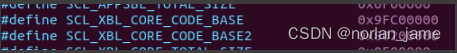
0x9FC00000 这个地址就是前面我们提到的SDMPkg/855/AU/buildconfig_AU.json文件中的XBL_Core组件定义的地址.
After SBL1
前面说到在SBL1的最后阶段会跳转到trustzone中,trustzone内部细节目前还不是很清楚,但是目前确定的是:
- tz会根据devcfg_auto.mbn的配置信息配置gpio/QUP3模块
- trustzone去跳转到mifs_hyp_la.img中
在mifs_hyp_la.img中会根据一些特定条件判断是执行正常启动顺序,还是跳转xbl core中(fastboot模式),比如启动时在串口上长按Q键
总结
通过本文我们搞清楚了以下内容:
- xbl如何编译及编译过程,如何生成的输出文件
- 8155 启动过程中都需要加载那些镜像,以及这些镜像的作用分别是什么
- 8155的启动细节,什么阶段跑的是什么代码
比较重要的点:
1,xbl.elf及xbl_config.elf的作用及组成
xbl.elf由两个部分组成:XBL_loader 及 XBL_core.
XBL_loader:准确来说应该被叫做SBL1,会被PBL加载到IMEM中运行,本文大部分在研究sbl1的内容.
XBL_core: 本质为UEFI,在正常启动流程中,只是会被加载而不被运行,只有特定条件触发(hotkey)时才会跳转
xbl_config.elf: pmic配置信息
2,8155如何记录boot log信息的?
8155记录了从PBL到HLOS之间所有的boot log,系统启动完成之后也可以获取到完整的boot log,8155是如何记录以及保存这些信息就很有意思
- 在PBL阶段,boot信息保存在IMEM中
- SBL被加载到IMEM后,这些boot信息会作为参数传递给SBL
- SBL完成对DDR的初始化后,这些信息会被重定向到DDR中(其中也包含了其他的page table)
- SBL跳转后,后续模块直接访问DDR特定地址即可获取/修改BOOT log
3,QFIL软件是如何运作的?
本文没有太多对QFIL软件是如何运作的,但是梳理整个boot流程的代码,我们现在能了解到QFIL是如何运作的
8155在强制进入QFIL模式时,本质上是从usb启动的,大致的流程:
1,通过按键或者cookie通知8155的PBL进入QFIL模式
2,PC load prog_firehose_ddr.elf 或者 prog_firehose_lite.elf到 IMEM中
3,prog_firehose程序通过Sahara 协议与PC通信,执行可能的操作,支持的操作非常多,包括读取分区表信息,对某个分区进行读写擦除
4,ddr.efl与lite.elf 两个镜像区别在于,ddr会在操作的时候初始化并使用dram,而lite则完全不会使用到ddr,在ddr有问题的情况下,一定要用lite进行操作
5,Sahara 协议类似于ftp协议,但是存在不同
6,QFIL软件打印的所有log都是prog_firehose输出的
7,prog_firehose负责对PC上的xml文件进行解析
4,8155的reset status & boot_fail_count 及启动温度
8155存在reset status寄存器,在不断电的情况下记录上一次异常reset的原因
同时PBL中存在boot_fail_count,用于记录启动失败次数,这个数值boot整个流程中都可以保留
8155在启动过程中会通过温度传感器读取当前cpu温度,目前8155设定的启动温度范围是 -150°~150°
5,8155的启动流程大致是怎样的?
本文大部分内容都是在接收sbl1阶段的代码细节,但是通过对sbl1最后的跳转阶段的代码分析,还是有不少的内容与我们之前的理解可能不太一样。
1,sbl1代码会被加载到IMEM中运行
2,XBL core代码只是会被加载,并不一定会运行
3,sbl1最后跳转到了trust zone中,并且通过trust zone设置了QSEE环境(高通可信执行环境)
4,在QSEE中加载启动了mifs_hyp_la.img,这个部分已经算是QNX的内容了(HLOS)
5,是否进入fastboot的判断是在mifs_hyp_la中判断的,当判断到要进入fastboot时,8155会跳转到XBL core中运行
6,XBL core 默认会通过Linuxloader这个app跳转到fastboot中
7,XBL core支持非常多的功能,不仅仅有Shell,也包含了EBL模式:
Shell:
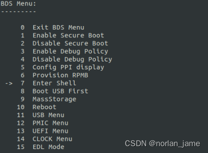
EBL:
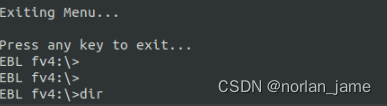
8,EBL 模式支持切换分区,执行各种各样的测试程序
9,XBL支持多线程运行任务
6,MISC分区的作用?
A/B/recovery分区的切换,以及是否进入EDL模式都可以通过写入flag到MISC分区来实现
7,进入UEFI shell的方法
通过下面patch进入UEFI shell,同时需要烧录tools.fv 到toolsfv分区
diff --git a/boot_images/QcomPkg/Library/PlatformBdsLib/PlatformBdsLib.c b/boot_images/QcomPkg/Library/PlatformBdsLib/PlatformBdsLib.c
index 9fde47f4..a83dc900 100755
--- a/boot_images/QcomPkg/Library/PlatformBdsLib/PlatformBdsLib.c
+++ b/boot_images/QcomPkg/Library/PlatformBdsLib/PlatformBdsLib.c
@@ -566,7 +566,8 @@ PlatformBdsDetectHotKey (VOID)
     }
   }

-  if (GotoMenu)
+  // for debug enter menu force
+//  if (GotoMenu)
   {
     EnableSynchronousSerialPortIO ();

@@ -1384,7 +1385,8 @@ PlatformBdsInitEx (BDS_INIT_OPTION *InitOption)
    *   So do NOT modify any code in this WARNING context.
    *
    */
-  if (!RETAIL)
+  //for debug
+//  if (!RETAIL)
   {
     /* Detect hotkey for development purposes
      * If enabled in PROD image this would be a SECURITY HOLE
8,进入Embedded Boot Loader (EBL)的方法
通过下面patch进入EBL,同时需要烧录tools.fv 到toolsfv分区, 在启动过程中按Q键
diff --git a/boot_images/QcomPkg/SDMPkg/855/AU/uefiplat.cfg b/boot_images/QcomPkg/SDMPkg/855/AU/uefiplat.cfg
index dc047555..c6f7ee38 100755
--- a/boot_images/QcomPkg/SDMPkg/855/AU/uefiplat.cfg
+++ b/boot_images/QcomPkg/SDMPkg/855/AU/uefiplat.cfg
@@ -118,8 +118,9 @@ TzAppsRegnAddr = 0x87900000
 TzAppsRegnSize = 0x02200000

 ## Default app to boot in platform BDS init
+DefaultChargerApp = "SPITest"
 #DefaultChargerApp = "QcomChargerApp"
-DefaultBDSBootApp = "LinuxLoader"
+#DefaultBDSBootApp = "LinuxLoader"

 ## LogFs partition ##
 ## NOTE: Ensure logs 8MB bin is flashed from /Tools/binaries ##
9,待分析问题1:tz是如何加载运行hyp_a分区的镜像的?
todo
10,XBL在什么时候重新对UFS初始化的?
PBL在上电之后在romcode中使用基本参数对UFS进行了第一次初始化,然后在apdp_pre_procs初始化序列中,调用boot_flash_init 函数重新对UFS进行初始化以保证后续bootimage的加载速度.
Acronyms
| Acronym or term | Definition |
|---|---|
| AOP | Always on processor |
| AOSS | Always on Sub-system |
| APDP | Application processor debug policy |
| XBL config | PMIC settings and DDR configurations are packed into the XBLConfig binary item |


 508
508

 被折叠的 条评论
为什么被折叠?
被折叠的 条评论
为什么被折叠?
 到【灌水乐园】发言


