


前言
STM32------PWM
提示:以下是本篇文章正文内容,下面案例可供参考
一、PWM概述
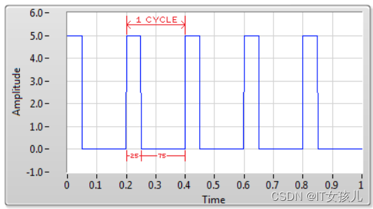
PWM(Pulse Width Modulation),脉冲宽度调制。
脉冲:方波,频率(freq)
宽度:高电平的宽度,占空比(duty)
占空比25%
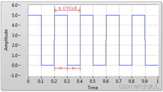
占空比50%
占空比75%

二、库函数
1.GPIO引脚映射
代码如下(示例):
/**
  * @brief  Changes the mapping of the specified pin.
  * @param  GPIOx: where x can be (A..K) to select the GPIO peripheral for STM32F405xx/407xx and STM32F415xx/417xx devices
  *                      x can be (A..I) to select the GPIO peripheral for STM32F42xxx/43xxx devices.
  *                      x can be (A, B, C, D and H) to select the GPIO peripheral for STM32F401xx devices.
  * @param  GPIO_PinSource: specifies the pin for the Alternate function.
  *         This parameter can be GPIO_PinSourcex where x can be (0..15).
  * @param  GPIO_AFSelection: selects the pin to used as Alternate function.
  *          This parameter can be one of the following values:
.......................................................
  *            @arg GPIO_AF_TIM14: Connect TIM14 pins to AF9
.......................................................
  * @retval None
  */
void GPIO_PinAFConfig(GPIO_TypeDef* GPIOx, uint16_t GPIO_PinSource, uint8_t GPIO_AF)
2.定时器通道1配置
代码如下(示例):
/**
  * @brief  Initializes the TIMx Channel1 according to the specified parameters in
  *         the TIM_OCInitStruct.
  * @param  TIMx: where x can be 1 to 14 except 6 and 7, to select the TIM peripheral.
  * @param  TIM_OCInitStruct: pointer to a TIM_OCInitTypeDef structure that contains
  *         the configuration information for the specified TIM peripheral.
  * @retval None
  */
void TIM_OC1Init(TIM_TypeDef* TIMx, TIM_OCInitTypeDef* TIM_OCInitStruct)
注:
通道1:TIM_OC1Init
通道2:TIM_OC2Init
通道3:TIM_OC3Init
通道4:TIM_OC4Init
3.定时器通道1比较值
/**
  * @brief  Sets the TIMx Capture Compare1 Register value
  * @param  TIMx: where x can be 1 to 14 except 6 and 7, to select the TIM peripheral.
  * @param  Compare1: specifies the Capture Compare1 register new value.
  * @retval None
  */
void TIM_SetCompare1(TIM_TypeDef* TIMx, uint32_t Compare1)
注:
通道1:TIM_SetCompare1
通道2:TIM_SetCompare2
通道3:TIM_SetCompare3
通道4:TIM_SetCompare4
三、PWM1和PWM2模式
1.定义
PWM 模式 1——只要 TIMx_CNT < TIMx_CCR1,通道 1 便为有效状态,否则为无效状态。
PWM 模式 2——只要 TIMx_CNT < TIMx_CCR1,通道 1 便为无效状态,否则为有效状态。
TIMx_CNT由TIM_TimeBaseStructure.TIM_Period决定;
TIMx_CCR1由TIM_SetComparex(x:1、2、3、4)函数决定;
有效状态由TIM_OCInitStructure.TIM_OCPolarity决定;
频率值:由计数值决定
占空比:由比较值决定
2.示例
TIM_TimeBaseStructure.TIM_Period = (10000/100)-1;		//输出脉冲的频率100Hz
......
TIM_OCInitStructure.TIM_OCMode = TIM_OCMode_PWM1;		//通道工作在PWM模式1
......
TIM_OCInitStructure.TIM_OCPolarity = TIM_OCPolarity_High;	//有效状态为高电平
......
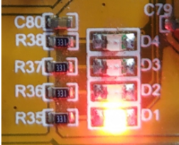
占空比20%
TIM_SetCompare1(TIM14,20);
LED1灯光亮度如下:
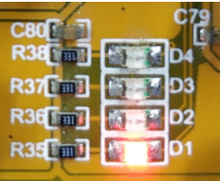
占空比50%
TIM_SetCompare1(TIM14,50);
LED1灯光亮度如下:
四、dc调光与pwm调光区别
1.DC调光是一种调节亮度的方式
为了让用户在不同光线条件下正常观看手机上的内容,屏幕需要相应地改变亮度。其中一种调节亮度的方式就叫“DC调光”。
DC调光的原理非常简单,就是通过提高或降低电路功率来改变屏幕的亮度。功率 = 电压 x 电流,所以改变电压或电流都能改变屏幕亮度。
2.PWM调光是另一种调节亮度的方式
在PWM调光屏幕上,调节亮度并不靠改变功率,而是靠屏幕的亮、灭交替。PWM调光屏幕点亮时并不是持续发光的,而是在不停地点亮、熄灭屏幕。当亮、灭交替够快时,肉眼就会认为手机一直在亮。
在屏幕亮、灭的过程中,灭屏状态持续时间越长,屏幕给肉眼的观感就是亮度越低。点亮的时间越长,灭屏时间就相应减少,屏幕就会变亮。
亮、灭交替的速度越低,对人眼造成不利影响的可能性就越大。但这并不是绝对的,因为每个人对于“闪烁”的敏感程度不同。比如看同一块PWM屏幕,有人没事,有人就会感到疲劳。如果你属于眼睛十分敏感的那部分人,你可能就需要使用高频PWM调光手机,甚至DC调光手机了。
五、呼吸灯源码下载
总结
以上就是今天要讲的内容,本文仅仅简单介绍了STM32------PWM的使用,而STM32的其他一些使用模块,请各位大神移步本博主其他文章或是关注博主等待后续发布。


 9894
9894


 被折叠的 条评论
为什么被折叠?
被折叠的 条评论
为什么被折叠?
 到【灌水乐园】发言


