


Online CRC Calculation
Online CRC Calculation - GHSInfrotronic
Online CRC Calculation
Online CRC Calculation
Be careful: there are several ways to realize a CRC. They differ (at least) in the way which bit is shifted in first and also in the initialization of the flipflops.
Enter your CRC polynomial as bit sequence ("100110001") here:
100110001
This gives the following CRC polynomial (press RETURN to update):
P(x) = x8+ x5+ x4+ x0
Enter your message as sequence of hex bytes here. Don't care about whitespaces since they will be ignored.
E100CAFE
Press RETURN or the Calculate button below to see the CRC checksum here:
$ 23 (hexadecimal) % 00100011 (binary, see calculation details here) ! 35 (decimal)
P(x) = x8+ x5+ x4+ x0
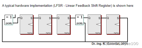
A typical hardware implementation (LFSR - Linear Feedback Shift Register) is shown here:

The input bits are shifted into the very left XOR gate. The MSB (leftmost bit) of each byte is shifted in first.
Each flipflop represents a single CRC output bit. The leftmost flipflop is the MSB of the CRC. This implementation doesn't need to augment the serial input message with zeros.
Note that in our case the flipflops are cleared to zeros at the beginning of each CRC calculation.
A simple VERILOG implementation of the above polynom is shown here. You can directly copy the source snippet to your code (distributed under LGPL):
// ==========================================================================
// CRC Generation Unit - Linear Feedback Shift Register implementation
// (c) Kay Gorontzi, GHSi.de, distributed under the terms of LGPL
// ==========================================================================
module CRC_Unit(BITVAL, BITSTRB, CLEAR, CRC);
   input         BITVAL;                            // Next input bit
   input         BITSTRB;                           // Current bit valid (Clock)
   input         CLEAR;                             // Init CRC value
   output [7:0] CRC;                               // Current output CRC value

   reg    [7:0] CRC;                               // We need output registers
   wire          inv;

   assign inv = BITVAL ^ CRC[7];                   // XOR required?

   always @(posedge BITSTRB or posedge CLEAR) begin
      if (CLEAR) begin
         CRC = 0;                                  // Init before calculation
         end
      else begin
         CRC[7] = CRC[6];
         CRC[6] = CRC[5];
         CRC[5] = CRC[4] ^ inv;
         CRC[4] = CRC[3] ^ inv;
         CRC[3] = CRC[2];
         CRC[2] = CRC[1];
         CRC[1] = CRC[0];
         CRC[0] = inv;
         end
      end

endmodule
A simple C implementation of the above polynom is shown in the following code. Again, you can directly copy the source snippet to your code (distributed under LGPL):
// ==========================================================================
// CRC Generation Unit - Linear Feedback Shift Register implementation
// (c) Kay Gorontzi, GHSi.de, distributed under the terms of LGPL
// ==========================================================================
char *MakeCRC(char *BitString)
   {
   static char Res[9];                                 // CRC Result
   char CRC[8];
   int  i;
   char DoInvert;

   for (i=0; i<8; ++i)  CRC[i] = 0;                    // Init before calculation

   for (i=0; i<strlen(BitString); ++i)
      {
      DoInvert = ('1'==BitString[i]) ^ CRC[7];         // XOR required?

      CRC[7] = CRC[6];
      CRC[6] = CRC[5];
      CRC[5] = CRC[4] ^ DoInvert;
      CRC[4] = CRC[3] ^ DoInvert;
      CRC[3] = CRC[2];
      CRC[2] = CRC[1];
      CRC[1] = CRC[0];
      CRC[0] = DoInvert;
      }

   for (i=0; i<8; ++i)  Res[7-i] = CRC[i] ? '1' : '0'; // Convert binary to ASCII
   Res[8] = 0;                                         // Set string terminator

   return(Res);
   }
// A simple test driver:

#include <stdio.h>

int main()
   {
   char *Data, *Result;                                       // Declare two strings

   Data = "1101000101000111";
   Result = MakeCRC(Data);                                    // Calculate CRC

   printf("CRC of [%s] is [%s] with P=[100110001]\n", Data, Result);

   return(0);
   }
P(x) = x5+ x2+ x0
Be careful: there are several ways to realize a CRC. They differ (at least) in the way which bit is shifted in first and also in the initialization of the flipflops.
Enter your CRC polynomial as bit sequence ("100110001") here:
This gives the following CRC polynomial (press RETURN to update):
P(x) = x5+ x2+ x0
Enter your message as sequence of hex bytes here. Don't care about whitespaces since they will be ignored.
Press RETURN or the Calculate button below to see the CRC checksum here:
00000 is the initial CRC value (hide details)
Next hex digit [E]:
Shift in of [1] results in 00101
Shift in of [1] results in 01111
Shift in of [1] results in 11011
Shift in of [0] results in 10011
Next hex digit [1]:
Shift in of [0] results in 00011
Shift in of [0] results in 00110
Shift in of [0] results in 01100
Shift in of [1] results in 11101
Next hex digit [0]:
Shift in of [0] results in 11111
Shift in of [0] results in 11011
Shift in of [0] results in 10011
Shift in of [0] results in 00011
Next hex digit [0]:
Shift in of [0] results in 00110
Shift in of [0] results in 01100
Shift in of [0] results in 11000
Shift in of [0] results in 10101
Next hex digit [C]:
Shift in of [1] results in 01010
Shift in of [1] results in 10001
Shift in of [0] results in 00111
Shift in of [0] results in 01110
Next hex digit [A]:
Shift in of [1] results in 11001
Shift in of [0] results in 10111
Shift in of [1] results in 01110
Shift in of [0] results in 11100
Next hex digit [F]:
Shift in of [1] results in 11000
Shift in of [1] results in 10000
Shift in of [1] results in 00000
Shift in of [1] results in 00101
Next hex digit [E]:
Shift in of [1] results in 01111
Shift in of [1] results in 11011
Shift in of [1] results in 10110
Shift in of [0] results in 01001
$ 09 (hexadecimal) % 01001 (binary) ! 9 (decimal)
A typical hardware implementation (LFSR - Linear Feedback Shift Register) is shown here:
The input bits are shifted into the very left XOR gate. The MSB (leftmost bit) of each byte is shifted in first.
Each flipflop represents a single CRC output bit. The leftmost flipflop is the MSB of the CRC. This implementation doesn't need to augment the serial input message with zeros.
Note that in our case the flipflops are cleared to zeros at the beginning of each CRC calculation.
A simple VERILOG implementation of the above polynom is shown here. You can directly copy the source snippet to your code (distributed under LGPL):
// ==========================================================================
// CRC Generation Unit - Linear Feedback Shift Register implementation
// (c) Kay Gorontzi, GHSi.de, distributed under the terms of LGPL
// ==========================================================================
module CRC_Unit(BITVAL, BITSTRB, CLEAR, CRC);
   input        BITVAL;                            // Next input bit
   input        BITSTRB;                           // Current bit valid (Clock)
   input        CLEAR;                             // Init CRC value
   output [4:0] CRC;                               // Current output CRC value

   reg    [4:0] CRC;                               // We need output registers
   wire         inv;

   assign inv = BITVAL ^ CRC[4];                   // XOR required?

   always @(posedge BITSTRB or posedge CLEAR) begin
      if (CLEAR) begin
         CRC = 0;                                  // Init before calculation
         end
      else begin
         CRC[4] = CRC[3];
         CRC[3] = CRC[2];
         CRC[2] = CRC[1] ^ inv;
         CRC[1] = CRC[0];
         CRC[0] = inv;
         end
      end

endmodule
A simple C implementation of the above polynom is shown in the following code. Again, you can directly copy the source snippet to your code (distributed under LGPL):
// ==========================================================================
// CRC Generation Unit - Linear Feedback Shift Register implementation
// (c) Kay Gorontzi, GHSi.de, distributed under the terms of LGPL
// ==========================================================================
char *MakeCRC(char *BitString)
   {
   static char Res[6];                                 // CRC Result
   char CRC[5];
   int  i;
   char DoInvert;

   for (i=0; i<5; ++i)  CRC[i] = 0;                    // Init before calculation

   for (i=0; i<strlen(BitString); ++i)
      {
      DoInvert = ('1'==BitString[i]) ^ CRC[4];         // XOR required?

      CRC[4] = CRC[3];
      CRC[3] = CRC[2];
      CRC[2] = CRC[1] ^ DoInvert;
      CRC[1] = CRC[0];
      CRC[0] = DoInvert;
      }

   for (i=0; i<5; ++i)  Res[4-i] = CRC[i] ? '1' : '0'; // Convert binary to ASCII
   Res[5] = 0;                                         // Set string terminator

   return(Res);
   }
// A simple test driver:

#include <stdio.h>

int main()
   {
   char *Data, *Result;                                       // Declare two strings

   Data = "1101000101000111";
   Result = MakeCRC(Data);                                    // Calculate CRC

   printf("CRC of [%s] is [%s] with P=[100101]\n", Data, Result);

   return(0);
   }


 644
644

 被折叠的 条评论
为什么被折叠?
被折叠的 条评论
为什么被折叠?
 到【灌水乐园】发言


