


When you study the physical frame structure of LTE, you may be impressed by flexibility (meaning complexity in other way) of all the possible ways of resource allocation. It was combination of Time Domain, Frequency Domain and the modulation scheme. Especially in frequency domain, you have so many resource blocks you can use (100 Resource Blocks in case of 20 Mhz Bandwidth) and if you think of all the possible permutation of these variables, the number of possible resource allocation will be very huge. Then you would have this question (At least I had this question).. How can the other party (the recieving side) can figure out exactly where in the slot and in which modulation scheme that the sender (transmitter) transmit the data(subframe)? I just captured the physical signal but how can I (the reciever) decode this signal. This is where the term called 'DCI(Downlink Control Indicator)' comes in.(DCI主要向接收方指示了数据的分配的时频位置和调制方式,接收方如何解码接收到的物理信号)
It is DCI which carries those detailed information like "which resource block carries your data ?" and "what kind of demodulation scheme you have to use to decode data ?" and some other additional information. It means you (the reciever) first have to decode DCI and based on the information you got from the DCI you can decode the real data. It means without DCI, decodingthe data delivered to you is impossible.接收方必须先解码DCI并基于其中的信息才能解码真实数据,没有DCI想解码数据是不可能的。
Comparing to control channel in other technology (WCDMA, HSPA), LTE DCI has a lot more additional information in it. In addition to resource allocation, it can carry Power Control Command, CSI Report Request or CQI Report Request etc. There are several different DCI format, each of which has different set of intormations it can carry. Then Question would be which DCI format we have to use for a specific situation. This question will be answered in later part in this page.不同的DCI格式携带不同的信息,问题是如何对于特定的场景使用合适的DCI格式。
DCI carries the following information :
i) UL resource allocation (persistent and non-persistent) 上行资源分配
ii) Descriptions about DL data transmitted to the UE. 发送给UE的下行数据的描述
L1 signaling is done by DCI and Up to 8 DCIs can be configured in the PDCCH. These DCIs can have 6 formats : 1 format for UL scheduling, 2 formats for Non-MIMO DL scheduling, 1 format for MIMO DL Scheduling and 2 formats for UL power control.
DCI has various formats for the information sent to define resource allocations. The DCI formats defined in LTE are as follows.

L1 signaling is done by DCI and Up to 8 DCIs can be configured in the PDCCH. These DCIs can have 6 formats : 1 format for UL scheduling, 2 formats for Non-MIMO DL scheduling, 1 format for MIMO DL Scheduling and 2 formats for UL power control.
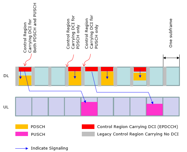
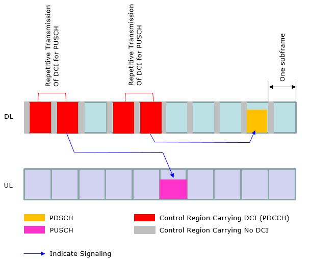
At early LTE (before Rel 10), the operation mode in DCI (Resource Allocation) was pretty simple and straightforward (at least in FDD) as in < Case 1 >. However, as the technology evolves we started setting different variations of DCI operation. Now we have special types of LTE specially designed for IoT/M2M application and DCI operation has been changed even further. In this section, I will try to visualize several typical types of DCI operations as examples just to give you some big picture on how DCI works for PDSCH and PUSCH scheduling.


What kind of information is carried by each DCI ?
The best way to understand this in very detail is to take one example of each of DCI bit string and decode manually based on 3GPP specification. But this section can be a good summary for quick reference. And the DCI decode examples at the end of this page would give you a good/detailed picture of DCI strutures.
Type 0 : A bitmap indicating the resource block groups(RBGs) that are allocated to the scheduled UE. (An RBG is a set of consecutive physical resource blocks(PRBs). This type has following informations
- Flag for format 0/format1A differentiation
- Hoping flag
- Resource block assignment and hopping resource allocation
- New data indicator
- TPC command for scheduled PUSCH
- Cyclic shift for DM RS
- CQI request
- Number of appended zeros to format 0
Type 1 : A bitmap indicating PRBs from a set of PRBs from a subset of resource block groups determined by the system bandwidth.
- Resource allocation header (resource allocation type 0/type 1)
- Resource block assignment
- Modulation and coding scheme
- HARQ process number
- New data indicator
- Redundancy version
- TPC command for PUCCH
Type 2 : A set of contiguously allocated physical or virtual resource blocks. The allocations vary from a single PRB upto the maximum number of PRBs spanning the system bandwidth.
What determines a DCI Format for the specific situation ?
There are two major factors to determine a DCI format for a specific situation as follows :
i) RNTI Type
ii) Transmission Mode
This means that you cannot change only one of these parameters arbitrarily and you always have to think of the relationships among these when you change one of these parameters. Otherwise you will spend a long time for troubleshooting -:)
Those tables from 3GPP 36.213 shows the relationships between RNTI Type, Transmission Mode and DCI format. (You would notice that same information (same RNTI type) can have multiple candidates of DCI format. Then, the question is "How network determine which DCI format it has to use at a specific moment ?". In some case, you can find a clear criteria from following table, but some other case the selection criteria is not clear. For example, if you ask "Do I have to use DCI format 1A or 2A when I am using TM3, C-RNTI ?". You may say "Use DCI format 2A in MIMO configuration and use 1 A in non-MIMO configuration". But the answer would not be clear if you ask "What kind of DCI format (1A or 1C) for Paging message (P-RNTI) ?". At least table 7.1-2 does now show any different selection criteria and I haven't found anywhere else in the spec about this selection criteria. In this case, I just ask to several other people who is working on that specific area and trying to draw conclusion by a kind of 'vote'. For this specific case (DCI format for P-RNTI), I got the response saying "There is no clear criteria, it is just upto network on which one to pick".)根据RNTI类型和发射模式来确定DCI格式
< 38.213-v14.6.0 Table 7.1-1: PDCCH and PDSCH configured by SI-RNTI >
| DCI format | Search Space | Transmission scheme of PDSCH corresponding to PDCCH |
| DCI format 1C | Common | If the number of PBCH antenna ports is one, Single-antenna port, port 0 is used , otherwise Transmit diversity . |
| DCI format 1A | Common | If the number of PBCH antenna ports is one, Single-antenna port, port 0 is used , otherwise Transmit diversity . |
< 38.213-v14.6.0 Table 7.1-2: PDCCH and PDSCH configured by P-RNTI >
| DCI format | Search Space | Transmission scheme of PDSCH corresponding to PDCCH |
| DCI format 1C | Common | If the number of PBCH antenna ports is one, Single-antenna port, port 0 is used, otherwise Transmit diversity |
| DCI format 1A | Common | If the number of PBCH antenna ports is one, Single-antenna port, port 0 is used , otherwise Transmit diversity |
< 38.213-v14.6.0 Table 7.1-3: PDCCH and PDSCH configured by RA-RNTI >
| DCI format | Search Space | Transmission scheme of PDSCH corresponding to PDCCH |
| DCI format 1C | Common | If the number of PBCH antenna ports is one, Single-antenna port, port 0 is used , otherwise Transmit diversity |
| DCI format 1A | Common | If the number of PBCH antenna ports is one, Single-antenna port, port 0 is used , otherwise Transmit diversity |
< 38.213-v14.6.0 Table 7.1-5: PDCCH and PDSCH configured by C-RNTI>
| Transmission mode | DCI format | Search Space | Transmission scheme of PDSCH corresponding to PDCCH |
| Mode 1 | DCI format 1A | Common and UE specific by C-RNTI | Single-antenna port, port 0 |
| DCI format 1 | UE specific by C-RNTI | Single-antenna port, port 0 | |
| Mode 2 | DCI format 1A | Common and UE specific by C-RNTI | Transmit Diversity |
| DCI format 1 | UE specific by C-RNTI | Transmit Diversity | |
| Mode 3 | DCI format 1A | Common and UE specific by C-RNTI | Transmit Diversity |
| DCI format 2A | UE specific by C-RNTI | Large delay CDD or Transmit Diversity | |
| Mode 4 | DCI format 1A | Common and UE specific by C-RNTI | Transmit Diversity |
| DCI format 2 | UE specific by C-RNTI | Closed-loop multiplexing or Transmit Diversity | |
| Mode 5 | DCI format 1A | Common and UE specific by C-RNTI | Transmit Diversity |
| DCI format 1D | UE specific by C-RNTI | Multi-user MIMO | |
| Mode 6 | DCI format 1A | Common and UE specific by C-RNTI | Transmit Diversity |
| DCI format 1B | UE specific by C-RNTI | Closed-loop multiplexing using a single transmission layer | |
| Mode 7 | DCI format 1A | Common and UE specific by C-RNTI | If the number of PBCH antenna ports is one, Single-antenna port, port 0 is used , otherwise Transmit diversity |
| DCI format 1 | UE specific by C-RNTI | Single-antenna port, port 5 | |
| Mode 8 | DCI format 1A | Common and UE specific by C-RNTI | If the number of PBCH antenna ports is one, Single-antenna port, port 0 is used , otherwise Transmit diversity |
| DCI format 2B | UE specific by C-RNTI | Dual layer transmission, port 7 and 8 or single-antenna port, port 7 or 8 | |
| Mode 9 | DCI format 1A | Common and UE specific by C-RNTI | Non-MBSFN subframe: If the number of PBCH antenna ports is one, Single-antenna port, port 0 is used, otherwise Transmit diversity |
| DCI format 2C | UE specific by C-RNTI | Transmit diversity, port 7-8, or dual layer transmission port 7-8 , if UE is configured with higher layer parameter semiOpenLoop, up to 8 layer transmission, ports 7-14 otherwise; or single-antenna port, port 7, 8, 11, or 13 if UE is configured with higher layer parameter dmrs-tableAlt, single-antenna port, port 7 or 8 otherwise | |
| Mode 10 | DCI format 1A | Common and UE specific by C-RNTI | Non-MBSFN subframe: If the number of PBCH antenna ports is one, Single-antenna port, port 0 is used, otherwise Transmit diversity |
| DCI format 2D | UE specific by C-RNTI | Transmit diversity, port 7-8, or dual layer transmission port 7-8 , if UE is configured with higher layer parameter semiOpenLoop, up to 8 layer transmission, ports 7-14 otherwise; or single-antenna port, port 7, 8, 11, or 13 if UE is configured with higher layer parameter dmrs-tableAlt, single-antenna port, port 7 or 8 otherwise |
< 38.213-v14.6.0 Table 7.1-7: PDCCH and PDSCH configured by Temporary C-RNTI>
| DCI format | Search Space | Transmission scheme of PDSCH corresponding to PDCCH |
| DCI format 1A | Common and UE specific by C-RNTI | If the number of PBCH antenna port is one, Single-antenna port, port 0 is used , otherwise Transmit diversity |
| DCI format 1 | UE specific by C-RNTI | If the number of PBCH antenna port is one, Single-antenna port, port 0 is used , otherwise Transmit diversity |
Any relations between DCI format and Layer 3 signaling message ?
Yes, there is a relationship. You have to know which DCI format is required for which RRC message. Following tables from 3GPP 36.321 shows the relationship between RNTI and logical channel and you would know which RRC message is carried by which logical channel. So with two step induction, you will figure out the link between RRC message and it's corresponding DCI format.从RRC消息判断出承载的逻辑信道,再根据逻辑信道和RNTI间的关系判断出使用的RNTI,最后结合发射模式确定DCI格式。

For example, if you see the "Security Mode Command" message of section 6.2.2 of 36.331, it says
Signalling radio bearer: SRB1
RLC-SAP: AM
Logical channel: DCCH
Direction: UE to E-UTRAN
If you see the table, you would see this message is using C-RNTI. and you will figure out the possible candiates from table 7.1-5 of 36.213 and if you would have detailed information of the transmission mode, you can pinpoint out exactly which DCI format you have to use for this message for a specific case. Assuming TM mode in this case is TM1 and scheduling is dynamic scheduling, if you see Table 7.1-2 you will figure out that this is using C-RNTI. With this RNTI Type and TM mode, if you see table 7.1-5, this case use DCI Format 1 or DCI Format 1A.
Just for Convenience, I created a table that shows RNTI types and DCI Format that can be used for each RNTI. (You can figure this out by combining the descriptions of various tables in previous section.)

Full Details of Each DCI Contents
A lot of complications resides in the composition (structure) of each DCI Format. This is a huge topic and requires a lot of cross referencess among multiple specification. I would just start with DCI format 0 and I think it would take a couple of weeks to complete this section.
NOTE 1: The structure of each DCI format is defined in 36.212 5.3.3.1 DCI formats but many of the fields in a DCI are defined in many other specifications. I tried to consolidate all the different specifications in this single page, so that you can get all the informations here without opening multiple specifications.
NOTE 2: Most of these tables are based on Release 8 specification. Some of field name might have been changed in later specification.
NOTE 3 : DCI for LTE Advanced is not described here. I wrote a separate pages for DCI for LTE Advanced.
You may see the structure of DCI looks too complicated. However, this would be taken as simple comparing to the procedure through which this DCI information has to go to get transmitted through Antenna. DCI that is described above is MAC layer concept and at least you can decode and understand the meaning of each bit field with relatively small effort. Since this is another huge topic and it is transport/physical layer issue, I described these issues in a couple of different pages as linked below.
The overall flow of channel coding to Resource Eelement mapping process for DCI is described in Physical Layer Channel : Downlink : PDCCH (Physical Download Control Channel)
The location of a PDCCH that carries a DCI (even though it is the exactly identical information) varies at every subframe. The location of the PDCCH is determined by CCE Index at transmitter (eNB). But this CCE index is not informed to the reciever (UE). UE has to figure out the location of PDCCH by blind decoding. This process is described in CCE Index Calculation/PDCCH Decoding/Blind Decoding. 不同子帧承载DCI的PDCCH位置不同。PDCCH位置由ENB的CCE索引决定。但CCE索引没有通知给UE。UE智能通过盲解码找到PDCCH位置。
When UE is trying blind decoding, how many different combinations of possible PDCCH allocation area (Search Space) ? This is described in PDCCH Candidate and Search Space
当UE进行盲检,有多少不同的可能PDCCH分配区域(搜索空间)的组合?
How many physical layer bits (how many Resource Elements) a PDCCH occupy when it is being transmitted ? This is explained in PDCCH Resource Allocation.
If you are not faimilar with the PDCCH allocation unit called CCE and how the REG gets distributed over control channel region. Refer to Resource Allocation and Management Unit
If you want to look in further details at the matlab code level, refer to Matlab :ToolBox : LTE : Downlink : PDCCH. This is not a full detail since it is based on Matlab Toolbox and the implementations of the toolbox function is not open to user, but you would get pretty good understandings of overall transport/physical channel process for DCI.


 5万+
5万+


 被折叠的 条评论
为什么被折叠?
被折叠的 条评论
为什么被折叠?
 到【灌水乐园】发言


