


实验拓扑及要求如下所示: 1、R4为ISP,其上只配置IP地址;R4与其他所直连设备间均使用公有IP;
2、R3-R5、R6、R7为MGRE环境,R3为中心站点;
3、整个OSPF环境IP基于172.16.0.0/16划分;除了R12有两个环回,其他路由器均有一个环回IP
4、所有设备均可访问R4的环回;
5、减少LSA的更新量,加快收敛,保障更新安全;
6、全网可达;
分析:
要完成这种大型实验,最需要的是心平气和一步步来。
实验:
1.配置IP:
最左侧R1:
<Huawei>sys
Enter system view, return user view with Ctrl+Z.
[Huawei]sysname R1
[R1]
Please check whether system data has been changed, and save data in time
Configuration console time out, please press any key to log on
<R1>
<R1>
<R1>
<R1>
<R1>sys
Enter system view, return user view with Ctrl+Z.
[R1]int g0/0/0
[R1-GigabitEthernet0/0/0]ip add 172.16.33.1 24
Apr 16 2024 18:31:21-08:00 R1 %%01IFNET/4/LINK_STATE(l)[0]:The line protocol IP
on the interface GigabitEthernet0/0/0 has entered the UP state.
[R1-GigabitEthernet0/0/0]int l0
[R1-LoopBack0]ip add 172.16.34.1 24
R2:
<Huawei>sys
Enter system view, return user view with Ctrl+Z.
[Huawei]sysname R2
[R2]
Please check whether system data has been changed, and save data in time
Configuration console time out, please press any key to log on
<R2>
<R2>
<R2>sys
Enter system view, return user view with Ctrl+Z.
[R2]int g0/0/0
[R2-GigabitEthernet0/0/0]ip add 172.16.33.2 24
Apr 16 2024 18:33:36-08:00 R2 %%01IFNET/4/LINK_STATE(l)[0]:The line protocol IP
on the interface GigabitEthernet0/0/0 has entered the UP state.
[R2-GigabitEthernet0/0/0]int l0
[R2-LoopBack0]ip add 172.16.35.1 24
R3:
<Huawei>sys
Enter system view, return user view with Ctrl+Z.
[Huawei]sysname R3
[R3]int g0/0/0
[R3-GigabitEthernet0/0/0]ip add 172.16.33.3 24
Apr 16 2024 18:42:57-08:00 R3 %%01IFNET/4/LINK_STATE(l)[0]:The line protocol IP
on the interface GigabitEthernet0/0/0 has entered the UP state.
[R3-GigabitEthernet0/0/0]int l0
[R3-LoopBack0]ip add 172.16.36.1 24
[R3-LoopBack0]int s4/0/0
[R3-Serial4/0/0]ip ad 34.0.0.1 24
区域0:
R4:
<Huawei>sys
Enter system view, return user view with Ctrl+Z.
[Huawei]sysname R4
[R4]int g0/0/0
[R4-GigabitEthernet0/0/0]ip add 47.0.0.1 24
Apr 16 2024 18:46:28-08:00 R4 %%01IFNET/4/LINK_STATE(l)[0]:The line protocol IP
on the interface GigabitEthernet0/0/0 has entered the UP state.
[R4-GigabitEthernet0/0/0]int l0
[R4-LoopBack0]ip add 172.16.2.1 24
[R4-LoopBack0]int s4/0/0
[R4-Serial4/0/0]ip add 34.0.0.2 24
[R4-Serial4/0/0]
Apr 16 2024 18:47:21-08:00 R4 %%01IFNET/4/LINK_STATE(l)[1]:The line protocol PPP
IPCP on the interface Serial4/0/0 has entered the UP state.
[R4-Serial4/0/0]int s4/0/1
[R4-Serial4/0/1]ip add 45.0.0.1 24
[R4-Serial4/0/1]int s3/0/0
[R4-Serial3/0/0]ip add 46.0.0.1 24
R5:
<Huawei>sys
Enter system view, return user view with Ctrl+Z.
[Huawei]sysname R5
[R5]
Please check whether system data has been changed, and save data in time
Configuration console time out, please press any key to log on
<R5>sys
Enter system view, return user view with Ctrl+Z.
[R5]int s4/0/0
[R5-Serial4/0/0]ip add 45.0.0.2 24
[R5-Serial4/0/0]
Apr 16 2024 18:49:35-08:00 R5 %%01IFNET/4/LINK_STATE(l)[0]:The line protocol PPP
IPCP on the interface Serial4/0/0 has entered the UP state.
[R5-Serial4/0/0]int l0
[R5-LoopBack0]ip add 172.16.3.1 24
R6:
<Huawei>sys
Enter system view, return user view with Ctrl+Z.
[Huawei]sysname R6
Please check whether system data has been changed, and save data in time
Configuration console time out, please press any key to log on
<Huawei>sys
Enter system view, return user view with Ctrl+Z.
[Huawei]sysname R6
[R6]int s4/0/0
[R6-Serial4/0/0]ip add 46.0.0.2 24
[R6-Serial4/0/0]
Apr 16 2024 18:51:43-08:00 R6 %%01IFNET/4/LINK_STATE(l)[0]:The line protocol PPP
IPCP on the interface Serial4/0/0 has entered the UP state.
[R6-Serial4/0/0]int g0/0/0
[R6-GigabitEthernet0/0/0]ip add 172.16.65.1 30
Apr 16 2024 18:52:07-08:00 R6 %%01IFNET/4/LINK_STATE(l)[1]:The line protocol IP
on the interface GigabitEthernet0/0/0 has entered the UP state.
[R6-GigabitEthernet0/0/0]int l0
[R6-LoopBack0]ip add 172.16.4.1 24
R7:
<Huawei>sys
Enter system view, return user view with Ctrl+Z.
[Huawei]sysname R7
[R7]
Please check whether system data has been changed, and save data in time
Configuration console time out, please press any key to log on
<R7>sys
Enter system view, return user view with Ctrl+Z.
[R7]int g0/0/0
[R7-GigabitEthernet0/0/0]ip add 47.0.0.2 24
Apr 16 2024 18:54:37-08:00 R7 %%01IFNET/4/LINK_STATE(l)[0]:The line protocol IP
on the interface GigabitEthernet0/0/0 has entered the UP state.
[R7-GigabitEthernet0/0/0]int g0/0/1
[R7-GigabitEthernet0/0/1]ip ad 172.16.97.1 30
Apr 16 2024 18:56:25-08:00 R7 %%01IFNET/4/LINK_STATE(l)[1]:The line protocol IP
on the interface GigabitEthernet0/0/1 has entered the UP state.
[R7-GigabitEthernet0/0/1]intl0
^
Error: Unrecognized command found at '^' position.
[R7-GigabitEthernet0/0/1]int l0
[R7-LoopBack0]ip add 172.16.5.1 24
区域3:
R8:
[R8-GigabitEthernet0/0/1]ip add 172.16.97.5 30
Info: A similar IP subnet already exists. Please verify the current IP subnet de
sign.
[R8-GigabitEthernet0/0/1]
Apr 16 2024 19:09:36-08:00 R8 %%01IFNET/4/LINK_STATE(l)[0]:The line protocol IP
on the interface GigabitEthernet0/0/1 has entered the UP state.
[R8-GigabitEthernet0/0/1]int g0/0/0
[R8-GigabitEthernet0/0/0]ip add 172.16.97.2 30
[R8-GigabitEthernet0/0/0]int l0
[R8-LoopBack0]ip add 172.16.98.1 24
R9:
<R9>sys
Enter system view, return user view with Ctrl+Z.
[R9]int g0/0/0
[R9-GigabitEthernet0/0/0]ip add 172.16.97.6 30
Apr 16 2024 19:16:30-08:00 R9 %%01IFNET/4/LINK_STATE(l)[0]:The line protocol IP
on the interface GigabitEthernet0/0/0 has entered the UP state.
[R9-GigabitEthernet0/0/0]
Apr 16 2024 19:16:30-08:00 R9 ARP/4/ARP_IPCONFLICT_TRAP:OID 16777216.50331648.10
0663296.16777216.67108864.16777216.3674669056.83886080.419430400.2063597568.3355
4432.100663296 ARP detects IP conflict. (IP address=5.97.16.172, Local interface
=GigabitEthernet0/0/0, Local MAC=00e0-fc95-3db6, Local vlan=0, Local CE vlan=0,
Receive interface=GigabitEthernet0/0/0, Receive MAC=00e0-fc0e-2499, Receive vlan
=0, Receive CE vlan=0, IP conflict type=Local IP conflict).
[R9-GigabitEthernet0/0/0]
Apr 16 2024 19:16:30-08:00 R9 %%01ARP/4/ARP_DUPLICATE_IPADDR(l)[1]:Received an A
RP packet with a duplicate IP address from the interface. (IpAddress=5.97.16.172
, InterfaceName=GigabitEthernet0/0/0, MacAddress=00e0-fc0e-2499)
[R9-GigabitEthernet0/0/0]int g0/0/1
[R9-GigabitEthernet0/0/1]ip add 172.16.129.1 30
Apr 16 2024 19:17:11-08:00 R9 %%01IFNET/4/LINK_STATE(l)[2]:The line protocol IP
on the interface GigabitEthernet0/0/1 has entered the UP state.
[R9-GigabitEthernet0/0/1]int l0
[R9-LoopBack0]ip add 171.16.130.1 24
区域4:
R10:
<R10>sys
Enter system view, return user view with Ctrl+Z.
[R10]int g0/0/0
[R10-GigabitEthernet0/0/0]ip add 172.16.129.2 30
Apr 16 2024 19:19:46-08:00 R10 %%01IFNET/4/LINK_STATE(l)[0]:The line protocol IP
on the interface GigabitEthernet0/0/0 has entered the UP state.
[R10-GigabitEthernet0/0/0]int l0
[R10-LoopBack0]ip add 172.16.131.1 24
区域2:
R11:
<R11>sys
Enter system view, return user view with Ctrl+Z.
[R11]int g0/0/0
[R11-GigabitEthernet0/0/0]ip add 172.16.65.2 30
Apr 16 2024 19:21:10-08:00 R11 %%01IFNET/4/LINK_STATE(l)[0]:The line protocol IP
on the interface GigabitEthernet0/0/0 has entered the UP state.
[R11-GigabitEthernet0/0/0]int g0/0/1
[R11-GigabitEthernet0/0/1]ip add 172.16.65.5 30
Apr 16 2024 19:21:24-08:00 R11 %%01IFNET/4/LINK_STATE(l)[1]:The line protocol IP
on the interface GigabitEthernet0/0/1 has entered the UP state.
[R11-GigabitEthernet0/0/1]int l0
[R11-LoopBack0]ip add 172.16.66.1 24
R12:
<R12>sys
Enter system view, return user view with Ctrl+Z.
[R12]int g0/0/0
[R12-GigabitEthernet0/0/0]ip add 172.16.65.6 30
Apr 16 2024 19:22:32-08:00 R12 %%01IFNET/4/LINK_STATE(l)[0]:The line protocol IP
on the interface GigabitEthernet0/0/0 has entered the UP state.
[R12-GigabitEthernet0/0/0]int l0
[R12-LoopBack0]ip add 172.16.160.1 24
[R12-LoopBack0]int l1
[R12-LoopBack1]ip add 172.16.161.1 24
地址到此为止,接下来需要让公私网通,观察由于公网设备极少,故公网通快,先配置公网通:
1.公网通(静态缺省):
R3:[R3]ip route-static 0.0.0.0 0 34.0.0.2
R5:[R5]ip route-static 0.0.0.0 0 45.0.0.1
R6:[R6]ip route-static 0.0.0.0 0 46.0.0.1
R7:[R7]ip route-static 0.0.0.0 0 47.0.0.1
2.私网通(ospf协议):
R1:
[R1]ospf 1 rou
[R1]ospf 1 router-id 1.1.1.1
[R1-ospf-1]a 1
[R1-ospf-1-area-0.0.0.1]net 172.16.32.0 0.0.31.255
R2:
[R2]ospf 1 rou
[R2]ospf 1 router-id 2.2.2.2
Info: The configuration succeeded. You need to restart the OSPF process to valid
ate the new router ID.
[R2-ospf-1]a 1
[R2-ospf-1-area-0.0.0.1]net 172.16.32.0 0.0.31.255
R3:
[R3]ospf 1 rou
[R3]ospf 1 router-id 3.3.3.3
[R3-ospf-1]a 1
[R3-ospf-1-area-0.0.0.1]net 172.16.32.0 0.0.31.255
R5:
[R5]ospf 1 rou
[R5]ospf 1 router-id 5.5.5.5
[R5-ospf-1]a 0
[R5-ospf-1-area-0.0.0.0]net 172.16.0.0 0.0.31.255
R6:
[R6]ospf 1 rou
[R6]ospf 1 router-id 6.6.6.6
[R6-ospf-1]a 0
[R6-ospf-1-area-0.0.0.0]net 172.16.0.0 0.0.31.255
[R6-ospf-1-area-0.0.0.0]q
[R6-ospf-1]q
[R6]ospf 1 rou
[R6]ospf 1 router-id 6.6.6.6
[R6-ospf-1]a 2
[R6-ospf-1-area-0.0.0.2]net 172.16.64.0 0.0.31.255
R7:
[R7]ospf 1 rou
[R7]ospf 1 router-id 7.7.7.7
[R7-ospf-1]a 0
[R7-ospf-1-area-0.0.0.0]net 172.16.0.0 0.0.31.255
[R7]ospf 1
[R7-ospf-1]a 3
[R7-ospf-1-area-0.0.0.3]net 172.16.96.0 0.0.31.255
R8:
[R8]ospf 1 rou
[R8]ospf 1 router-id 8.8.8.8
[R8-ospf-1]a 3
[R8-ospf-1-area-0.0.0.3]net 172.16.96.0 0.0.31.255
R9:
[R9]ospf 1 rou
[R9]ospf 1 router-id 9.9.9.9
[R9-ospf-1]a 3
[R9-ospf-1-area-0.0.0.3]net 172.16.96.0 0.0.31.255
(由于area 4不规则,所以用多线程引入)
[R9]ospf 2 rou
[R9]ospf 2 router-id 9.9.9.9
[R9-ospf-2]a 4
[R9-ospf-2-area-0.0.0.4]net 172.16.128.0 0.0.31.255
R10:
[R10]ospf 2 rou
[R10]ospf 2 router-id 10.10.10.10
[R10-ospf-2]a 4
[R10-ospf-2-area-0.0.0.4]net 172.16.128.0 0.0.31.255
R11:
[R11]ospf 1 rou
[R11]ospf 1 router-id 11.11.11.11
[R11-ospf-1]a 2
[R11-ospf-1-area-0.0.0.2]net 172.16.64.0 0.0.31.255
R12:
[R12]ospf 1 rou
[R12]ospf 1 router-id 12.12.12.12
[R12-ospf-1]a 2
[R12-ospf-1-area-0.0.0.2]net 172.16.64.0 0.0.31.255
[R12-ospf-1]q
[R12]rip 1
[R12-rip-1]v 2
[R12-rip-1]undo s
[R12-rip-1]undo silent-interface
[R12-rip-1]undo summary
[R12-rip-1]net 172.16.0.0
(注意,rip宣告只宣告网络位)
[R12]ospf 1
[R12-ospf-1]imp
[R12-ospf-1]import-route rip
(做路由引入)
这里就已经达成成就--私网区域内通了,让我们选出各私网区域内的一个代表:
area 1-->R1:
area 2-->R11:

area 3-->R8:
 area 4-->R10:
可以看到,在各个小区域内已然完成了通路,那么如何实现全网通呢
接下来就要请MGRE隧道登场了,以R3作为中心站点,其它作为分支站点:
R3:
[R3]int t
[R3]int Tunnel 0/0/0
[R3-Tunnel0/0/0]ip add 172.16.6.1 24
[R3-Tunnel0/0/0]tu
[R3-Tunnel0/0/0]tunnel-protocol gre p
[R3-Tunnel0/0/0]tunnel-protocol gre p2mp
[R3-Tunnel0/0/0]sou
[R3-Tunnel0/0/0]source s4/0/0
Apr 19 2024 18:45:09-08:00 R3 %%01IFNET/4/LINK_STATE(l)[0]:The line protocol IP
on the interface Tunnel0/0/0 has entered the UP state.
[R3-Tunnel0/0/0]nhrp n
[R3-Tunnel0/0/0]nhrp network-id 100
[R3-Tunnel0/0/0]nhrp ent
[R3-Tunnel0/0/0]nhrp entry m
[R3-Tunnel0/0/0]nhrp entry multicast d
[R3-Tunnel0/0/0]nhrp entry multicast dynamic
R5:
[R5]int t0/0/0
[R5-Tunnel0/0/0]ip add 172.16.6.2 24
[R5-Tunnel0/0/0]tu
[R5-Tunnel0/0/0]tunnel-protocol g
[R5-Tunnel0/0/0]tunnel-protocol gre p
[R5-Tunnel0/0/0]tunnel-protocol gre p2mp
[R5-Tunnel0/0/0]sou
[R5-Tunnel0/0/0]source s4/0/0
Apr 19 2024 18:47:00-08:00 R5 %%01IFNET/4/LINK_STATE(l)[0]:The line protocol IP
on the interface Tunnel0/0/0 has entered the UP state.
[R5-Tunnel0/0/0]
[R5-Tunnel0/0/0]nhrp network-id 100
[R5-Tunnel0/0/0]nhrp e
[R5-Tunnel0/0/0]nhrp entry 172.16.6.1 34.0.0.1 r
[R5-Tunnel0/0/0]nhrp entry 172.16.6.1 34.0.0.1 register
R6:
[R6]int t0/0/0
[R6-Tunnel0/0/0]ip add 172.16.6.3 24
[R6-Tunnel0/0/0]tunnel-protocol gre p
[R6-Tunnel0/0/0]tunnel-protocol gre p2mp
[R6-Tunnel0/0/0]source s4/0/0
Apr 19 2024 18:51:41-08:00 R6 %%01IFNET/4/LINK_STATE(l)[0]:The line protocol IP
on the interface Tunnel0/0/0 has entered the UP state.
[R6-Tunnel0/0/0]
[R6-Tunnel0/0/0]nhrp n
[R6-Tunnel0/0/0]nhrp network-id 100
[R6-Tunnel0/0/0]nhrp en
[R6-Tunnel0/0/0]nhrp entry 172.16.6.1 34.0.0.1 r
R7:
[R7]int t0/0/0
[R7-Tunnel0/0/0]ip add 172.16.6.4 24
[R7-Tunnel0/0/0]tu
[R7-Tunnel0/0/0]tunnel-protocol gre p
[R7-Tunnel0/0/0]tunnel-protocol gre p2mp
[R7-Tunnel0/0/0]s
[R7-Tunnel0/0/0]set
[R7-Tunnel0/0/0]shutdown
[R7-Tunnel0/0/0]source g0/0/0
Apr 19 2024 18:55:07-08:00 R7 %%01IFNET/4/LINK_STATE(l)[0]:The line protocol IP
on the interface Tunnel0/0/0 has entered the UP state.
[R7-Tunnel0/0/0]
[R7-Tunnel0/0/0]nhrp n
[R7-Tunnel0/0/0]nhrp network-id 100
[R7-Tunnel0/0/0]nhrp e
[R7-Tunnel0/0/0]nhrp entry 172.16.6.1 34.0.0.1 r
[R7-Tunnel0/0/0]nhrp entry 172.16.6.1 34.0.0.1 register
隧道搭建完毕,接下来应该启动路由协议--------ospf:
R3:
[R3]ospf 1
[R3-ospf-1]dis th
[V200R003C00]
#
ospf 1 router-id 3.3.3.3
area 0.0.0.1
network 172.16.32.0 0.0.31.255
#
return
[R3-ospf-1]a 0
[R3-ospf-1-area-0.0.0.0]net 172.16.6.0 0.0.0.255
R5:
[R5]ospf 1
[R5-ospf-1]a 0
[R5-ospf-1-area-0.0.0.0]net 172.16.6.0 0.0.0.255
[R5-ospf-1-area-0.0.0.0]
R6:
[R6]ospf 1
[R6-ospf-1]a 0
[R6-ospf-1-area-0.0.0.0]net 172.16.6.0 0.0.0.255
[R6-ospf-1-area-0.0.0.0]
R7:
[R7]ospf 1
[R7-ospf-1]a 0
[R7-ospf-1-area-0.0.0.0]net 172.16.6.0 0.0.0.255
[R7-ospf-1-area-0.0.0.0]
然而,由于dr和bdr选举和p2p模式等一系列问题,导致私网之间仍不能相互通信,所以我们需要解决这些个问题:
首先是p2p模式:
将Tunnel接口ospf模式 改为broadcast
R3:
[R3-Tunnel0/0/0]ospf
Apr 19 2024 19:05:44-08:00 R3 %%01OSPF/4/NBR_CHANGE_E(l)[3]:Neighbor changes eve
nt: neighbor status changed. (ProcessId=256, NeighborAddress=2.6.16.172, Neighbo
rEvent=LoadingDone, NeighborPreviousState=Loading, NeighborCurrentState=Full)
[R3-Tunnel0/0/0]ospf n
[R3-Tunnel0/0/0]ospf network-type b
[R3-Tunnel0/0/0]ospf network-type broadcast
R5:
[R5]int t0/0/0
[R5-Tunnel0/0/0]ospf n
[R5-Tunnel0/0/0]ospf network-type b
[R5-Tunnel0/0/0]ospf network-type broadcast
R6:
[R6]int t0/0/0
[R6-Tunnel0/0/0]ospf n
[R6-Tunnel0/0/0]ospf network-type b
[R6-Tunnel0/0/0]ospf network-type broadcast
R7:
[R7]int t0/0/0
[R7-Tunnel0/0/0]ospf n b
于是我们发现,刚才还静悄悄的界面突然被消息轰炸: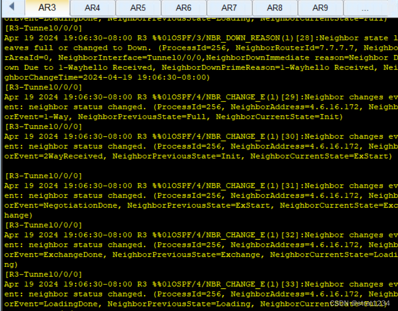

下面是dr和bdr选举混乱:
取消一些站点(分支站点)的选举资格:
[R5]int t0/0/0
[R5-Tunnel0/0/0]ospf dr
[R5-Tunnel0/0/0]ospf dr-priority 0
对R5,R6,R7都像这样配置即可: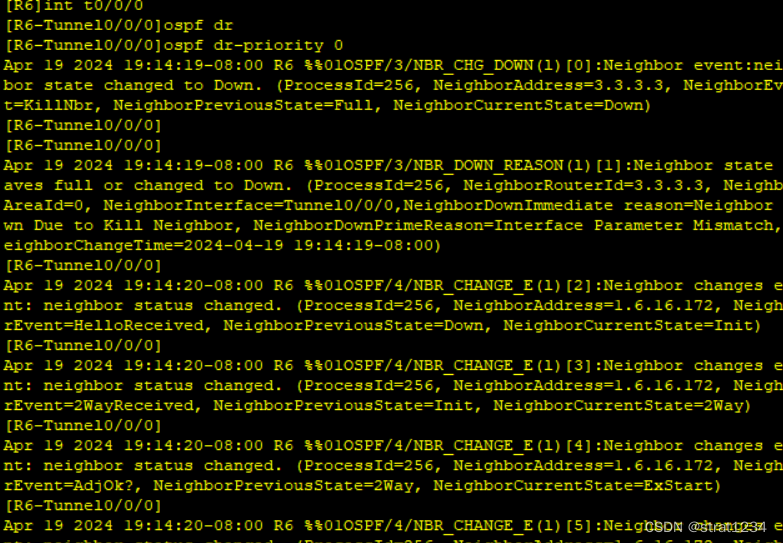
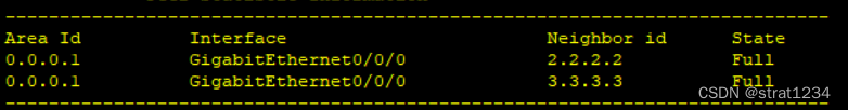
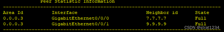
观察一下邻居表(R3):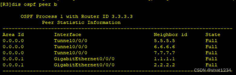
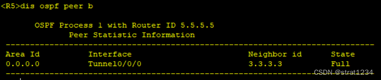
R5(只会和中心站点建联):
观察一下路由表情况(以R1为例):
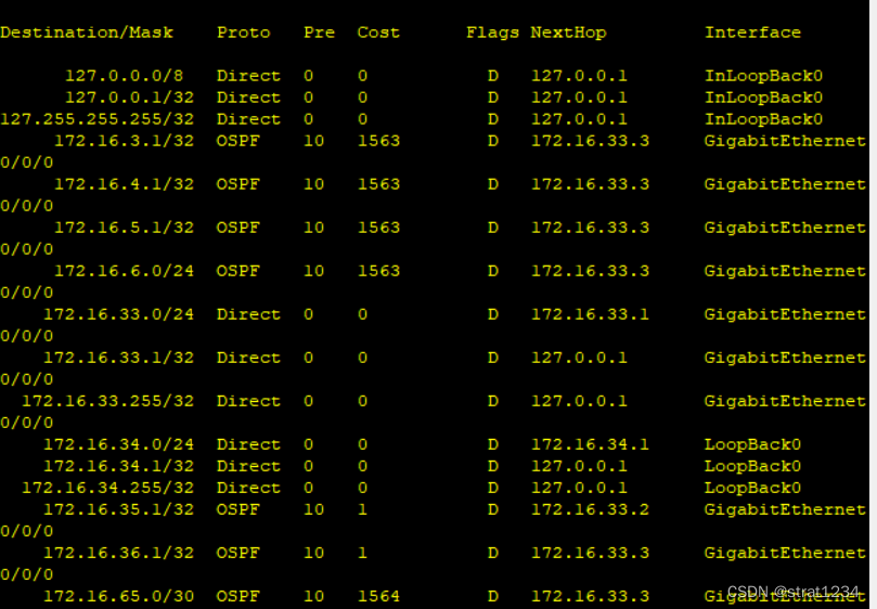
可以看到,基本学习完毕.
但经过观察,我们发现部分路由似乎并未被学习到,这是因为我们并未做路由引入:
在R9上:
[R9]ospf 1
[R9-ospf-1]im
[R9-ospf-1]import-route ospf 2
[R9-ospf-1]q
[R9]ospf 2
[R9-ospf-2]im
[R9-ospf-2]import-route ospf 1
将进程1和进程2互相引入,再次查看:
R1:

R10:
随机ping也可以实现:
接下来是所有设备均可访问R4的环回:
R3:
[R3]acl 2000
[R3-acl-basic-2000]rule pe
[R3-acl-basic-2000]rule permit source 172.16.0.0 0.0.255.255
[R3-acl-basic-2000]q
[R3]
[R3]int s4/0/0
[R3-Serial4/0/0]nat out
[R3-Serial4/0/0]nat outbound 2000
[R3-Serial4/0/0]q
R5:
[R5]acl 2000
[R5-acl-basic-2000]rule p
[R5-acl-basic-2000]rule permit s
[R5-acl-basic-2000]rule permit source 172.16.0.0 0.0.255.255
[R5-acl-basic-2000]q
[R5]int s4/0/0
[R5-Serial4/0/0]nat o
[R5-Serial4/0/0]nat outbound 2000
R6:
[R6]acl 2000
[R6-acl-basic-2000]r
[R6-acl-basic-2000]rule p
[R6-acl-basic-2000]rule permit s
[R6-acl-basic-2000]rule permit source 172.16.0.0 0.0.255.255
[R6-acl-basic-2000]q
[R6]nat o
[R6]nat overlap-address
[R6]int s4/0/0
[R6-Serial4/0/0]nat o
[R6-Serial4/0/0]nat outbound 2000
R7:
[R7]acl 2000
[R7-acl-basic-2000]rule p
[R7-acl-basic-2000]rule permit s
[R7-acl-basic-2000]rule permit source 172.16.0.0 0.0.255.255
[R7-acl-basic-2000]q
[R7]int g0/0/0
[R7-GigabitEthernet0/0/0]nat o
[R7-GigabitEthernet0/0/0]nat outbound 2000
[R7-GigabitEthernet0/0/0]
接下来配置一个缺省,但我们先完成后面的内容
接下来是减少LSA的更新量,做路由聚合:
先做abr聚合:
R3:
[R3]ospf 1
[R3-ospf-1]a 1
[R3-ospf-1-area-0.0.0.1]abr-su
[R3-ospf-1-area-0.0.0.1]abr-summary 172.16.32.0 255.255.224.0
R6:
[R6]ospf 1
[R6-ospf-1]a 2
[R6-ospf-1-area-0.0.0.2]abr-su
[R6-ospf-1-area-0.0.0.2]abr-summary 172.16.64.0 255.255.224.0
R7:
[R7]ospf 1
[R7-ospf-1]a 3
[R7-ospf-1-area-0.0.0.3]abr-su
[R7-ospf-1-area-0.0.0.3]abr-summary 172.16.96.0 255.255.224.0
接下来是域外路由聚合:
R9:
[R9]ospf 1
[R9-ospf-1]asbr-su
[R9-ospf-1]asbr-summary 172.16.128.0 255.255.224.0
R12:
[R12]ospf 1
[R12-ospf-1]asbr-s
[R12-ospf-1]asbr-summary 172.16.160.0 255.255.224.0
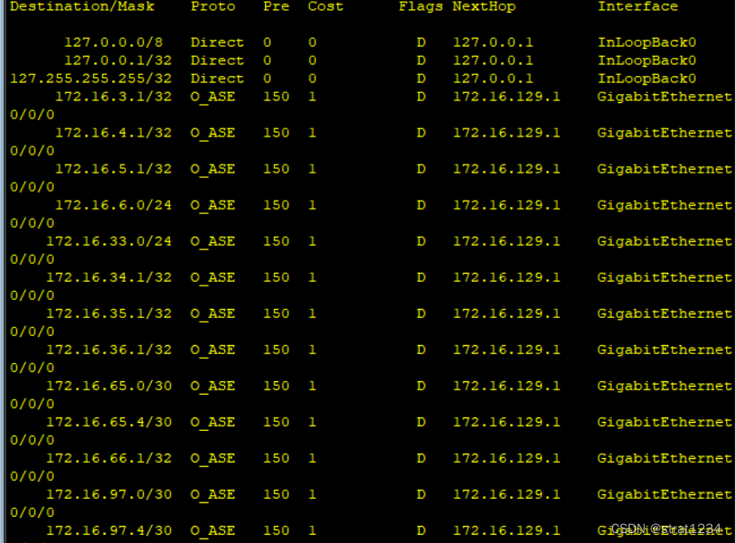
接下来观察新的路由表(R2):
缩减了一部分了,但是不够,接下来我们需要将它们设置成特殊区域:
area 1:
[R3]ospf 1
[R3-ospf-1]a 1
[R3-ospf-1-area-0.0.0.1]stu
[R3-ospf-1-area-0.0.0.1]stub no-s
[R3-ospf-1-area-0.0.0.1]stub no-summary
还有R1和R2也这样配,每个区域中所有路由器都像我写的例子一样
area 2:
[R11]ospf 1
[R11-ospf-1]a 2
[R11-ospf-1-area-0.0.0.2]nssa no-s
area 3:
[R9]ospf 1
[R9-ospf-1]a 3
[R9-ospf-1-area-0.0.0.3]nssa no-s
来观察R1的路由情况:

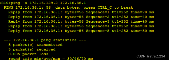
可以观察到表极度精简,它被改编成了一个缺省路由,而前面提过我们仅差一个缺省路由,故让我们ping一下R4环回:
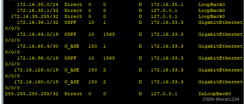
完美解决,但还有一个问题,让我们观察R10:

由于没有相关明细,所以没有其他网段路由,让我们为他配置一条缺省:
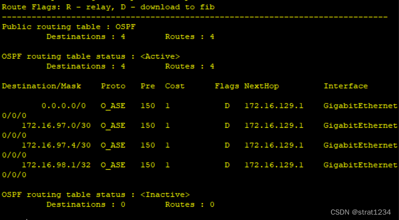
[R9]ospf 2
[R9-ospf-2]d
[R9-ospf-2]default-r
[R9-ospf-2]default-route-advertise
再次观察R10:
接下来是加快网络收敛:
缩短hello时间:
[R1]int g0/0/0
[R1-GigabitEthernet0/0/0]ospf tim
[R1-GigabitEthernet0/0/0]ospf timer hello 5
像这样
让我们看看全网通情况(用R1去ping其它的):

最后保障更新安全(做区域认证):
[R6]ospf 1
[R6-ospf-1]a 2
[R6-ospf-1-area-0.0.0.2]au
[R6-ospf-1-area-0.0.0.2]authentication-mode md5 1 c
[R6-ospf-1-area-0.0.0.2]authentication-mode md5 1 cipher 123
问题被解决,实验结束.


 45
45


 被折叠的 条评论
为什么被折叠?
被折叠的 条评论
为什么被折叠?
 到【灌水乐园】发言


