


前言
上一篇笔记 在VScode上用 EIDE扩展 创建了 AT32F4 系列单片机的工程模板,编译器使用GCC(GNU Arm Embedded Toolchain )。
此模板将在这篇文章中用来开发USART外设。代码由 AT官方的BSP(此处是AT32F421固件库BSP&Pack)
BSP\project\at_start_f421\examples\usart\printf
项目文件修改而来。主要测试AT32F4单片机的串口输出功能。
环境
- VScode ( EIDE + Cortex Debug )
- Open On-Chip Debugger 0.11.0+dev-snapshot
- GCC或者MDK5(后者在测试时用到)
- AT32F421C8T7系统板 & ATLink
- USB < - > TTL 模块
功能描述
PA9引脚复用作USART1外设的TX端,连接CH340模块的RX,用于向主机发送字符串,在主机的串口助手上观察。
为方便观察现象,在发送时使板上的 User LED (连接PC13引脚)闪烁。
代码实现
- main.c:配置系统时钟、AHB&APB时钟。使能GPIO外设的时钟。配置systick寄存器。调用USART1的初始化代码,并进入主循环发送字符串。
/** ************************************************************************** * @file main.c * @version v2.0.5 * @date 2022-04-02 * @brief main program */ #include "at32f421_clock.h" #include "systick.h" #include "usart.h" /** * @brief main function. * @param none * @retval none */ __IO uint32_t time_cnt = 0; int main(void) { system_clock_config(); delay_init(); // LED init gpio_init_type gpio_init_struct; crm_periph_clock_enable(CRM_GPIOC_PERIPH_CLOCK, TRUE); gpio_default_para_init(&gpio_init_struct); gpio_init_struct.gpio_drive_strength = GPIO_DRIVE_STRENGTH_STRONGER; gpio_init_struct.gpio_out_type = GPIO_OUTPUT_PUSH_PULL; gpio_init_struct.gpio_mode = GPIO_MODE_OUTPUT; gpio_init_struct.gpio_pins = GPIO_PINS_13; gpio_init_struct.gpio_pull = GPIO_PULL_NONE; gpio_init(GPIOC, &gpio_init_struct); //USART init uart_print_init(115200); /* output a message on hyperterminal using printf function */ printf("usart printf example: retarget the c library printf function to the usart\r\n"); while (1) { printf("usart printf counter: %u\r\n", time_cnt++); // LED blink GPIOC->odt ^= GPIO_PINS_13; delay_ms(1); GPIOC->odt ^= GPIO_PINS_13; delay_sec(1); } } - systick.c:同上一篇笔记。
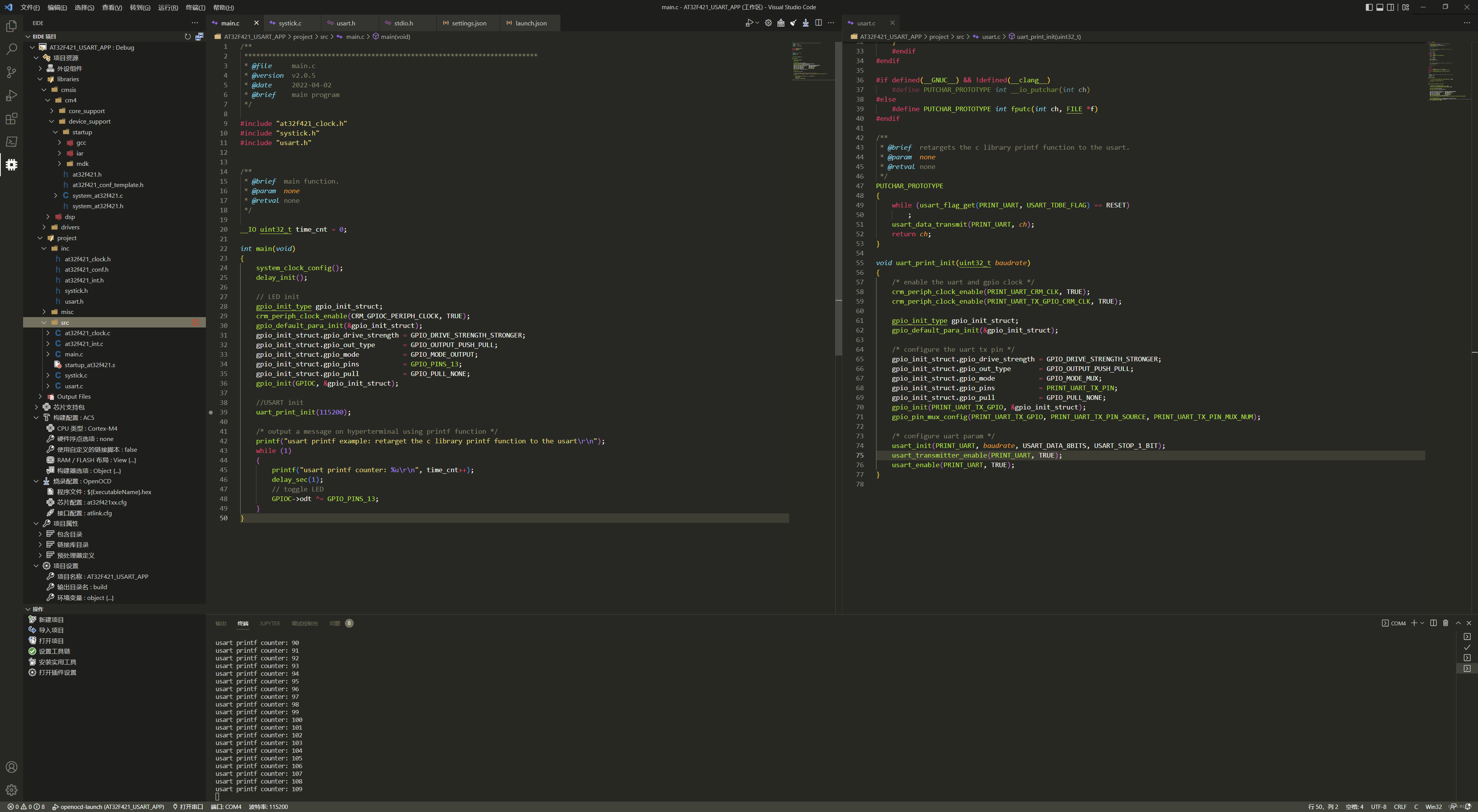
- usart.c:定义了printf()的重定向方法。定义了USART1的初始化函数。
#include "usart.h"

/* support printf function, usemicrolib is unnecessary */
#if (__ARMCC_VERSION > 6000000)
    __asm(".global __use_no_semihosting\n\t");
    void _sys_exit(int x)
    {
        x = x;
    }
    /* __use_no_semihosting was requested, but _ttywrch was */
    void _ttywrch(int ch)
    {
        ch = ch;
    }
    FILE __stdout;
#else
    #ifdef __CC_ARM
    #pragma import(__use_no_semihosting)
    struct __FILE
    {
        int handle;
    };
    FILE __stdout;
    void _sys_exit(int x)
    {
        x = x;
    }
    /* __use_no_semihosting was requested, but _ttywrch was */
    void _ttywrch(int ch)
    {
        ch = ch;
    }
    #endif
#endif

#if defined(__GNUC__) && !defined(__clang__)
    #define PUTCHAR_PROTOTYPE int __io_putchar(int ch)
#else
    #define PUTCHAR_PROTOTYPE int fputc(int ch, FILE *f)
#endif

/**
 * @brief  retargets the c library printf function to the usart.
 * @param  none
 * @retval none
 */
PUTCHAR_PROTOTYPE
{
    while (usart_flag_get(PRINT_UART, USART_TDBE_FLAG) == RESET)
        ;
    usart_data_transmit(PRINT_UART, ch);
    return ch;
}

void uart_print_init(uint32_t baudrate)
{
    /* enable the uart and gpio clock */
    crm_periph_clock_enable(PRINT_UART_CRM_CLK, TRUE);
    crm_periph_clock_enable(PRINT_UART_TX_GPIO_CRM_CLK, TRUE);

    gpio_init_type gpio_init_struct;
    gpio_default_para_init(&gpio_init_struct);

    /* configure the uart tx pin */
    gpio_init_struct.gpio_drive_strength = GPIO_DRIVE_STRENGTH_STRONGER;
    gpio_init_struct.gpio_out_type       = GPIO_OUTPUT_PUSH_PULL;
    gpio_init_struct.gpio_mode           = GPIO_MODE_MUX;
    gpio_init_struct.gpio_pins           = PRINT_UART_TX_PIN;
    gpio_init_struct.gpio_pull           = GPIO_PULL_NONE;
    gpio_init(PRINT_UART_TX_GPIO, &gpio_init_struct);
    gpio_pin_mux_config(PRINT_UART_TX_GPIO, PRINT_UART_TX_PIN_SOURCE, PRINT_UART_TX_PIN_MUX_NUM);

    /* configure uart param */
    usart_init(PRINT_UART, baudrate, USART_DATA_8BITS, USART_STOP_1_BIT);
    usart_transmitter_enable(PRINT_UART, TRUE);
    usart_enable(PRINT_UART, TRUE);
}
但事实证明这里有问题。
具体而言,在GCC编译器下,prinft()底层由__write()实现。AT官方的example在重定向时只定义到int __io_putchar(int ch),编译是没有任何问题的:
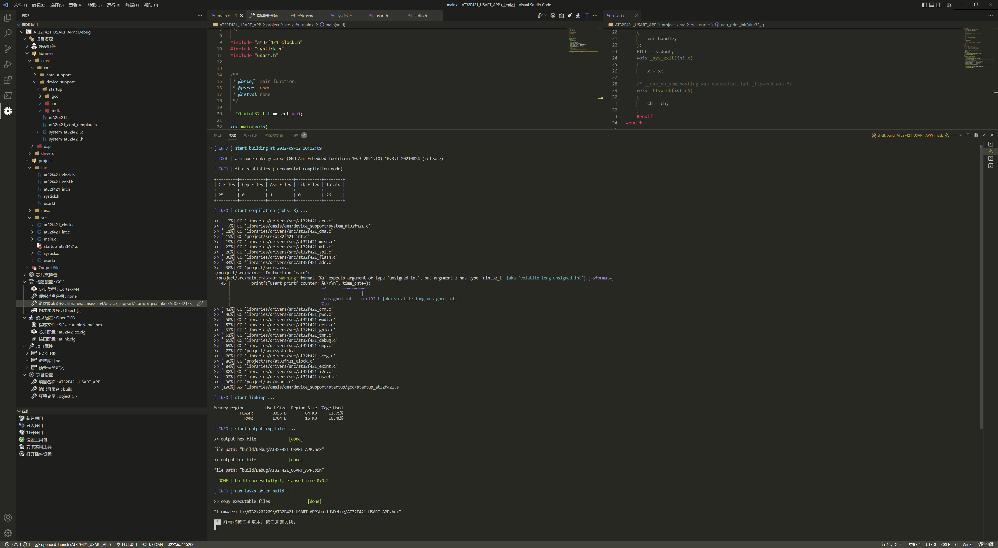
但是烧录后,只能看到LED闪烁,串口却没有收到任何数据(PA9引脚始终为高电平)。
为了测试问题是否来自硬件和BSP库代码,我使用AC5重新编译了项目文件(注意:不同的编译器应使用不同的startup.s文件,并且gcc编译器还应指定scatterFile.ld文件),结果串口成功收到数据:
由此证明问题出在使用gcc编译器时BSP库代码中,在STM32用gcc编译printf重定向到串口 - 知乎 (zhihu.com) 中找到了解决方案。
解决方案
重新定义了_write()函数。修改后的 usart.c:
#include "usart.h"

/* support printf function, usemicrolib is unnecessary */
#if (__ARMCC_VERSION > 6000000)
    __asm(".global __use_no_semihosting\n\t");
    void _sys_exit(int x)
    {
        x = x;
    }
    /* __use_no_semihosting was requested, but _ttywrch was */
    void _ttywrch(int ch)
    {
        ch = ch;
    }
    FILE __stdout;
#else
    #ifdef __CC_ARM
    #pragma import(__use_no_semihosting)
    struct __FILE
    {
        int handle;
    };
    FILE __stdout;
    void _sys_exit(int x)
    {
        x = x;
    }
    /* __use_no_semihosting was requested, but _ttywrch was */
    void _ttywrch(int ch)
    {
        ch = ch;
    }
    #endif
#endif

#if defined(__GNUC__) && !defined(__clang__)
    #define PUTCHAR_PROTOTYPE int __io_putchar(int ch)
#else
    #define PUTCHAR_PROTOTYPE int fputc(int ch, FILE *f)
#endif

/**
 * @brief  retargets the c library printf function to the usart.
 * @param  none
 * @retval none
 */
PUTCHAR_PROTOTYPE
{
    while (usart_flag_get(PRINT_UART, USART_TDBE_FLAG) == RESET)
        ;
    usart_data_transmit(PRINT_UART, ch);
    return ch;
}
// 重写 _write()
int _write(int fd, char *pBuffer, int size)
{
    for (int i = 0; i < size; i++)
    {
        __io_putchar(*pBuffer++);
    }
    return size;
}

void uart_print_init(uint32_t baudrate)
{
    /* enable the uart and gpio clock */
    crm_periph_clock_enable(PRINT_UART_CRM_CLK, TRUE);
    crm_periph_clock_enable(PRINT_UART_TX_GPIO_CRM_CLK, TRUE);

    gpio_init_type gpio_init_struct;
    gpio_default_para_init(&gpio_init_struct);

    /* configure the uart tx pin */
    gpio_init_struct.gpio_drive_strength = GPIO_DRIVE_STRENGTH_STRONGER;
    gpio_init_struct.gpio_out_type       = GPIO_OUTPUT_PUSH_PULL;
    gpio_init_struct.gpio_mode           = GPIO_MODE_MUX;
    gpio_init_struct.gpio_pins           = PRINT_UART_TX_PIN;
    gpio_init_struct.gpio_pull           = GPIO_PULL_NONE;
    gpio_init(PRINT_UART_TX_GPIO, &gpio_init_struct);
    gpio_pin_mux_config(PRINT_UART_TX_GPIO, PRINT_UART_TX_PIN_SOURCE, PRINT_UART_TX_PIN_MUX_NUM);

    /* configure uart param */
    usart_init(PRINT_UART, baudrate, USART_DATA_8BITS, USART_STOP_1_BIT);
    usart_transmitter_enable(PRINT_UART, TRUE);
    usart_enable(PRINT_UART, TRUE);
}
再次编译烧录,问题解决。


 6769
6769


 被折叠的 条评论
为什么被折叠?
被折叠的 条评论
为什么被折叠?
 到【灌水乐园】发言


