


目录
前言
在学习了串口数据包添加包头包尾的方法来接收文本数据包后,拜读了一些大佬的文章,发现可以利用USART_SR寄存器的IDLE来检测总线在何时处于空闲状态,这样就可以在利用RXNE中断标志或DMA读取一串数据后知道何时结束这一串数据。
一、RXNE+IDLE方法
1.寄存器简介
(来源于f10xxx参考手册)
RXNE:读数据寄存器非空 (Read data register not empty)
当RDR移位寄存器中的数据被转移到USART_DR寄存器中,该位被硬件置位。如果
USART_CR1寄存器中的RXNEIE为1,则产生中断。对USART_DR的读操作可以将该位清
零。RXNE位也可以通过写入0来清除,只有在多缓存通讯中才推荐这种清除程序。
0:数据没有收到;
1:收到数据,可以读出。
IDLE:监测到总线空闲 (IDLE line detected)
当检测到总线空闲时,该位被硬件置位。如果USART_CR1中的IDLEIE为’1’,则产生中断。由
软件序列清除该位(先读USART_SR,然后读USART_DR)。
0:没有检测到空闲总线;
1:检测到空闲总线。
注意:IDLE位不会再次被置高直到RXNE位被置起(即又检测到一次空闲总线) 。
(这里可以看出退出IDLE的方法是先读USART_SR,然后读USART_DR)。
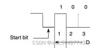
USART收发数据都会有一个起始bit和终止bit,起始bit变为低电平,终止bit升为高电平。空闲时一般为高电平。
2.代码
代码如下
main.c
#include "stm32f10x.h"
#include "usart1.h"

uint8_t Rx_buff[100];    //这里假设存储上限为100
uint16_t Rx_num = 0 ;    //存储计数标志位
uint8_t Rx_done;         //总线空闲中断标志位
int main(void)
{
   Usart1_Init();
   while (1)
	{
   if (Rx_done==1)                //判断是否出现空闲
	 {
		 Rx_done=0;               //标志位清零
		 if (Rx_num >100)         //输入超过存储上限会报错
		 {
			 Serial_Printf("error");
			 Rx_num =0;            //计数位置零
		 }
		 else
		 {
			 Serial_sendarray(Rx_buff,Rx_num);    //串口输出输入的数据,位长由Rx_num确定
		   Rx_num =0;                             //计数位置零
		 }
	 }
  }
}
usart1.c
#include "stm32f10x.h"
#include "stdarg.h"
#include "stdio.h"
uint16_t RXFlag ;
extern uint8_t Rx_buff[100];
extern uint16_t Rx_num  ;
extern uint8_t Rx_done;
void Usart1_Init(void)
{
	RCC_APB2PeriphClockCmd(RCC_APB2Periph_GPIOA, ENABLE);
	RCC_APB2PeriphClockCmd(RCC_APB2Periph_USART1, ENABLE);  //开启时钟

	GPIO_InitTypeDef GPIO_InitStruct;
	GPIO_InitStruct.GPIO_Mode = GPIO_Mode_AF_PP;           //复用推挽输出
	GPIO_InitStruct.GPIO_Pin = GPIO_Pin_9;
	GPIO_InitStruct.GPIO_Speed = GPIO_Speed_50MHz;
	GPIO_Init( GPIOA, &GPIO_InitStruct);

	GPIO_InitStruct.GPIO_Mode = GPIO_Mode_IPU ;            //上拉输入
	GPIO_InitStruct.GPIO_Pin = GPIO_Pin_10;
	GPIO_InitStruct.GPIO_Speed = GPIO_Speed_50MHz;
	GPIO_Init( GPIOA, &GPIO_InitStruct);

	USART_InitTypeDef USART_InitStruct;
	USART_InitStruct.USART_BaudRate = 9600;            //串口波特率9600;
	USART_InitStruct.USART_HardwareFlowControl = USART_HardwareFlowControl_None ;
	USART_InitStruct.USART_Mode = USART_Mode_Tx| USART_Mode_Rx;       //收发均有
	USART_InitStruct.USART_Parity = USART_Parity_No;
	USART_InitStruct.USART_StopBits = USART_StopBits_1;
	USART_InitStruct.USART_WordLength = USART_WordLength_8b;
	USART_Init(USART1,&USART_InitStruct);

	USART_ITConfig(USART1, USART_IT_RXNE, ENABLE);//RXNE中断使能
	USART_ITConfig(USART1, USART_IT_IDLE, ENABLE);//IDLE中断使能

	USART_Cmd(USART1, ENABLE);                 //串口使能

	NVIC_PriorityGroupConfig( NVIC_PriorityGroup_2);
	NVIC_InitTypeDef NVIC_InitStruct;
	NVIC_InitStruct.NVIC_IRQChannel = USART1_IRQn;
	NVIC_InitStruct.NVIC_IRQChannelCmd = ENABLE;
	NVIC_InitStruct.NVIC_IRQChannelPreemptionPriority = 2;
	NVIC_InitStruct.NVIC_IRQChannelSubPriority = 2;
	NVIC_Init(& NVIC_InitStruct);            //NVIC的一系列初始化配置
}
void Serial_senddata(uint16_t byte)
{
	USART_SendData(USART1, byte);
	while(USART_GetFlagStatus( USART1, USART_FLAG_TXE)== RESET);

}                    //调用标准库的USART_SendDataTX,发一字节函数

void Serial_sendarray(uint8_t array[],uint16_t length)
{
	uint16_t i;
	for(i=0 ;i<length ;i++)
	Serial_senddata(array[i] );
}                                              //发送一串已知长度的数组的数据函数

void Serial_sendstring(char *string)
{
	uint16_t i;
	for(i=0 ;string[i]!='\0';i++)
	Serial_senddata(string[i] );
}                                             //发送字符串函数

void Serial_Printf(char *format,...)
{
	char string[100];
	va_list arg;
	va_start (arg,format);
	vsprintf (string ,format,arg);
	va_end(arg);
	Serial_sendstring (string);
}                                            //将格式化的字符串输出到串口函数

void USART1_IRQHandler()
{
	if (USART_GetITStatus(USART1, USART_IT_RXNE)== SET)
	{
		Rx_buff[Rx_num++] = USART_ReceiveData(USART1);       //RXNE读数据寄存器非空,开始读取一串连续的数据,直到空闲出现

	}
	if (USART_GetITStatus(USART1, USART_IT_IDLE)==SET)
	{
		USART1->SR;
		USART1->DR;        //IDLE位清零
		Rx_done=1;         //标志位置1,代表空闲出现,可以读取数据
	}
}
usart1.h
#ifndef __Usart1_H
#define __Usart1_H
void Usart1_Init(void);
void Serial_senddata(uint16_t byte);
void Serial_sendarray(uint8_t *array,uint16_t length);
void Serial_sendstring(char *string);
void Serial_Printf(char *format,...);
#endif
借助串口调试助手,可以看到发送区写一串数据点击发送后,在接收区收到发送的数据,说明每一次发送的数据都存到了Rx_buff[ ]里。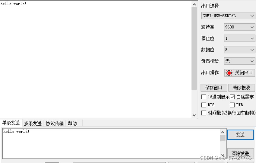
二、DMA+IDLE方法
1.寄存器简介
上面那种接受一位数据触发一次中断的方法虽然可以实现对于不定长数据的接收,而且在CPU处理任务量不大的时候速度和准确率都还可以(起码只开启USART1的RX和TX在串口调试助手上做实验是这样的)。但是感觉用CPU来处理每一次的中断触发任务来实现数据的搬移有些浪费资源。所以这里再给出一种DMA配合串口接收的方法。
(来源于f10xxx参考手册)
DMA简介
直接存储器存取(DMA)用来提供在外设和存储器之间或者存储器和存储器之间的高速数据传输。无须CPU干预,数据可以通过DMA快速地移动,这就节省了CPU的资源来做其他操作。两个DMA控制器有12个通道(DMA1有7个通道,DMA2有5个通道),每个通道专门用来管理来自于一个或多个外设对存储器访问的请求。还有一个仲裁器来协调各个DMA请求的优先权。(DMA2仅存在于大容量产品和互联型产品)。
DMA总线
此总线将DMA的AHB主控接口与总线矩阵相联,总线矩阵协调着CPU的DCode和DMA到SRAM、闪存和外设的访问。
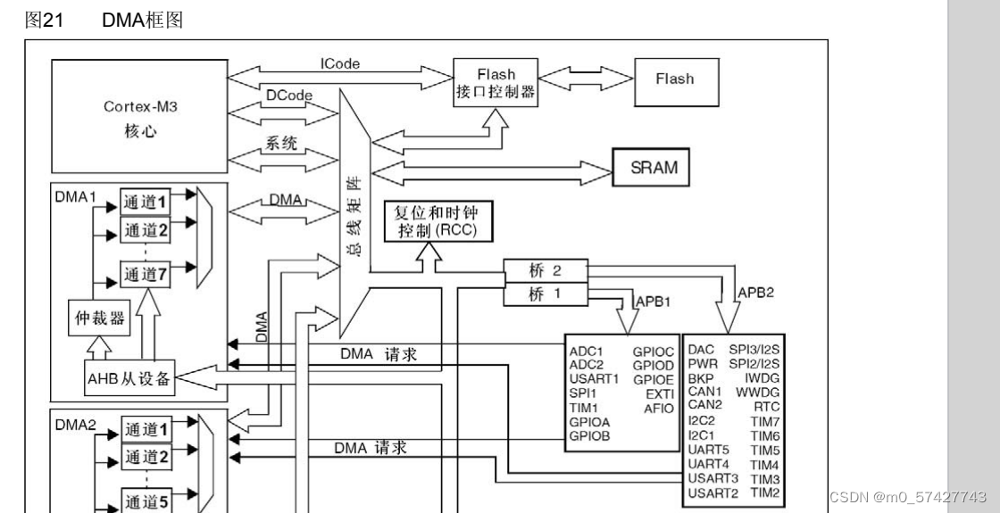
整个输入存储过程可以概括为3步:1.外设向DMA发出请求。2.DMA接受请求开始工作。3.在仲裁器,DMA总线和总线矩阵的协调下,将外设的数据经由AHB总线道通传到专用的7个通道之一的某个通道,最后直接存到SRAM里,不需CPU(系统总线)参与。
2.代码
main.c
#include "stm32f10x.h"                  // Device header
#include "usart1.h"
#include "myDMA.h"

uint16_t DMA_Count;                   //DMA某一次搬运数据大小
uint8_t Serial_Rxflag;                //IDLE中断判断标志
uint8_t Rxdata[200];                  //在SRAM里开辟的存储区,用来存从DMA运来的数据

int main(void)
{
  Usart1_Init();                       //串口初始化
  myDMA_Init((uint32_t)&USART1->DR,(uint32_t)Rxdata);       //DMA初始化+第一次启动
  while(1)
	{
		if (Serial_Rxflag == 1)
		{
			Serial_Rxflag = 0;
			Serial_sendarray(Rxdata,DMA_Count);            //发送数据到串口
		}
	}

}
myDMA.c
#include "stm32f10x.h"                  // Device header

uint16_t myDMA_Size = 200;              //DMA数据最大传输数量为200,即从200开始递减。该值范围0~65535
extern uint16_t DMA_Count ;

void myDMA_Init(uint32_t AddrA,uint32_t AddrB)
{
	RCC_AHBPeriphClockCmd(RCC_AHBPeriph_DMA1, ENABLE);

	DMA_InitTypeDef DMA_InitStruct;
	DMA_InitStruct.DMA_BufferSize = myDMA_Size;
	DMA_InitStruct.DMA_DIR = DMA_DIR_PeripheralSRC;       //指定外设为源端
	DMA_InitStruct.DMA_M2M = DMA_M2M_Disable;            //非存储器到存储器模式
	DMA_InitStruct.DMA_MemoryBaseAddr = AddrB;           //存储器地址
	DMA_InitStruct.DMA_MemoryDataSize = DMA_MemoryDataSize_Byte;     //存储器数据宽度
	DMA_InitStruct.DMA_MemoryInc = DMA_MemoryInc_Enable;      //存储器地址递增
	DMA_InitStruct.DMA_Mode = DMA_Mode_Normal;                //不选择自动重装后循环传输
	DMA_InitStruct.DMA_PeripheralBaseAddr = AddrA;             //外设地址
	DMA_InitStruct.DMA_PeripheralDataSize = DMA_PeripheralDataSize_Byte;    //外设数据宽度
	DMA_InitStruct.DMA_PeripheralInc = DMA_PeripheralInc_Disable;         //外设地址不递增
	DMA_InitStruct.DMA_Priority = DMA_Priority_Medium;        //设通道优先级

	DMA_Init(DMA1_Channel5, &DMA_InitStruct);                //DMA初始化

	DMA_Cmd(DMA1_Channel5, ENABLE);                          //启动DMA
}

void myDMA_Transfer(void)
{
	DMA_Cmd(DMA1_Channel5, DISABLE);
  while (DMA_GetFlagStatus(DMA1_FLAG_TC5==RESET));
  DMA_ClearFlag(DMA1_FLAG_TC5);                            //确保DMA的传输完成
	DMA_Count = myDMA_Size - DMA_GetCurrDataCounter(DMA1_Channel5);     //查看一次转运的数据个数
	DMA_SetCurrDataCounter(DMA1_Channel5, myDMA_Size);         //再次装上BufferSize,必须禁用DMA时才能使用
	DMA_Cmd(DMA1_Channel5, ENABLE);
}
myDMA.h
#ifndef __MYDMA_H
#define __MYDMA_H
void myDMA_Init(uint32_t AddrA,uint32_t AddrB);
void myDMA_Transfer(void);
#endif
usart1.c
#include "stm32f10x.h"                  // Device header
#include "stdio.h"
#include "stdarg.h"
#include "myDMA.h"

extern uint8_t Serial_Rxflag;

void Usart1_Init(void)
{
	RCC_APB2PeriphClockCmd(RCC_APB2Periph_GPIOA, ENABLE);
	RCC_APB2PeriphClockCmd(RCC_APB2Periph_USART1, ENABLE);

	GPIO_InitTypeDef GPIO_InitStruct;
	GPIO_InitStruct.GPIO_Mode = GPIO_Mode_AF_PP;
	GPIO_InitStruct.GPIO_Pin = GPIO_Pin_9;
	GPIO_InitStruct.GPIO_Speed = GPIO_Speed_50MHz;
	GPIO_Init( GPIOA, &GPIO_InitStruct);

	GPIO_InitStruct.GPIO_Mode = GPIO_Mode_IPU ;
	GPIO_InitStruct.GPIO_Pin = GPIO_Pin_10;
	GPIO_InitStruct.GPIO_Speed = GPIO_Speed_50MHz;
	GPIO_Init( GPIOA, &GPIO_InitStruct);

	USART_InitTypeDef USART_InitStruct;
	USART_InitStruct.USART_BaudRate = 9600;
	USART_InitStruct.USART_HardwareFlowControl = USART_HardwareFlowControl_None ;
	USART_InitStruct.USART_Mode = USART_Mode_Tx| USART_Mode_Rx;
	USART_InitStruct.USART_Parity = USART_Parity_No;
	USART_InitStruct.USART_StopBits = USART_StopBits_1;
	USART_InitStruct.USART_WordLength = USART_WordLength_8b;
	USART_Init(USART1,&USART_InitStruct);

	USART_ITConfig(USART1, USART_IT_IDLE, ENABLE);//IDLE中断使能

	USART_DMACmd(USART1, USART_DMAReq_Rx, ENABLE);//DMA使能接收

	USART_Cmd(USART1, ENABLE);

	NVIC_PriorityGroupConfig( NVIC_PriorityGroup_2);
	NVIC_InitTypeDef NVIC_InitStruct;
	NVIC_InitStruct.NVIC_IRQChannel = USART1_IRQn;
	NVIC_InitStruct.NVIC_IRQChannelCmd = ENABLE;
	NVIC_InitStruct.NVIC_IRQChannelPreemptionPriority = 2;
	NVIC_InitStruct.NVIC_IRQChannelSubPriority = 2;
	NVIC_Init(& NVIC_InitStruct);
}
void Serial_senddata(uint16_t byte)
{
	USART_SendData(USART1, byte);
	while(USART_GetFlagStatus( USART1, USART_FLAG_TXE)== RESET);

}

void Serial_sendarray(uint8_t array[],uint16_t length)
{
	uint16_t i;
	for(i=0 ;i<length ;i++)
	Serial_senddata(array[i] );
}

void Serial_sendstring(char *string)
{
	uint16_t i;
	for(i=0 ;string[i]!='\0';i++)
	Serial_senddata(string[i] );
}

void Serial_Printf(char *format,...)
{
	char string[100];
	va_list arg;
	va_start (arg,format);
	vsprintf (string ,format,arg);
	va_end(arg);
	Serial_sendstring (string);
}

void USART1_IRQHandler()
{
	if (USART_GetITStatus(USART1, USART_IT_IDLE)==SET)        //判断总线空闲
	{
		myDMA_Transfer();
		Serial_Rxflag = 1;                //给出空闲标志
		USART1 ->SR;
		USART1 ->DR;          //置零IDLE标志位

	}
}
usart1.h
#ifndef __Usart1_H
#define __Usart1_H
void Usart1_Init(void);
void Serial_senddata(uint16_t byte);
void Serial_sendarray(uint8_t *array,uint16_t length);
void Serial_sendstring(char *string);
void Serial_Printf(char *format,...);
#endif
这里的实验和上面的实验结果类似,一样是用串口调试助手做的测试,不再累述。


 1377
1377


 被折叠的 条评论
为什么被折叠?
被折叠的 条评论
为什么被折叠?
 到【灌水乐园】发言


