


项目要求如下:1.如图下所示蓝色区域为企业内网,红色区域为供应商网络; 2.运行MSTP协议,使得VLAN 10和vlan 20流量负载均衡; 3.SW1为vlan 10的主网关,SW1为vlan 20的备份网关; 4.SW2为vlan 20的主网关,SW2为vlan 10的备份网关; 5.DHCP服务器在vlan 66,网关在SW2上面; 6.企业内网运行静态路由协议或者OSPF路由协议; 7.PC1、PC2自动获取ip地址且可以与PC3互相ping通。
项目拓扑图如下: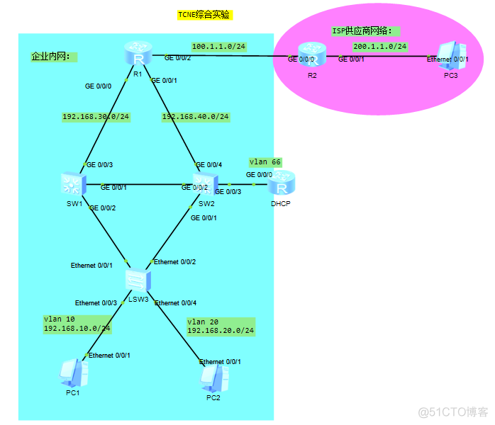
第一步:配置基本网络;SW1配置 sysname SW1 vlan batch 10 20 30 40 66 interface GigabitEthernet 0/0/1 port link-type trunk port trunk allow-pass vlan all interface GigabitEthernet 0/0/2 port link-type trunk port trunk allow-pass vlan all interface GigabitEthernet 0/0/3 port link-type access port default vlan 30 interface Vlanif 30 ip address 192.168.30.2 24 SW2配置 sysname SW2 vlan batch 10 20 30 40 66 interface GigabitEthernet 0/0/1 port link-type trunk port trunk allow-pass vlan all interface GigabitEthernet 0/0/2 port link-type trunk port trunk allow-pass vlan all port link-type access port default vlan 40 interface GigabitEthernet 0/0/3 port link-type access port default vlan 66 interface GigabitEthernet 0/0/4 port link-type access port default vlan 40 interface Vlanif 40 ip address 192.168.40.2 24 SW3配置 sysname SW3 vlan batch 10 20 interface Ethernet0/0/1 port link-type trunk port trunk allow-pass vlan all interface Ethernet0/0/2 port link-type trunk port trunk allow-pass vlan all interface Ethernet0/0/3 port link-type access port default vlan 10 interface Ethernet0/0/4 port link-type access port default vlan 20 R1配置 sysname R1 interface g0/0/0 ip address 192.168.30.1 24 interface g0/0/1 ip address 192.168.40.1 24 interface g0/0/2 ip address 100.1.1.2 24 quit R2配置 sysname R2 interface g0/0/0 ip address 100.1.1.1 24 interface g0/0/1 ip address 200.1.1.254 24 quit
第二步:配置MSTP;配置STP命令 SW1 stp region-configuration region-name ntd instance 10 vlan 10 instance 20 vlan 20 active region-configuration quit stp instance 10 priority 4096 stp instance 20 priority 8192 SW2 stp region-configuration region-name ntd instance 10 vlan 10 instance 20 vlan 20 active region-configuration quit stp instance 10 priority 8192 stp instance 20 priority 4096 SW3 stp region-configuration region-name ntd instance 10 vlan 10 instance 20 vlan 20 active region-configuration quit
第三步:配置VRRP;配置VRRP命令 SW1 interface Vlanif10 ip address 192.168.10.251 255.255.255.0 vrrp vrid 10 virtual-ip 192.168.10.250 vrrp vrid 10 priority 200 interface Vlanif20 ip address 192.168.20.251 255.255.255.0 vrrp vrid 10 virtual-ip 192.168.20.250 interface Vlanif66 ip address 192.168.66.251 255.255.255.0 SW2 interface Vlanif10 ip address 192.168.10.252 255.255.255.0 vrrp vrid 10 virtual-ip 192.168.10.250 interface Vlanif20 ip address 192.168.20.252 255.255.255.0 vrrp vrid 20 virtual-ip 192.168.20.250 vrrp vrid 10 priority 200 interface Vlanif66 ip address 192.168.66.252 255.255.255.0
第四步:配置DHCP;配置DHCP命令 SW1 dhcp enable interface Vlanif 10 dhcp select relay dhcp relay server-ip 192.168.66.250 interface Vlanif 20 dhcp select relay dhcp relay server-ip 192.168.66.250 SW2 dhcp enable interface Vlanif 10 dhcp select relay dhcp relay server-ip 192.168.66.250 interface Vlanif 20 dhcp select relay dhcp relay server-ip 192.168.66.250 DHCP sysname DHCP dhcp enable interface g0/0/0 ip address 192.168.66.250 24 dhcp select global quit ip pool p1 gateway-list 192.168.10.250 network 192.168.10.0 mask 255.255.255.0 excluded-ip-address 192.168.10.251 192.168.10.252 lease day 7 hour 0 minute 0 dns-list 8.8.8.8 ip pool p2 gateway-list 192.168.20.250 network 192.168.20.0 mask 255.255.255.0 excluded-ip-address 192.168.20.251 192.168.20.252 lease day 7 hour 0 minute 0 dns-list 8.8.8.8
第五步:配置OSPF;配置OSPF命令 R1 ospf 1 area 0 network 192.168.30.0 0.0.0.255 network 192.168.40.0 0.0.0.255 ip route-static 0.0.0.0 0.0.0.0 100.1.1.1 SW1 ospf 1 area 0 network 192.168.10.0 0.0.0.255 network 192.168.20.0 0.0.0.255 network 192.168.30.0 0.0.0.255 network 192.168.66.0 0.0.0.255 SW2 ospf 1 area 0 network 192.168.10.0 0.0.0.255 network 192.168.20.0 0.0.0.255 network 192.168.40.0 0.0.0.255 network 192.168.66.0 0.0.0.255 DHCP ospf 1 area 0 network 192.168.66.0 0.0.0.255
第六步:配置NAT;配置NAT命令 acl number 2000
rule 10 permit source 192.168.0.0 0.0.255.255 interface GigabitEthernet0/0/2 nat outbound 2000
最后进行验证:SW1上验证如下: 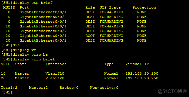
SW2上验证如下:  PC1验证如下:
项目实验完成!!!!


 331
331


 被折叠的 条评论
为什么被折叠?
被折叠的 条评论
为什么被折叠?
 到【灌水乐园】发言


