


 本文围绕电子设计大赛云台题目展开。基础题用一个云台,发挥题用两个云台。最初采用区域法,将openmv分5个区域处理,但存在误差。后改用PID算法,通过求出红点和绿点坐标差值,经公式调参,在摄像头用Python编程求坐标,数据传至32单片机处理,最终达题目要求。
先上视频!
1.首先我们来看看题目
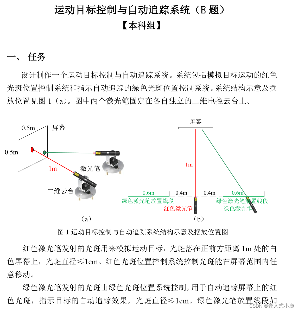
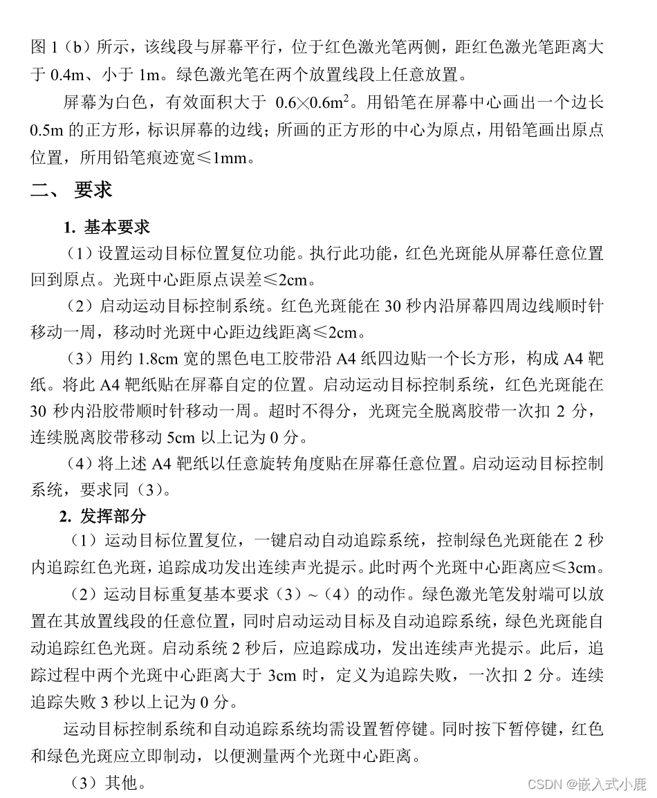
题目还是比较简单明白的,基础题只需要用到一个云台去做这个题目,发挥题需要用到两个云台去解决,首先前几题除了写死没有更好的办法了,我们直接来说一下发挥题怎么做吧,怎么去解决这个问题吧。
做发挥题的时候我是遇到了很多问题的,开始我用的方法是区域法,就是让我识别到的绿点在我的像素中心,刚好我的红点也在我的像素中心。于是我用了这样的方法:将openmv分成5个区域,这样的的话,识别到的点在不同区域就可对应的处理了,将我们寻找到的发送给单片机去处理,不同区域不同的方法解决问题。
IDE(openMV摄像头代码):基于python
# Single Color RGB565 Blob Tracking Example
#
# This example shows off single color RGB565 tracking using the OpenMV Cam.
from pyb import UART#开启串口
import sensor, image, time, math

threshold_index = 0 # 0 for red, 1 for green, 2 for blue

# Color Tracking Thresholds (L Min, L Max, A Min, A Max, B Min, B Max)
# The below thresholds track in general red/green/blue things. You may wish to tune them...
thresholds = [(63, 100, 6, 69, -41, 42)] # generic_blue_thresholds


uart = UART(3, 9600)
x_max = 320
x_min = 0
x_1 = 155 #中心区域左边界
x_2 = 163 #中心区域右边界

y_max = 240
y_min = 0
y_1 = 115 #中心区域上边界
y_2 = 123 #中心区域下边界
flag = 0#位置信息标志


sensor.reset()
sensor.set_pixformat(sensor.RGB565)
sensor.set_framesize(sensor.QVGA)
sensor.skip_frames(time = 2000)
sensor.set_auto_gain(False) # must be turned off for color tracking
sensor.set_auto_whitebal(False) # must be turned off for color tracking
clock = time.clock()

def find_max(blobs):    #定义寻找色块面积最+大的函数
    max_size=0
    for blob in blobs:
        if blob.pixels() > max_size:
            max_blob = blob
            max_size = blob.pixels()
    return max_blob
# Only blobs that with more pixels than "pixel_threshold" and more area than "area_threshold" are
# returned by "find_blobs" below. Change "pixels_threshold" and "area_threshold" if you change the
# camera resolution. "merge=True" merges all overlapping blobs in the image.

while(True):
    clock.tick()
    img = sensor.snapshot()
    for blob in img.find_blobs([thresholds[threshold_index]], area_threshold=50, pixels_threshold=300, area_threshold=200, merge=True):
        # These values depend on the blob not being circular - otherwise they will be shaky.
        if blob.elongation() > 0.5:
            img.draw_edges(blob.min_corners(), color=(255,0,0))
            img.draw_line(blob.major_axis_line(), color=(0,255,0))
            img.draw_line(blob.minor_axis_line(), color=(0,0,255))
        # These values are stable all the time.
        img.draw_rectangle(blob.rect())
        img.draw_cross(blob.cx(), blob.cy())#坐标数据
        # Note - the blob rotation is unique to 0-180 only.

        img.draw_keypoints([(blob.cx(), blob.cy(), int(math.degrees(blob.rotation())))], size=20)


        if blob.cx()>= x_min  and blob.cx() <= 160 and\
            blob.cy() >= 120 and blob.cy() <= y_max :
                flag = 1
        if blob.cx()>=160 and blob.cx() <= x_max and\
            blob.cy() >=120 and blob.cy() <= y_max :
                flag = 2
        if blob.cx()>= x_min and blob.cx() <= 160 and \
            blob.cy() >= y_min and blob.cy() <= 120 :
                flag = 3
        if blob.cx()>= 160 and blob.cx() <= x_max and \
            blob.cy() >= y_min and blob.cy() <= 120 :
                flag = 4
        if blob.cx()>= x_1 and blob.cx() <= x_2 and\
            blob.cy() >= y_1 and blob.cy() <=y_2 :
                flag = 5
        output_str="%d" %flag #方式1
        print('you send:',output_str)
        #time.sleep(0.02)
        uart.write('@'+output_str+'\r\n')
这个方法的32端代码,我用的是C8T6的最小系统去作为我们的主控制的,代码如下:
串口端接受数据包:(状态机)
//文本数据包处理格式
void USART1_IRQHandler(void)
{
	static uint8_t RxState = 0;
	static uint8_t pRxPacket = 0;
	if (USART_GetITStatus(USART1, USART_IT_RXNE) == SET)
	{
		uint8_t RxData = USART_ReceiveData(USART1);

		if (RxState == 0)
		{
			if (RxData == '@' && Serial_RxFlag == 0)
			{
				RxState = 1;
				pRxPacket = 0;
			}
		}
		else if (RxState == 1)
		{
			if (RxData == '\r')
			{
				RxState = 2;
			}
			else
			{
//				strncpy(&Serial_RxPacket[pRxPacket],RxData,1);
				Serial_RxPacket = RxData;
//				pRxPacket ++;
			}
		}
		else if (RxState == 2)
		{
			if (RxData == '\n')
			{
				RxState = 0;
//				Serial_RxPacket[pRxPacket] = '\0';
				Serial_RxFlag = 1;
			}
		}

		USART_ClearITPendingBit(USART1, USART_IT_RXNE);
	}
}
对串口数据进行处理,根据识别到的点不同位置,让舵机去运动:
Where_Addr=Serial_RxPacket-48;
			OLED_ShowNum(4,10,Where_Addr,1);
			switch(Where_Addr)
			{
				case  1:
					{
						AngleY--;
						AngleX++;
					}
					break;
				case  2:
					{
						AngleY--;
						AngleX--;
					}
					break;
				case  3:
					{
						AngleY++;
						AngleX++;
					}
					break;
				case  4:
					{
						AngleY++;
						AngleX--;
					}
					break;
			    case  5:
					{
						been_on();
						LED1_Turn();
						Delay_ms(50);
					}break;

			}
方法修改:
但是这样做有很多弊端,题目要求我们在距离60cm,但是60cm,虽然在了像素中间,但是是斜的,误差很大,无法达到题目要求,这时候我们只能用PID算法来做这个题目了,让他们两个点在像素上无限接近,最后达到题目要求:但是去和用pid算法呢???
这里我们求出红点和绿色点的坐标位置,然后最差值通过pid算法的公式带进去,分别进行pid进行调参,最后到达稳定状态;
在摄像头方面的编程,我们用python进行将两个点的坐标求出来,然后通过串口将数据发送到32单片机进行处理:
import sensor, image, time,lcd,machine
from machine import UART
from fpioa_manager import fm

red_threshold   = (60, 98, 5, 127, 113, -128)
blue_threshold   = (55, 99, -18, -1, 4, 11)#(83, 58, -95, -1, 92, -51)#(65, 100, -113, 102, 3, 71)#(100, 60, -25, 106, 2, 3)

lcd.init()
sensor.reset() # Initialize the camera sensor.
sensor.set_pixformat(sensor.RGB565) # use RGB565.
sensor.set_framesize(sensor.QVGA) # use QQVGA for speed.
sensor.skip_frames(10) # Let new settings take affect.
sensor.set_auto_whitebal(False) # turn this off.
clock = time.clock() # Tracks FPS.
sensor.set_auto_gain(False)
lcd.rotation(2)

#映射UART2的两个引脚

fm.register(0, fm.fpioa.UART1_RX, force=True)  #GPIO0
fm.register(1, fm.fpioa.UART1_TX, force=True)  #GPIO1

#初始化串口,返回调用句柄
uart_A = UART(UART.UART1, 115200, 8, 0, 1)

def find_max(blobs):   #找到最大色块
    max_size = 0
    for blob in blobs:
        if blob.pixels() > max_size:
            max_blob=blob
            max_size = blob.pixels()
    return max_blob

while(True):
    img = sensor.snapshot() # 截取并返回一张图片

    blobs = img.find_blobs([red_threshold])
    blobs2 = img.find_blobs([blue_threshold])
    if blobs:
        if blobs2:
            max_blob=find_max(blobs)#红色色块
            max_blob2=find_max(blobs2)#绿色色块
            img.draw_rectangle(max_blob.cx()-10,max_blob.cy()-10,20,20)  #传入识别到的最大图块的x,y,w,h
            img.draw_rectangle(max_blob2.cx()-10,max_blob2.cy()-10,20,20)  #传入识别到的最大图块的x,y,w,h
            img.draw_cross(max_blob.cx(), max_blob.cy()) #在中心点画十字
            img.draw_cross(max_blob2.cx(), max_blob2.cy()) #在中心点画十字

            output_XY="@%d,%d$%d&%d#" % (max_blob.cx(),max_blob.cy(),max_blob2.cx(),max_blob2.cy())   #以@为开头,逗号分割,#号结尾,发送字符串,由单片机处理得到目标位置中心坐标

            uart_A.write(output_XY)   #传出数据
            print(output_XY)

    lcd.display(img)
32端的代码:
串口中断对数据包处理:
//获取数据包
void USART1_IRQHandler(void)    //发送可变包长字符
{
	static uint8_t RxState = 0;   //定义静态变量表示状态位,根据不同状态位进行不同操作
	static uint8_t pRxPacket = 0;  //表示发送的数据到第几个
	Rx_Config=0;
	if (USART_GetITStatus(USART1, USART_IT_RXNE) == SET)
	{
		uint8_t RxData = USART_ReceiveData(USART1);

		if (RxState == 0)
		{
			if (RxData == '@')  //判断是否为起始位@同时判断
			{
				RxState = 1;   // 起始位判断成功后将给RxState置1
				pRxPacket = 0;
			}
		}
		else if (RxState == 1)
		{
			if (RxData == '#')  //优先判断是否为第一位结束位
			{

				Serial_RxPacket[pRxPacket] = '\0';
				RxState = 0;
				pRxPacket = 0;
				//设计结束标志位
				Rx_Config=1;

			}
			else
			{
				Serial_RxPacket[pRxPacket] = RxData;  //将接收到的字符存到数组
				pRxPacket ++;
			}
		}
		USART_ClearITPendingBit(USART1, USART_IT_RXNE);
	}
}
首先我们设计了定时器中断,没隔一段时间发生中断去处理pid进行舵机的控制:
#include "stm32f10x.h"                  // Device header

//内部时钟

void Timer_Init(void)
{
	RCC_APB1PeriphClockCmd(RCC_APB1Periph_TIM3, ENABLE);   //开启APB1上的tim3时钟控制

	//TIM_InternalClockConfig(TIM3);     //设置内部时钟TIM3

	TIM_TimeBaseInitTypeDef TIM_TimeBaseInitStructure;    //定义开启TIM时钟接口体,并配置参数
	TIM_TimeBaseStructInit(&TIM_TimeBaseInitStructure);   //给未定义的结构体初始值
	TIM_TimeBaseInitStructure.TIM_ClockDivision = TIM_CKD_DIV1;    //选择时钟分频方式(滤波器)
	TIM_TimeBaseInitStructure.TIM_CounterMode = TIM_CounterMode_Up;   //计数方式:向上计数
	TIM_TimeBaseInitStructure.TIM_Period = 2000 - 1;    //ARR自动重装器值设置
	TIM_TimeBaseInitStructure.TIM_Prescaler = 720 - 1;   //PSC预分频值设置
	TIM_TimeBaseInitStructure.TIM_RepetitionCounter = 0;   //高级定时器中的
	TIM_TimeBaseInit(TIM3, &TIM_TimeBaseInitStructure);   //初始化定时器

	TIM_ClearFlag(TIM3, TIM_FLAG_Update);   //清除TIM2复位后生成更新事件以
											//重新加载预分频器
											//和
											//重复计数器立即值

	TIM_ITConfig(TIM3, TIM_IT_Update, ENABLE);   //给TIM3中断控制使能

	NVIC_PriorityGroupConfig(NVIC_PriorityGroup_2);    //选择优先级分组方式

	NVIC_InitTypeDef NVIC_InitStructure;    //定义NVIC结构体并赋值
	NVIC_InitStructure.NVIC_IRQChannel = TIM3_IRQn;    //选择TIM2通道
	NVIC_InitStructure.NVIC_IRQChannelCmd = ENABLE;    //给所选的通道使能
	NVIC_InitStructure.NVIC_IRQChannelPreemptionPriority = 3;    //赋值抢占优先级
	NVIC_InitStructure.NVIC_IRQChannelSubPriority = 3;    //赋值响应优先级
	NVIC_Init(&NVIC_InitStructure);    //定义NVIC

//	TIM_Cmd(TIM3, ENABLE);   //使能TIM3外设
}
在pid方面我们独一数据包将进行处理,处理数据包,获取每个点的坐标,然后求出差值,用pid算法进行调参数,控制pwm占空比
float PID_KP_x =0.45;  //0.6
float PID_KI_x =0.065;	//0.07
float PID_KD_x =0.0;


float PID_KP_y =0.45;  //0.45
float PID_KI_y =0.034; //0.05
float PID_KD_y =0.0;

extern char Serial_RxPacket[40];

char Data_x[10];
char Data_y[10];

char DataBlue_x[10];
char DataBlue_y[10];

int16_t Data_xx;
int16_t Data_yy;

int16_t DataBlue_xx;
int16_t DataBlue_yy;

extern int Trace_Flag;//追踪标志位
/******************位置式****************/
/*******************速度环控制 - 位置式****************/
int16_t Servo_PID_x(int16_t Error)  //传入误差
{
	static int16_t Error_last, Error_difference , Error_All;
	//静态变量储存,上次误差,上次误差与本次误差差值,误差累积

	int16_t Differential;      //返回的最终速度

	Error_difference = Error - Error_last;        //本次误差 - 上次误差

	Error_All += Error;     //误差累计

	if(Error_All >= 6000)        //积分限幅
	{
		Error_All =  6000;
	}
	if(Error_All <= -6000)
	{
		Error_All = -6000;
	}
	//位置式PID,速度闭环
	Differential = PID_KP_x*Error + PID_KI_x * Error_All + PID_KD_x * Error_difference;
	Error_last = Error;     //储存上次误差

	return Differential;
}

int16_t Servo_PID_y(int16_t Error)  //传入误差
{
	static int16_t Error_last, Error_difference , Error_All;
	//静态变量储存,上次误差,上次误差与本次误差差值,误差累积

	int16_t Differential;      //返回的最终速度

	Error_difference = Error - Error_last;        //本次误差 - 上次误差

	Error_All += Error;     //误差累计

	if(Error_All >= 6000)        //积分限幅
	{
		Error_All =  6000;
	}
	if(Error_All <= -6000)
	{
		Error_All = -6000;
	}
	//位置式PID,速度闭环
	Differential = PID_KP_y*Error + PID_KI_y * Error_All + PID_KD_y * Error_difference;
	Error_last = Error;     //储存上次误差

	return Differential;
}

/****************** 数据包解析函数 *******************/
//数据包的处理
//截取数据
void analysis(void)
{
	uint8_t n = 0;
	uint8_t s = 0;

	uint8_t n2 = 0;
	uint8_t s2 = 0;
	 uint8_t i=0;

	while(Serial_RxPacket[i] != ',')
	{
		++i;

	}//得到数据长度

	for(n=0;n<i;n++)//存入数据
	{
		Data_x[n] = Serial_RxPacket[n];
	}
	Data_x[i] = '\0';//数据结束符号
	Data_xx = atoi(Data_x);


	n = i;
	do
	{
		++i;
	}
	while(Serial_RxPacket[i] != '$');

	for(n+=1;n<i;n++)
	{
		Data_y[s] = Serial_RxPacket[n];
		s+=1;
	}
	Data_y[s] = '\0';
	Data_yy = atoi(Data_y); //将接收到的字符数字转换成10进制数

	n = i;
	do
	{
		++i;
	}
	while(Serial_RxPacket[i] != '&');//
	for(n+=1;n<i;n++)
	{
		DataBlue_x[n2] = Serial_RxPacket[n];
		n2+=1;
	}
	DataBlue_x[n2] = '\0';
	DataBlue_xx = atoi(DataBlue_x); //将接收到的字符数字转换成10进制数


	n = i;
	do
	{
		++i;
	}
	while(Serial_RxPacket[i] != '\0');///

	for(n+=1;n<i;n++)
	{
		DataBlue_y[s2] = Serial_RxPacket[n];
		s2+=1;
	}
	DataBlue_y[s2] = '\0';
	DataBlue_yy = atoi(DataBlue_y); //将接收到的字符数字转换成10进制数


	i = 0;
}

void TIM3_IRQHandler(void)
{

	int16_t Error_x;  //定义误差
	int16_t Error_y;
	int16_t PWM_x;   //定义经过PID后的PWM
	int16_t PWM_y;

	if (TIM_GetITStatus(TIM3, TIM_IT_Update) == SET)
	{

		analysis();


		Error_x =DataBlue_xx - Data_xx;  //计算误差
		Error_y =DataBlue_yy - Data_yy;

		if(Error_x>0&&Error_x<8)
		{
			Error_x = 0;
		}
		else if(Error_x<0 && Error_x>-8)
		{
			Error_x = 0;
		}
		else if(Error_y>0&&Error_y<8)
		{
			Error_y = 0;
		}
		else if(Error_y<0 && Error_y>-8)
		{
			Error_y = 0;
		}
		if(Error_y ==0&&Error_x == 0)//表示到得了识别点,距离达到要求了
		{

			been_on();//蜂鸣器响

			LED2_ON();//led亮
			//关闭定时器
			//设计结束标志位
			Trace_Flag=0;

		}

		PWM_x = Servo_PID_x(Error_x);  //计算PID控制后的PWM
		PWM_y = Servo_PID_y(Error_y);

		PWM_SetCompare1(1500 + PWM_x); //舵机角度控制  下面的舵机   x轴
		PWM_SetCompare2(1500 + PWM_y); //舵机角度控制  上面的舵机   y轴

		TIM_ClearITPendingBit(TIM3, TIM_IT_Update);
	}
}
最终我们达到了题目的要求,四天三夜电子设计大赛真的学到了很多!


 1万+
1万+

 被折叠的 条评论
为什么被折叠?
被折叠的 条评论
为什么被折叠?
 到【灌水乐园】发言


