


分析
分出内网和外网,对内网做出IP规划,配置路由器,用dhcp获取pc1、pc2IP地址。内网全部互通,用ospf宣告单区域,给R2、R3、R4写缺省到R5,R5为边界路由器做默认路由,实现全网可达,为避免环路,在R5上设置全网段的空接口,R3连接用户需要在接口上设置沉默。在R5上做缺省到ISP和nat,是内网可以访问到外网,实现内网访问isp。在R1上做telnet,其他设备可以通过telnet登录R1,R6若想登录R1,需要在R5G0/0/1接口上做地址映射。
IP子网划分
骨干一条,用户网段五条,192.168.1.0/24 ,借走主机位三位,做网络位,分成8段
192.168.1.000 00000
a.192.168.1.000 00000-000 11111 即192.168.1.0/27 做骨干
再分成八段 000 000 00
1.0/30 r4r5上; 1.4/30 r1r2;
1.8/30 r1r3; 1.12/30 r2r4;
1.16/30 r3r4; 1.20/30 r4r5下;
1.24/30 和1.28/30 预留
b.192.168.1.001 00000-001 11111 即192.168.1.32/27 做R1回环(2个)
分出两段192.168.1.32/28 192.168.1.48/28
c.192.168.1.010 00000-010 11111 即192.168.1.64/27 做R2回环(2个)
分出两段192.168.1.64/28 192.168.1.80/28
d.192.168.1.011 00000-011 11111 即192.168.1.96/27 做R3主机和g0/0/2
e.192.168.1.100 00000-100 11111 即192.168.1.128/27 做R4回环 (2个)
分出两端192.168.1.128/28 192.168.1.144/28
f.192.168.1.101 00000-101 11111 即192.168.1.160/27 做R5回环(1个)
g.192.168.1.110 00000-110 11111 即192.168.1.192/27 预留
h.192.168.1.111 00000-111 11111 即192.168.1.224/27 预留

配置过程
一、配置路由器IP及回环
r1:
[R1]int lo0
[R1-LoopBack0]ip add 192.168.1.33 28
[R1-LoopBack0]q
[R1]int lo1
[R1-LoopBack1]ip add 192.168.1.49 28
[R1-LoopBack1]q
[R1]int g0/0/0
[R1-GigabitEthernet0/0/0]ip add 192.168.1.5 30
Jan 24 2024 00:52:30-08:00 R1 %%01IFNET/4/LINK_STATE(l)[0]:The line protocol IP
on the interface GigabitEthernet0/0/0 has entered the UP state.
[R1-GigabitEthernet0/0/0]int g0/0/1
[R1-GigabitEthernet0/0/1]ip add 192.168.1.9 30
r2:
[R2]int lo0
[R2-LoopBack0]ip add 192.168.1.65 28
[R2-LoopBack0]int lo1
[R2-LoopBack1]ip add 192.168.1.81 28
[R2-LoopBack1]q
[R2]int g0/0/0
[R2-GigabitEthernet0/0/0]ip add 192.168.1.6 30
Jan 24 2024 01:08:43-08:00 R2 %%01IFNET/4/LINK_STATE(l)[2]:The line protocol IP
on the interface GigabitEthernet0/0/0 has entered the UP state.
[R2-GigabitEthernet0/0/0]int g0/0/1
[R2-GigabitEthernet0/0/1]ip add 192.168.1.13 30
[R2-GigabitEthernet0/0/1]
Jan 24 2024 01:09:07-08:00 R2 %%01IFNET/4/LINK_STATE(l)[3]:The line protocol IP
on the interface GigabitEthernet0/0/1 has entered the UP state.
[R2-GigabitEthernet0/0/1]q
[R2]
r3:
[R3]int g0/0/0
[R3-GigabitEthernet0/0/0]ip add 192.168.1.10 30
Jan 24 2024 01:10:35-08:00 R3 %%01IFNET/4/LINK_STATE(l)[0]:The line protocol IP
on the interface GigabitEthernet0/0/0 has entered the UP state.
[R3-GigabitEthernet0/0/0]int g0/0/1
[R3-GigabitEthernet0/0/1]ip add 192.168.1.17 30
Jan 24 2024 01:11:04-08:00 R3 %%01IFNET/4/LINK_STATE(l)[1]:The line protocol IP
on the interface GigabitEthernet0/0/1 has entered the UP state.
[R3-GigabitEthernet0/0/1]int g0/0/2
[R3-GigabitEthernet0/0/2]ip add 192.168.1.97 27
[R3-GigabitEthernet0/0/2]
Jan 24 2024 01:11:49-08:00 R3 %%01IFNET/4/LINK_STATE(l)[2]:The line protocol IP
on the interface GigabitEthernet0/0/2 has entered the UP state.
[R3-GigabitEthernet0/0/2]
r4:
[R4]int lo0
[R4-LoopBack0]ip add 192.168.1.129 28
[R4-LoopBack0]int lo1
[R4-LoopBack1]ip add 192.168.1.145 28
[R4-LoopBack1]q
[R4]int g0/0/0
[R4-GigabitEthernet0/0/0]ip add 192.168.1.14 30
Jan 24 2024 01:15:11-08:00 R4 %%01IFNET/4/LINK_STATE(l)[0]:The line protocol IP
on the interface GigabitEthernet0/0/0 has entered the UP state.
[R4-GigabitEthernet0/0/0]int g0/0/1
[R4-GigabitEthernet0/0/1]ip add 192.168.1.18 30
Jan 24 2024 01:15:38-08:00 R4 %%01IFNET/4/LINK_STATE(l)[1]:The line protocol IP
on the interface GigabitEthernet0/0/1 has entered the UP state.
[R4-GigabitEthernet0/0/1]int g0/0/2
[R4-GigabitEthernet0/0/2]ip add 192.168.1.1 30
[R4-GigabitEthernet0/0/2]
Jan 24 2024 01:16:00-08:00 R4 %%01IFNET/4/LINK_STATE(l)[2]:The line protocol IP
on the interface GigabitEthernet0/0/2 has entered the UP state.
[R4-GigabitEthernet0/0/2]int g4/0/0
[R4-GigabitEthernet4/0/0]ip add 192.168.1.21 30
[R4-GigabitEthernet4/0/0]
Jan 24 2024 01:16:20-08:00 R4 %%01IFNET/4/LINK_STATE(l)[3]:The line protocol IP
on the interface GigabitEthernet4/0/0 has entered the UP state.
[R4-GigabitEthernet4/0/0]q
r5:
[R5]int lo0
[R5-LoopBack0]ip add 192.168.1.161 27
[R5-LoopBack0]q
[R5]int g0/0/0
[R5-GigabitEthernet0/0/0]ip add 192.168.1.2 30
Jan 24 2024 01:18:18-08:00 R5 %%01IFNET/4/LINK_STATE(l)[0]:The line protocol IP
on the interface GigabitEthernet0/0/0 has entered the UP state.
[R5-GigabitEthernet0/0/0]int g0/0/2
[R5-GigabitEthernet0/0/2]ip add 192.168.1.22 30
Jan 24 2024 01:18:37-08:00 R5 %%01IFNET/4/LINK_STATE(l)[1]:The line protocol IP
on the interface GigabitEthernet0/0/2 has entered the UP state.
[R5-GigabitEthernet0/0/2]int g0/0/1
[R5-GigabitEthernet0/0/1]ip add 12.0.0.1 24
[R5-GigabitEthernet0/0/1]
Jan 24 2024 01:19:02-08:00 R5 %%01IFNET/4/LINK_STATE(l)[2]:The line protocol IP
on the interface GigabitEthernet0/0/1 has entered the UP state.
[R5-GigabitEthernet0/0/1]q
[R5]
r6:
[ISP]int lo0
[ISP-LoopBack0]ip add 6.6.6.6 24
[ISP-LoopBack0]q
[ISP]int g0/0/0
[ISP-GigabitEthernet0/0/0]ip add 12.0.0.2 24
Jan 24 2024 01:21:50-08:00 ISP %%01IFNET/4/LINK_STATE(l)[0]:The line protocol IP
 on the interface GigabitEthernet0/0/0 has entered the UP state.
[ISP-GigabitEthernet0/0/0]q
[ISP]
二、R3主机获取IP地址
[R3]dhcp enable
Info: The operation may take a few seconds. Please wait for a moment.done.
[R3]ip pool 1
Info: It's successful to create an IP address pool.
[R3-ip-pool-1]network 192.168.1.96 mask 27
[R3-ip-pool-1]gate 192.168.1.97
[R3-ip-pool-1]q
[R3]int g0/0/2
[R3-GigabitEthernet0/0/2]dhcp select global
[R3-GigabitEthernet0/0/2]q
[R3]


三、内网互通
用ospf宣告
[R1]ospf 1 rou 1.1.1.1
[R1-ospf-1]area 0
[R1-ospf-1-area-0.0.0.0]network 192.168.1.0 0.0.0.255
[R1-ospf-1-area-0.0.0.0]q
[R1-ospf-1]q
[R2]ospf 1 rou 2.2.2.2
[R2-ospf-1]area 0
[R2-ospf-1-area-0.0.0.0]network 192.168.1.0 0.0.0.255
[R2-ospf-1-area-0.0.0.0]q
[R2-ospf-1]
[R3]ospf 1 rou 3.3.3.3
[R3-ospf-1]area 0
[R3-ospf-1-area-0.0.0.0]network 192.168.1.0 0.0.0.255
[R3-ospf-1-area-0.0.0.0]q
[R3-ospf-1]
[R4]ospf 1 rou 4.4.4.4
[R4-ospf-1]area 0
[R4-ospf-1-area-0.0.0.0]network 192.168.1.0 0.0.0.255
[R4-ospf-1-area-0.0.0.0]q
[R5]ospf 1 rou 5.5.5.5
[R5-ospf-1]area 0
[R5-ospf-1-area-0.0.0.0]network 192.168.1.0 0.0.0.255
[R5-ospf-1-area-0.0.0.0]q
宣告好后 查看路由表

此时内部全网可达,我做的是单区域,不可汇总,路由条目较多。
四、沉默接口
由于r3连接主机,所以进行ospf宣告,需要将g0/0/2口设置为沉默接口
[R3]ospf 1
[R3-ospf-1]silent-interface g0/0/2
[R3-ospf-1]q
五、默认路由
r5为边界路由器
[R5]ospf 1
[R5-ospf-1]de
[R5-ospf-1]default-route-ad
[R5-ospf-1]default-route-advertise
[R5-ospf-1]q
六、 空接口
为避免路由环路 在r5上装一个整个网段的空接口
[R5]ip route-static 192.168.1.0 255.255.255.0 null 0
七、连接外网
在r5上做一条缺省到ISP,做nat
[R5]ip route-static 0.0.0.0 0 12.0.0.2

[R5]acl 2000
[R5-acl-basic-2000]rule permit source 192.168.1.0 0.0.0.255
[R5-acl-basic-2000]q
[R5]int g0/0/1
[R5-GigabitEthernet0/0/1]nat outbound 2000
[R5-GigabitEthernet0/0/1]q
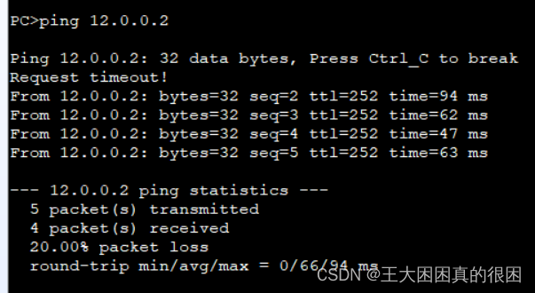
此时内网可以访问ISP 可以ping通外网

八、 正常时通过1000m链路,故障时通过100m链路
内网中r4r5之间的连线有两条,设置浮动静态,通过改变下面的优先级,来使数据优先通过上面链路,下面链路做备用,但是我没有用静态路由进行路由表的宣告。而是用ospf宣告,则我们可以通过修改链路接口开销值来修改链路优先级,通过改变带宽值可以间接改变接口的开销值,即度量值。
正常优先级为10 默认参考带宽为100m,若接口带宽大于参考带宽,cos值为1
计算公式:cost值=参考带宽值➗接口带宽值
将下面链路开销值设大
我们先看原来的路由表

ospf链路总是有两条优先级一样的,观察下一跳,发现两个链路优先级一样,即此时cost值都是1
我们改变下面接口开销值
[R5]int g0/0/2
[R5-GigabitEthernet0/0/2]ospf cost 500
[R5-GigabitEthernet0/0/2]
[R5-GigabitEthernet0/0/2]
[R5-GigabitEthernet0/0/2]
[R5-GigabitEthernet0/0/2]q
[R4]int g4/0/0
[R4-GigabitEthernet4/0/0]ospf cost 500
Jan 24 2024 02:54:36-08:00 R4 %%01RM/4/IPV4_DEFT_RT_CHG(l)[0]:IPV4 default Route
 is changed. (ChangeType=Delete, InstanceId=0, Protocol=OSPF, ExitIf=GigabitEthe
rnet4/0/0, Nexthop=192.168.1.22, Neighbour=0.0.0.0, Preference=2516582400, Label
=NULL, Metric=16777216)
[R4-GigabitEthernet4/0/0]q
开销值改到500(有点大了)
再次查看ospf路由表

优先选择上面链路
此时我们把上面链路接口关掉 再查看一下

关闭了r5的g0/0/0


开销值变得很大了,走了下面的链路

在其他路由器上也有所体现。
九、nat映射 登录telnet R1
在r1上配置telnet
[R1]aaa
[R1-aaa]local-user wang pr
[R1-aaa]local-user wang privilege level 15 pass
[R1-aaa]local-user wang privilege level 15 password ci
[R1-aaa]local-user wang privilege level 15 password cipher 7890
Info: Add a new user.
[R1-aaa]local-user wang service-type telnet
[R1-aaa]q
[R1]user-interface vty 0 4
[R1-ui-vty0-4]au
[R1-ui-vty0-4]authentication-mode aaa
[R1-ui-vty0-4]q
[R1]
测试内网路由器可否登录
 成功。
成功。
再接口上做地址映射
[R5]int g0/0/1
[R5-GigabitEthernet0/0/1]nat server protocol tcp global current-interface telnet
 inside 192.168.1.5 telnet
Warning:The port 23 is well-known port. If you continue it may cause function fa
ilure.
Are you sure to continue?[Y/N]:y
[R5-GigabitEthernet0/0/1]q
 成功!
成功!
总结
本次综合实验也并不难,没有涵盖vlan和acl等一些内容,但也围绕重点内容展开了复习,如最最基础的子网划分、最基础的配置、全网可通可以有静态路由,RIP 和ospf三种方法、连通ISP的nat命令、nat映射、浮动静态(我没有用这个方法修改优先级)。
感谢观看,欢迎指正
拜拜!


 367
367


 被折叠的 条评论
为什么被折叠?
被折叠的 条评论
为什么被折叠?
 到【灌水乐园】发言


