


ACL实验
ACL 简介
ACL(Access Control List,访问控制列表)是网络设备(如路由器、交换机、防火墙)中用于控制数据流进出的规则集合。通过定义允许(Permit)或拒绝(Deny)流量的条件,ACL 是网络安全和流量管理的基础工具。
核心原理
- 规则匹配
- 每条 ACL 规则由 匹配条件 和 处理动作 组成。
- 匹配条件包括:
- 源/目的 IP 地址
- 协议类型(如 TCP、UDP、ICMP)
- 端口号(如 HTTP 80、SSH 22)
- 其他字段(如 TTL、数据包大小)
- 处理动作为
permit(允许)或deny(拒绝)。
- 执行流程
- 数据包按规则顺序逐条匹配,触发首个匹配的规则动作,后续规则被忽略。
- 默认隐式拒绝:若未匹配任何规则,默认丢弃流量(部分设备需显式配置)。
- 方向性
- 入方向(Inbound):控制进入设备接口的流量。
- 出方向(Outbound):控制从设备接口发出的流量。
ACL 类型
| 类型 | 匹配条件 | 典型应用 |
|---|---|---|
| 标准 ACL | 仅源 IP 地址 | 粗粒度控制(如限制子网访问) |
| 扩展 ACL | 源/目的 IP、协议、端口等 | 精细控制(如允许 HTTP 但拒绝 FTP) |
| 命名 ACL | 支持标准/扩展功能,规则可命名管理 | 提升可读性与维护性 |
优点与缺点
| 优点 | 缺点 |
|---|---|
| 1. 灵活控制:支持基于五元组的细粒度策略。 | 1. 配置复杂:规则顺序敏感,易因逻辑错误失效。 |
| 2. 基础安全屏障:防止未授权访问(如屏蔽恶意 IP)。 | 2. 静态规则:无法动态适应新型攻击(如 DDoS)。 |
| 3. 提升网络性能:过滤无用流量(如广播风暴)。 | 3. 性能开销:长列表可能降低设备转发效率。 |
| 4. 兼容性广:几乎所有网络设备均支持 ACL。 | 4. 无状态性:无法跟踪连接状态(需结合其他技术)。 |
应用场景
- 流量过滤
- 例:禁止内部网络访问外部危险端口(如 Telnet 23)。
- 安全策略
- 例:仅允许管理 IP 访问设备 SSH 服务。
- 服务质量(QoS)
- 例:标记 VoIP 流量(端口 5060)为高优先级。
- NAT 与路由控制
- 例:指定特定流量进行地址转换。
配置示例(Cisco 扩展 ACL)
BASH! 创建 ACL 101,允许 HTTP 流量但拒绝 FTP
access-list 101 permit tcp any any eq 80
access-list 101 deny tcp any any eq 21
access-list 101 deny tcp any any eq 20
access-list 101 permit ip any any  ! 允许其他流量

! 将 ACL 101 应用至接口入方向
interface GigabitEthernet0/0
 ip access-group 101 in
注意事项
- 规则顺序优化:高频匹配规则应置于列表顶端。
- 日志记录:可通过
log参数记录被拒绝的流量。 - 测试验证:部署前建议在非生产环境验证规则逻辑。
ACL 是网络安全的基石,结合防火墙、IDS 等工具可构建多层次防御体系。
实验拓扑
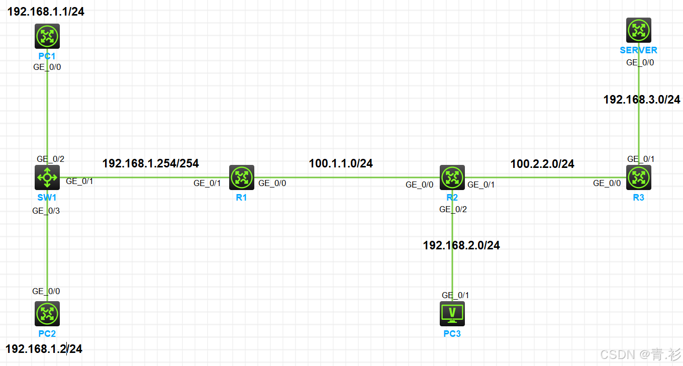
实验需求
1.按照图示配置IP地址
2.全网路由互通
3.在SERVER1上配置开启TELNET和FTP服务
4.配置ACL实现如下效果
1)192.168.1.0/24网段不允许访问192.168.2.0/24网段,要求使用基本ACL实现
2)PC1可以访问SERVER1的TELNET服务,但不能访问FTP服务
3)PC2可以访问SERVER1的FTP服务,但不能访问TELNET服务
4)192.168.2.0/24网段不允许访问SERVER1,要求通过高级ACL实现
实验步骤
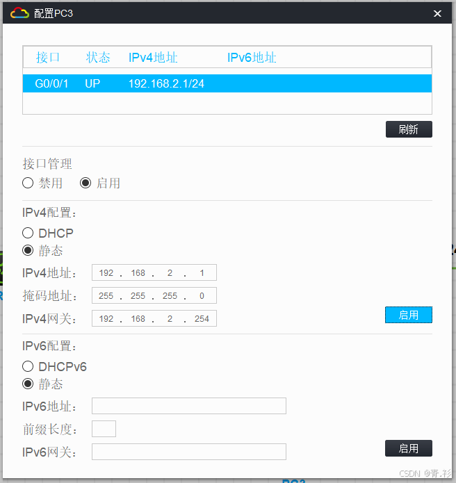
1.配置ip地址
在pc3上
在PC1上
<H3C>system-view
System View: return to User View with Ctrl+Z.
[H3C]sysname PC1
[PC1]int g0/0
[PC1-GigabitEthernet0/0]ip addd
[PC1-GigabitEthernet0/0]ip addd=
[PC1-GigabitEthernet0/0]ip add
[PC1-GigabitEthernet0/0]ip address 192.168.1.1 24
[PC1-GigabitEthernet0/0]display ip int
[PC1-GigabitEthernet0/0]display ip interface brief
*down: administratively down
(s): spoofing  (l): loopback
Interface           Physical Protocol IP address/Mask    VPN instance Description
GE0/0               up       up       192.168.1.1/24     --           --
GE0/1               down     down     --                 --           --
GE0/2               down     down     --                 --           --
GE5/0               down     down     --                 --           --
GE5/1               down     down     --                 --           --
GE6/0               down     down     --                 --           --
GE6/1               down     down     --                 --           --
Ser1/0              down     down     --                 --           --
Ser2/0              down     down     --                 --           --
Ser3/0              down     down     --                 --           --
Ser4/0              down     down     --                 --           --
[PC1-GigabitEthernet0/0]qu
[PC1]ip route-static 0.0.0.0 0 192.168.1.254		//配置默认路由

在PC2上
<H3C>system-view
System View: return to User View with Ctrl+Z.
[H3C]sysname PC2
[PC2]int g0/0
[PC2-GigabitEthernet0/0]ip add
[PC2-GigabitEthernet0/0]ip address 192.168.1.2 24
[PC2-GigabitEthernet0/0]display ip int
[PC2-GigabitEthernet0/0]display ip interface brief
*down: administratively down
(s): spoofing  (l): loopback
Interface           Physical Protocol IP address/Mask    VPN instance Description
GE0/0               up       up       192.168.1.2/24     --           --
GE0/1               down     down     --                 --           --
GE0/2               down     down     --                 --           --
GE5/0               down     down     --                 --           --
GE5/1               down     down     --                 --           --
GE6/0               down     down     --                 --           --
GE6/1               down     down     --                 --           --
Ser1/0              down     down     --                 --           --
Ser2/0              down     down     --                 --           --
Ser3/0              down     down     --                 --           --
Ser4/0              down     down     --                 --           --
[PC2-GigabitEthernet0/0]qu
[PC2]ip route-static 0.0.0.0 0 192.168.1.254		//默认路由
[PC2]

在R1上
<H3C>system-view
System View: return to User View with Ctrl+Z.
[H3C]sysname R1
[R1]int g0/0
[R1-GigabitEthernet0/0]ip address 100.1.1.1 24
[R1-GigabitEthernet0/0]int g0/1
[R1-GigabitEthernet0/1]ip address 192.168.1.254 24
[R1-GigabitEthernet0/1]qu
[R1]display ip interface brief
*down: administratively down
(s): spoofing  (l): loopback
Interface           Physical Protocol IP address/Mask    VPN instance Description
GE0/0               up       up       100.1.1.1/24        --           --
GE0/1               up       up       192.168.1.254/24   --           --
GE0/2               down     down     --                 --           --
GE5/0               down     down     --                 --           --
GE5/1               down     down     --                 --           --
GE6/0               down     down     --                 --           --
GE6/1               down     down     --                 --           --
Ser1/0              down     down     --                 --           --
Ser2/0              down     down     --                 --           --
Ser3/0              down     down     --                 --           --
Ser4/0              down     down     --                 --           --
[R1]

在R2上
<H3C>system-view
System View: return to User View with Ctrl+Z.
[H3C]sysname R2
[R2]int g0/0
[R2-GigabitEthernet0/0]ip address 100.1.1.2 24
[R2-GigabitEthernet0/0]int g0/1
[R2-GigabitEthernet0/1]ip address 100.2.2.2 24
[R2-GigabitEthernet0/1]int g0/2
[R2-GigabitEthernet0/2]ip address 192.168.2.254 24
[R2-GigabitEthernet0/2]display ip interface brief
*down: administratively down
(s): spoofing  (l): loopback
Interface           Physical Protocol IP address/Mask    VPN instance Description
GE0/0               up       up       100.1.1.2/24       --           --
GE0/1               up       up       100.2.2.2/24       --           --
GE0/2               down     down     192.168.2.254/24   --           --
GE5/0               down     down     --                 --           --
GE5/1               down     down     --                 --           --
GE6/0               down     down     --                 --           --
GE6/1               down     down     --                 --           --
Ser1/0              down     down     --                 --           --
Ser2/0              down     down     --                 --           --
Ser3/0              down     down     --                 --           --
Ser4/0              down     down     --                 --           --
[R2-GigabitEthernet0/2]

在R3上
<H3C>system-view
System View: return to User View with Ctrl+Z.
[H3C]sysname R3
[R3]int g0/0
[R3-GigabitEthernet0/0]ip address 10.2.2.3 24
[R3-GigabitEthernet0/0]int g0/1
[R3-GigabitEthernet0/1]ip address 192.168.3.3 24
[R3-GigabitEthernet0/1]display ip interface brief
*down: administratively down
(s): spoofing  (l): loopback
Interface           Physical Protocol IP address/Mask    VPN instance Description
GE0/0               up       up       100.2.2.3/24        --           --
GE0/1               up       up       192.168.3.3/24     --           --
GE0/2               down     down     --                 --           --
GE5/0               down     down     --                 --           --
GE5/1               down     down     --                 --           --
GE6/0               down     down     --                 --           --
GE6/1               down     down     --                 --           --
Ser1/0              down     down     --                 --           --
Ser2/0              down     down     --                 --           --
Ser3/0              down     down     --                 --           --
Ser4/0              down     down     --                 --           --
[R3-GigabitEthernet0/1]

在SERVER上
<H3C>system-view
System View: return to User View with Ctrl+Z.
[H3C]sysname SERVER
[SERVER]int g0/0
[SERVER-GigabitEthernet0/0]ip add
[SERVER-GigabitEthernet0/0]ip address 192.168.3.1 24
[SERVER-GigabitEthernet0/0]qu
[SERVER]ip route-static 0.0.0.0 0 192.168.3.3			//配置默认路由
[SERVER]
2.R1,R2,R3上配置OSPF使全网路由互通
在R1上
[R1]int LoopBack 0						//进入环回口
[R1-LoopBack0]ip address 1.1.1.1 32		//配置本地环回地址
[R1-LoopBack0]qu
[R1]ospf 1 router-id 1.1.1.1			//配置ospf
[R1-ospf-1]area 0						//区域0
[R1-ospf-1-area-0.0.0.0]network 192.168.1.0 0.0.0.255		//	宣告网段
[R1-ospf-1-area-0.0.0.0]network 100.1.1.0 0.0.0.255
[R1-ospf-1-area-0.0.0.0]network 1.1.1.1 0.0.0.0
[R1-ospf-1-area-0.0.0.0]display this
#
 area 0.0.0.0
  network 1.1.1.1 0.0.0.0
  network 100.1.1.0 0.0.0.255
  network 192.168.1.0 0.0.0.255
#
return
[R1-GigabitEthernet0/0]%Mar 20 10:58:50:872 2025 R1 OSPF/5/OSPF_NBR_CHG: OSPF 1 Neighbor 100.1.1.2(GigabitEthernet0/0) changed from LOADING to FULL.

在R2上
[R2]int LoopBack 0
[R2-LoopBack0]ip address 2.2.2.2 32
[R2-LoopBack0]qu
[R2]ospf 1 rou
[R2]ospf 1 router-id 2.2.2.2
[R2-ospf-1]area 0
[R2-ospf-1-area-0.0.0.0]network 100.1.1.0 0.0.0.255
[R2-ospf-1-area-0.0.0.0]network 100.2.2.0 0.0.0.255
[R2-ospf-1-area-0.0.0.0]network 2.2.2.2 0.0.0.0
[R2-ospf-1-area-0.0.0.0]network 192.168.2.0 0.0.0.255
[R2-ospf-1-area-0.0.0.0]display this
#
 area 0.0.0.0
  network 2.2.2.2 0.0.0.0
  network 100.1.1.0 0.0.0.255
  network 100.2.2.0 0.0.0.255
  network 192.168.2.0 0.0.0.255
#
return
[R2-ospf-1-area-0.0.0.0]%Mar 20 10:58:50:609 2025 R2 OSPF/5/OSPF_NBR_CHG: OSPF 1 Neighbor 100.1.1.1(GigabitEthernet0/0) changed from LOADING to FULL.

在R3上
[R3]int LoopBack 0
[R3-LoopBack0]ip add
[R3-LoopBack0]ip address 3.3.3.3 32
[R3-LoopBack0]qu
[R3]ospf 1 rou
[R3]ospf 1 router-id 3.3.3.3
[R3-ospf-1]area 0
[R3-ospf-1-area-0.0.0.0]network 3.3.3.3 0.0.0.0
[R3-ospf-1-area-0.0.0.0]network 100.2.2.0 0.0.0.255
[R3-ospf-1-area-0.0.0.0]network 192.168.3.0 0.0.0.255
[R3-ospf-1-area-0.0.0.0]display this
#
 area 0.0.0.0
  network 3.3.3.3 0.0.0.0
  network 100.2.2.0 0.0.0.255
  network 192.168.3.0 0.0.0.255
#
return
[R3-GigabitEthernet0/0]%Mar 20 11:00:15:380 2025 R3 OSPF/5/OSPF_NBR_CHG: OSPF 1 Neighbor 100.2.2.2(GigabitEthernet0/0) changed from LOADING to FULL.
测试连通性
在PC1上 ping SERVER
[PC1]ping 192.168.3.1
Ping 192.168.3.1 (192.168.3.1): 56 data bytes, press CTRL+C to break
56 bytes from 192.168.3.1: icmp_seq=0 ttl=252 time=2.387 ms
56 bytes from 192.168.3.1: icmp_seq=1 ttl=252 time=1.942 ms
56 bytes from 192.168.3.1: icmp_seq=2 ttl=252 time=2.636 ms
56 bytes from 192.168.3.1: icmp_seq=3 ttl=252 time=2.027 ms
56 bytes from 192.168.3.1: icmp_seq=4 ttl=252 time=2.064 ms

--- Ping statistics for 192.168.3.1 ---
5 packet(s) transmitted, 5 packet(s) received, 0.0% packet loss
round-trip min/avg/max/std-dev = 1.942/2.211/2.636/0.261 ms
[PC1]%Mar 20 11:02:37:515 2025 PC1 PING/6/PING_STATISTICS: Ping statistics for 192.168.3.1: 5 packet(s) transmitted, 5 packet(s) received, 0.0% packet loss, round-trip min/avg/max/std-dev = 1.942/2.211/2.636/0.261 ms.
3.在SERVER上配置开启TELNET和FTP服务
在SERVER上
[SERVER]telnet server enable					//开启telnet服务
[SERVER]ftp server enable						//开启ftp服务
[SERVER]local-user ftx class manage 			//创建提供给telnet的本地管理用户
New local user added.
[SERVER-luser-manage-ftx]password simple admin@12345		//配置用户名密码
[SERVER-luser-manage-ftx]service-type telnet 				//将服务类型设为telnet
[SERVER-luser-manage-ftx]authorization-attribute user-role level-15	//设置用户登录级别为15级
[SERVER-luser-manage-ftx]qu
[SERVER]local-user dxw class manage 		//创建提供给ftp的本地管理用户
New local user added.
[SERVER-luser-manage-dxw]password simple admin@54321		//配置用户名密码
[SERVER-luser-manage-dxw]service-type ftp					//将服务类型设为ftp
[SERVER-luser-manage-dxw]authorization-attribute user-role level-15	//设置用户登录级别为15级
[SERVER-luser-manage-dxw]qu
[SERVER]user-interface vty 0 4				//设置同时在线人数5人
[SERVER-line-vty0-4]authentication-mode scheme 		//设置认证模式为scheme
[SERVER-line-vty0-4]user-role level-15				//再次配置用户登录级别为15级
[SERVER-line-vty0-4]

注:user-role network-admin 设置用户权限  network-admin 为最高权限
测试
测试telnet服务
<PC1>telnet 192.168.3.1
Trying 192.168.3.1 ...
Press CTRL+K to abort
Connected to 192.168.3.1 ...

******************************************************************************
* Copyright (c) 2004-2021 New H3C Technologies Co., Ltd. All rights reserved.*
* Without the owner's prior written consent,                                 *
* no decompiling or reverse-engineering shall be allowed.                    *
******************************************************************************

Login: ftx
Password:
<SERVER>sys
System View: return to User View with Ctrl+Z.
[SERVER]display users
  Idx  Line     Idle       Time              Pid     Type
  0    CON 0    00:00:09   Mar 20 11:10:49   10961
+ 66   VTY 0    00:00:00   Mar 20 11:22:46   10971   TEL

Following are more details.
VTY 0   :
        User name: ftx
        Location: 192.168.1.1
 +    : Current operation user.
 F    : Current operation user works in async mode.
[SERVER]

测试ftp服务
<PC1>ftp 192.168.3.1
Press CTRL+C to abort.
Connected to 192.168.3.1 (192.168.3.1).
220 FTP service ready.
User (192.168.3.1:(none)): dxw
331 Password required for dxw.
Password:
230 User logged in.
Remote system type is UNIX.
Using binary mode to transfer files.
ftp> dir
227 Entering Passive Mode (192,168,3,1,62,127)
150 Accepted data connection
drwxrwxrwx    2 0          0                4096 Mar 20 09:40 diagfile
-rwxrwxrwx    1 0          0               43136 Mar 20 09:40 licbackup
-rwxrwxrwx    1 0          0               43136 Mar 20 09:40 licnormal
drwxrwxrwx    2 0          0                4096 Mar 20 09:40 logfile
-rwxrwxrwx    1 0          0                   0 Mar 20 09:40 msr36-cmw710-boot-r0424p22.bin
-rwxrwxrwx    1 0          0                   0 Mar 20 09:40 msr36-cmw710-system-r0424p22.bin
drwxrwxrwx    2 0          0                4096 Mar 20 09:40 seclog
226 7 matches total
ftp>
4.192.168.1.0/24网段不允许访问192.168.2.0/24网段,要求使用基本ACL实现
在R2上
[R2]acl basic 2000				//配置基本ACL
[R2-acl-ipv4-basic-2000]rule deny source 192.168.1.0 0.0.0.255 //拒绝192.168.1.0网段通过
[R2-acl-ipv4-basic-2000]int g0/2
[R2-GigabitEthernet0/2]packet-filter 2000 outbound 			//绑定出接口
[R2-GigabitEthernet0/2]display this
#
interface GigabitEthernet0/2
 port link-mode route
 combo enable copper
 ip address 192.168.2.254 255.255.255.0
 packet-filter 2000 outbound
#
return
[R2-GigabitEthernet0/2]
测试
<PC1>ping 192.168.2.1
Ping 192.168.2.1 (192.168.2.1): 56 data bytes, press CTRL+C to break
Request time out
Request time out
Request time out
Request time out
Request time out

--- Ping statistics for 192.168.2.1 ---
5 packet(s) transmitted, 0 packet(s) received, 100.0% packet loss
<PC1>%Mar 20 11:34:50:903 2025 PC1 PING/6/PING_STATISTICS: Ping statistics for 192.168.2.1: 5 packet(s) transmitted, 0 packet(s) received, 100.0% packet loss.

<PC2>%Mar 20 11:34:48:530 2025 PC2 SHELL/5/SHELL_LOGIN: Console logged in from con0.

<PC2>
<PC2>ping 192.168.2.1
Ping 192.168.2.1 (192.168.2.1): 56 data bytes, press CTRL+C to break
Request time out
Request time out
Request time out
Request time out
Request time out

--- Ping statistics for 192.168.2.1 ---
5 packet(s) transmitted, 0 packet(s) received, 100.0% packet loss
<PC2>%Mar 20 11:35:03:196 2025 PC2 PING/6/PING_STATISTICS: Ping statistics for 192.168.2.1: 5 packet(s) transmitted, 0 packet(s) received, 100.0% packet loss.
5.PC1可以访问SERVER1的TELNET服务,但不能访问FTP服务
在R1上
[R1]acl advanced 3000					//配置高级ACL
[R1-acl-ipv4-adv-3000]rule deny tcp source 192.168.1.1 0 destination 192.168.3.
1 0 destination-port range 20 21			//拒绝ftp源地址到目的地址192.168.1.1通过
[R1-acl-ipv4-adv-3000]int g0/1
[R1-GigabitEthernet0/1]packet-filter 3000 inbound 		//绑定入接口
[R1-GigabitEthernet0/1]display this
#
interface GigabitEthernet0/1
 port link-mode route
 combo enable copper
 ip address 192.168.1.254 255.255.255.0
 packet-filter 3000 inbound
#
return
[R1-GigabitEthernet0/1]
测试
在PC1上
<PC1>ftp 192.168.3.1
Press CTRL+C to abort.				//ftp拒绝访问

<PC1>telnet 192.168.3.1
Trying 192.168.3.1 ...
Press CTRL+K to abort
Connected to 192.168.3.1 ...

******************************************************************************
* Copyright (c) 2004-2021 New H3C Technologies Co., Ltd. All rights reserved.*
* Without the owner's prior written consent,                                 *
* no decompiling or reverse-engineering shall be allowed.                    *
******************************************************************************

Login: ftx
Password:
<SERVER>										//telnet服务正常访问
6.PC2可以访问SERVER1的FTP服务,但不能访问TELNET服务
在R1上
[R1]acl advanced 3001						//配置高级ACL
[R1-acl-ipv4-adv-3001]rule deny tcp source 192.168.1.2 0 destination 192.168.3.1
 0 destination-port eq 23					//拒绝telnet源地址到目的地址192.168.1.1 通过
[R1-acl-ipv4-adv-3001]int g0/0
[R1-GigabitEthernet0/0]packet-filter 3001 outbound 		//绑定出接口
[R1-GigabitEthernet0/0]display this
#
interface GigabitEthernet0/0
 port link-mode route
 combo enable copper
 ip address 100.1.1.1 255.255.255.0
 packet-filter 3001 outbound
#
return
[R1-GigabitEthernet0/0]
测试
<PC2>ftp 192.168.3.1
Press CTRL+C to abort.
Connected to 192.168.3.1 (192.168.3.1).
220 FTP service ready.
User (192.168.3.1:(none)): dxw
331 Password required for dxw.
Password:
230 User logged in.
Remote system type is UNIX.
Using binary mode to transfer files.
ftp> dir								//ftp服务正常访问
227 Entering Passive Mode (192,168,3,1,157,60)
150 Accepted data connection
drwxrwxrwx    2 0          0                4096 Mar 20 09:40 diagfile
-rwxrwxrwx    1 0          0               43136 Mar 20 09:40 licbackup
-rwxrwxrwx    1 0          0               43136 Mar 20 09:40 licnormal
drwxrwxrwx    2 0          0                4096 Mar 20 09:40 logfile
-rwxrwxrwx    1 0          0                   0 Mar 20 09:40 msr36-cmw710-boot-r0424p22.bin
-rwxrwxrwx    1 0          0                   0 Mar 20 09:40 msr36-cmw710-system-r0424p22.bin
drwxrwxrwx    2 0          0                4096 Mar 20 09:40 seclog
226 7 matches total
ftp> qu
221-Goodbye. You uploaded 0 and downloaded 0 kbytes.
221 Logout.
<PC2>telnet 192.168.3.1
Trying 192.168.3.1 ...
Press CTRL+K to abort								//telnet拒绝访问
Connected to 192.168.3.1 ...
Failed to connect to the remote host!
<PC2>
7.创建高级ACL,使PC3不能访问SERVER,并在R2的g0/2接口的入方向配置包过滤
在R2上
[R2]acl advanced 3000
[R2-acl-ipv4-adv-3000]rule deny ip source 192.168.2.0 0.0.0.255 destination 192.
168.3.1 0
[R2-acl-ipv4-adv-3000]int g0/2
[R2-GigabitEthernet0/2]packet-filter 3000 inbound
[R2-GigabitEthernet0/2]display this
#
interface GigabitEthernet0/2
 port link-mode route
 combo enable copper
 ip address 192.168.2.254 255.255.255.0
 packet-filter 3000 inbound
 packet-filter 2000 outbound
#
return
[R2-GigabitEthernet0/2]
测试
<H3C>ping 192.168.3.1
Ping 192.168.3.1 (192.168.3.1): 56 data bytes, press CTRL_C to break
Request time out
Request time out
Request time out
Request time out
Request time out

--- Ping statistics for 192.168.3.1 ---
5 packet(s) transmitted, 0 packet(s) received, 100.0% packet loss
<H3C>%Mar 20 13:15:44:130 2025 H3C PING/6/PING_STATISTICS: Ping statistics for 192.168.3.1: 5 packet(s) transmitted, 0 packet(s) received, 100.0% packet loss.


 1万+
1万+

 被折叠的 条评论
为什么被折叠?
被折叠的 条评论
为什么被折叠?
 到【灌水乐园】发言


