


目录
实验需求:
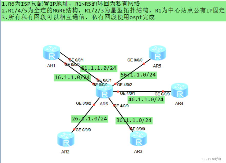
1.R6为ISP只配置IP地址,R1~R5的环回为私有网络
2.R1/4/5为全连的MGRE结构,R1/2/3为星型拓扑结构,R1为中心站点公有IP固定
3.所有私有网段可以相互通信,私有网段使用ospf完成
实验步骤:
1.IP地址规划
使用环回模拟PC:
| 设备 | 环回口IP地址 |
| R1 | 192.168.1.0/24 |
| R2 | 192.168.2.0/24 |
| R3 | 192.168.3.0/24 |
| R4 | 192.168.4.0/24 |
| R5 | 192.168.5.0/24 |
R6环回为6.6.6.6
设备地址:
| 设备 | 接口 | IP地址 |
| R1 | g0/0/0 | 16.1.1.1/24 |
| g0/0/1 | 61.1.1.1/24 | |
| R2 | g0/0/0 | 26.1.1.1/24 |
| R3 | g0/0/0 | 36.1.1.1/24 |
| R4 | g0/0/0 | 46.1.1.1/24 |
| R5 | g0/0/0 | 56.1.1.1/24 |
| R6 | g0/0/0 | 16.1.1.2/24 |
| g0/0/1 | 61.1.1.2/24 | |
| g0/0/2 | 26.1.1.2/24 | |
| g4/0/0 | 36.1.1.2/24 | |
| g4/0/0 | 46.1.1.2/24 | |
| g4/0/2 | 56.1.1.2/24 |
2.配置IP地址
R1上配置:
 [R1]int g0/0/0
 [R1-GigabitEthernet0/0/0]ip add 16.1.1.1 24
 [R1-GigabitEthernet0/0/0]int g0/0/1
 [R1-GigabitEthernet0/0/1]ip add 61.1.1.1 24
 [R1-GigabitEthernet0/0/1]q
 [R1]int l0
 [R1-LoopBack0]ip address 192.168.1.1 24
R2~R6配置与R1相似,具体IP地址见上一步IP地址规划
3.配置缺省路由
[R1]ip route-static 0.0.0.0 0 16.1.1.2
[R1]ip route-static 0.0.0.0 0 61.1.1.2

[R2]ip route-static 0.0.0.0 0 26.1.1.2

[R3]ip route-static 0.0.0.0 0 36.1.1.2

[R4]ip route-static 0.0.0.0 0 46.1.1.2

[R5]ip route-static 0.0.0.0 0 56.1.1.2
4.NAT配置
R1上配置:
[R1]acl 2000
[R1-acl-basic-2000]rule 1 permit source any
[R1-acl-basic-2000]q
[R1]int g0/0/0
[R1-GigabitEthernet0/0/0]nat outbound 2000
[R1-GigabitEthernet0/0/0]int g0/0/1
[R1-GigabitEthernet0/0/1]nat outbound 2000
R2~R5与R1步骤相同
5.R1、R4、R5构建全连MGRE环境
R1配置:
[R1]int Tunnel 0/0/0                            #创建tunnel接口
[R1-Tunnel0/0/0]ip add 10.1.1.1 24              #配接口IP
[R1-Tunnel0/0/0]tunnel-protocol gre p2mp        #修改接口模式为多点GRE(MGRE)
[R1-Tunnel0/0/0]source 61.1.1.1                 #定义公有的源IP地址
[R1-Tunnel0/0/0]nhrp network-id 100             #默认为0号,该网段内所有节点的tunnel接口必须为相同域
[R1-Tunnel0/0/0]nhrp entry multicast dynamic	#本地成为NHRP中心站点,同时可以进行伪广播
[R1-Tunnel0/0/0]nhrp entry 10.1.1.4 46.1.1.1 register
[R1-Tunnel0/0/0]nhrp entry 10.1.1.5 56.1.1.1 register
R4配置:
[R4]int Tunnel 0/0/0
[R4-Tunnel0/0/0]ip add 10.1.1.4 24
[R4-Tunnel0/0/0]tunnel-protocol gre p2mp
[R4-Tunnel0/0/0]source 46.1.1.1
[R4-Tunnel0/0/0]nhrp network-id 100
[R4-Tunnel0/0/0]nhrp entry multicast dynamic
[R4-Tunnel0/0/0]nhrp entry 10.1.1.1 61.1.1.1 register
[R4-Tunnel0/0/0]nhrp entry 10.1.1.5 56.1.1.1 register
R5配置:
[R5]int Tunnel 0/0/0
[R5-Tunnel0/0/0]ip add 10.1.1.5 24
[R5-Tunnel0/0/0]tunnel-protocol gre p2mp
[R5-Tunnel0/0/0]source 56.1.1.1
[R5-Tunnel0/0/0]nhrp network-id 100
[R5-Tunnel0/0/0]nhrp entry multicast dynamic	#本地成为NHRP中心站点,同时可以进行伪广播
[R5-Tunnel0/0/0]nhrp entry 10.1.1.1 61.1.1.1 register
[R5-Tunnel0/0/0]nhrp entry 10.1.1.4 46.1.1.1 register
6.R1、R2、R3构建星型拓扑结构(R1为中心站点)
R1配置:
[R1]int Tunnel 0/0/1                           #创建tunnel接口
[R1-Tunnel0/0/1]ip add 20.1.1.1 24              #配接口IP
[R1-Tunnel0/0/1]tunnel-protocol gre p2mp        #修改接口模式为多点GRE(MGRE)
[R1-Tunnel0/0/1]source 16.1.1.1                 #定义公有的源IP地址
[R1-Tunnel0/0/1]nhrp network-id 101             #默认为0号,该网段内所有节点的tunnel接口必须为相同域
[R1-Tunnel0/0/1]nhrp entry multicast dynamic	#本地成为NHRP中心站点,同时可以进行伪广播
R2配置:
[R2]int Tunnel 0/0/1                            #创建tunnel接口
[R2-Tunnel0/0/1]ip add 20.1.1.2 24              #配接口IP
[R2-Tunnel0/0/1]tunnel-protocol gre p2mp        #修改接口模式为多点GRE(MGRE)
[R2-Tunnel0/0/1]source g0/0/0                   #定义公有的源IP地址
[R2-Tunnel0/0/1]nhrp network-id 101             #默认为0号,该网段内所有节点的tunnel接口必须为相同域
[R2-Tunnel0/0/1] nhrp entry 20.1.1.1 16.1.1.1 register   #分支去到中心站点注册,第一个为中心站点的私有tunnel接口ip地址,第二个为中心站点的公有IP地址
R3配置:
[R3]int Tunnel 0/0/1 #创建tunnel接口
[R3-Tunnel0/0/1]ip add 20.1.1.3 24 #配接口IP
[R3-Tunnel0/0/1]tunnel-protocol gre p2mp #修改接口模式为多点GRE(MGRE)
[R3-Tunnel0/0/1]source g0/0/0 #定义公有的源IP地址
[R3-Tunnel0/0/1]nhrp network-id 101 #默认为0号,该网段内所有节点的tunnel接口必须为相域
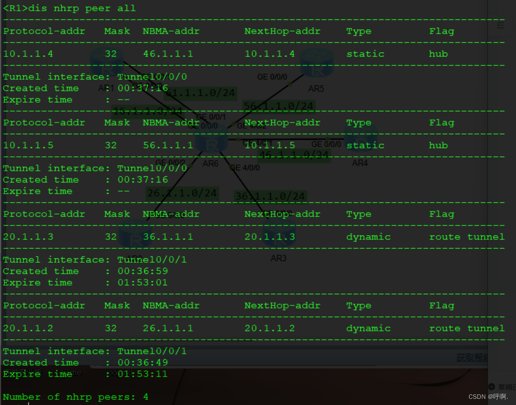
[R3-Tunnel0/0/1]nhrp entry 20.1.1.1 16.1.1.1 register #分支去到中心站点注册,第一个为中心站点的私有tunnel接口ip地址,第二个为中心站点的公有IP地址dis nhrp peer all查看所有NHRP peer表信息。
7.OSPF配置:
R1配置:
[R1]ospf 1 router-id 1.1.1.1
[R1-ospf-1]area 0
[R1-ospf-1-area-0.0.0.0]network 192.168.1.0 0.0.0.255
[R1-ospf-1-area-0.0.0.0]network 10.1.1.0 0.0.0.255
[R1-ospf-1-area-0.0.0.0]network 20.1.1.0 0.0.0.255
R2配置:
[R2]ospf 1 router-id 2.2.2.2
[R2-ospf-1]area 0
[R2-ospf-1-area-0.0.0.0]network 192.168.2.0 0.0.0.255
[R2-ospf-1-area-0.0.0.0]network 20.1.1.0 0.0.0.255
R3配置:
[R3]ospf 1 router-id 3.3.3.3
[R3-ospf-1]area 0
[R3-ospf-1-area-0.0.0.0]network 192.168.3.0 0.0.0.255
[R3-ospf-1-area-0.0.0.0]network 20.1.1.0 0.0.0.255
R4配置:
[R4]ospf 1 router-id 4.4.4.4
[R4-ospf-1]area 0
[R4-ospf-1-area-0.0.0.0]network 192.168.4.0 0.0.0.255
[R4-ospf-1-area-0.0.0.0]network 10.1.1.0 0.0.0.255
R5配置:
[R5]ospf 1 router-id 5.5.5.5
[R5-ospf-1]area 0
[R5-ospf-1-area-0.0.0.0]network 192.168.5.0 0.0.0.255
[R5-ospf-1-area-0.0.0.0]network 10.1.1.0 0.0.0.255
display ospf interface命令用来显示OSPF的接口信息。MGRE属于NBMA网络类型,需要将通道接口的网络类型由默认的P2P变更为broadcast
修改R1~R5通道接口为broadcast口
[R1]int t 0/0/0
[R1-Tunnel0/0/0]ospf network-type broadcast
[R1-Tunnel0/0/0]q
[R1]int t0/0/1
[R1-Tunnel0/0/1]ospf network-type broadcast
[R2]int t0/0/0
[R2-Tunnel0/0/0]ospf network-type broadcast
[R3]int t0/0/0
[R3-Tunnel0/0/0]ospf network-type broadcast
[R4]int t0/0/1
[R4-Tunnel0/0/1]ospf network-type broadcast
[R5]int t0/0/0
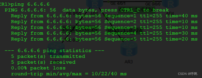
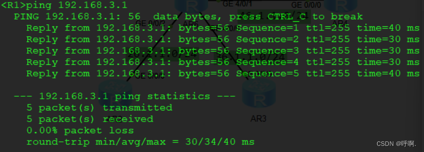
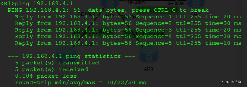
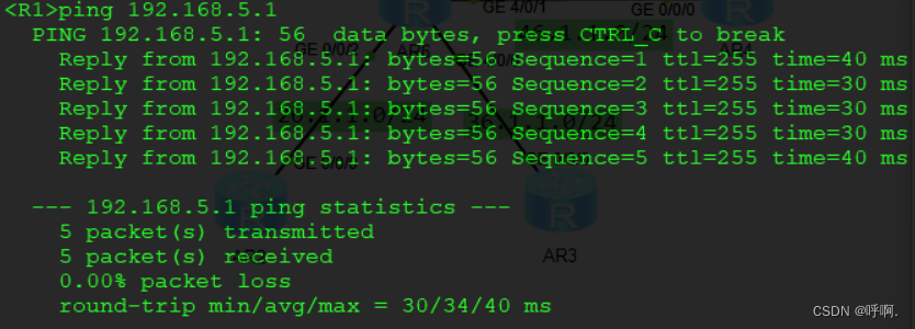
[R5-Tunnel0/0/0]ospf network-type broadcast8.测试

9.配置一览
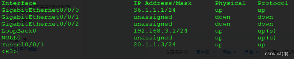
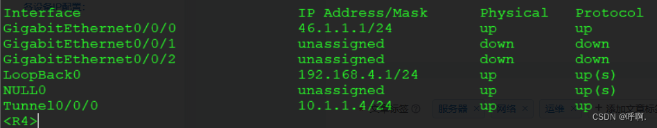
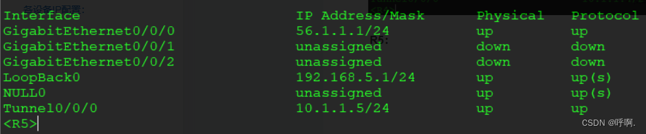
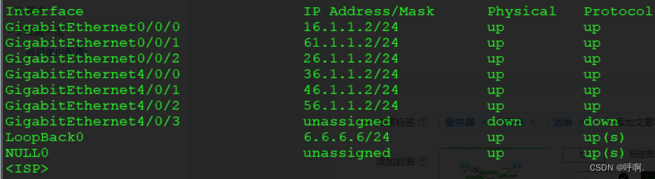
各设备IP配置:
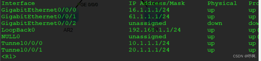
R1:
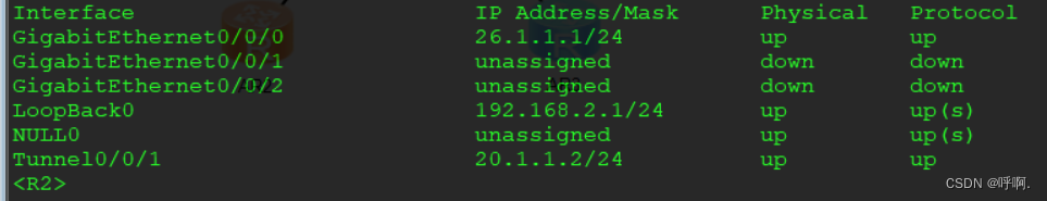
R2:
R3:
R4:
R5:
R6:
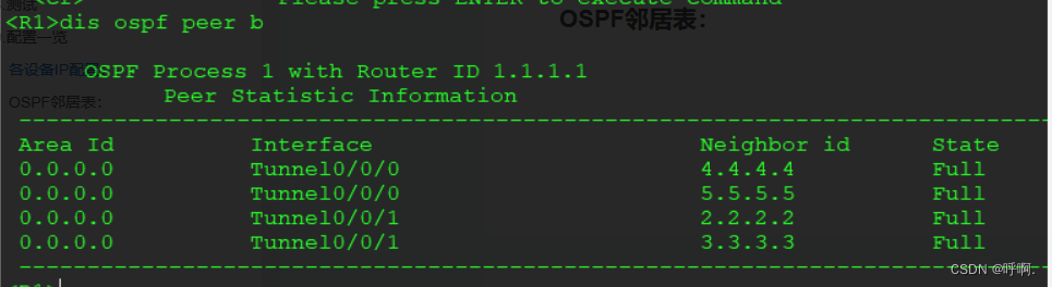
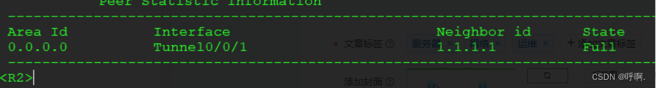
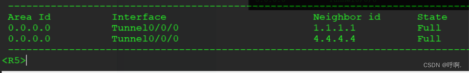
OSPF邻居表:
R1:
R2:
R3: 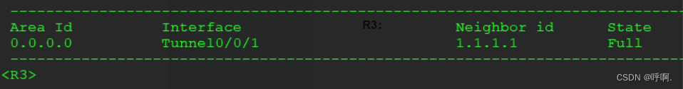
R4:
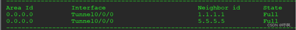
R5:


 被折叠的 条评论
为什么被折叠?
被折叠的 条评论
为什么被折叠?
 到【灌水乐园】发言


