


目录
常见的矩阵键盘是4X4的,如果按照一个按键开关对应一个IO口,那得需要16的IO口,但是STM32单片机IO口总共就那么几个,如果按键使用了这么多,其他的模块就难以使用。
如下是一个4X4的矩阵键盘,但是只需要8个IO口
设计图
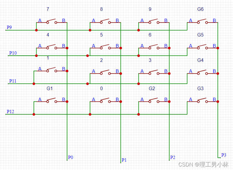
分四行四列,首先,对行判断,看四行中哪个被触发了,再对列判断,看四列中哪个被触发了,行和列对应起来,就是4X4坐标中的某一个位置。
原理:
行判断:首先对四行都设置为上拉输入,四列设置为低电平,当某一个开关按下时,则该行会判别到低电平,从而让我们知道是哪个按键被触发了。
列判断:再改变输入输出模式,让四列为上拉输入,四行为低电平,当某一个开关被按下时,则该列会被判别到低电平,从而让我们知道是哪个按键被触发了。
代码部分:KeyMatrix.c 文件
#include "stm32f10x.h"                  // Device header
#include "Delay.h"                 //延时用 可以晚上查一下  很多的
#include "OLED.h"                  //显示用的 OLED显示屏
#define Pin_Row_1  GPIO_Pin_9
#define Pin_Row_2  GPIO_Pin_10
#define Pin_Row_3  GPIO_Pin_11
#define Pin_Row_4  GPIO_Pin_12
//上面是1~4行,下面是1~4列
#define Pin_Column_1  GPIO_Pin_0
#define Pin_Column_2  GPIO_Pin_1
#define Pin_Column_3  GPIO_Pin_2
#define Pin_Column_4  GPIO_Pin_3
#define Port_GPIO  GPIOA

//原理:默认四个接收口为高电平,另外四个输出口为低电平,
//如果按键接通,接收口就回变成低电平,如果变低电平,则给标志Key改变数值
//测量行或者列的电位后,反转接受和输出,再测量列或者行电位。

void KeyMatrix_Init_1(void)//行判断 的基础设置
{
	RCC_APB2PeriphClockCmd(RCC_APB2Periph_GPIOA,ENABLE);

	GPIO_InitTypeDef GPIO_InitStructure1;
	GPIO_InitStructure1.GPIO_Mode = GPIO_Mode_IPU; //对行全设置为上拉输入
	GPIO_InitStructure1.GPIO_Pin = Pin_Row_1|Pin_Row_2|Pin_Row_3|Pin_Row_4;
	GPIO_InitStructure1.GPIO_Speed = GPIO_Speed_50MHz;
	GPIO_Init(Port_GPIO,&GPIO_InitStructure1);

	GPIO_InitTypeDef GPIO_InitStructure2;
	GPIO_InitStructure2.GPIO_Mode = GPIO_Mode_Out_PP ; //对列全设置为输出模式
	GPIO_InitStructure2.GPIO_Pin =  Pin_Column_1|Pin_Column_2|Pin_Column_3| Pin_Column_4;
	GPIO_InitStructure2.GPIO_Speed = GPIO_Speed_50MHz;
	GPIO_Init(Port_GPIO,&GPIO_InitStructure2);
}
int key1=0;
int KeyMatrix_Get_1(void)//行判断
{
	KeyMatrix_Init_1();
	GPIO_WriteBit(Port_GPIO,Pin_Column_1,Bit_RESET);   //对1~4列都设置为低电平
	GPIO_WriteBit(Port_GPIO,Pin_Column_2,Bit_RESET);
	GPIO_WriteBit(Port_GPIO,Pin_Column_3,Bit_RESET);
	GPIO_WriteBit(Port_GPIO,Pin_Column_4,Bit_RESET);
	//Delay_ms(10);消除抖动
	if(GPIO_ReadInputDataBit(Port_GPIO,Pin_Row_1)==0)  //如果第一行为低电平
	{
		Delay_ms(10); key1=4;                          //则给标志key1改变值
	}
	else if(GPIO_ReadInputDataBit(Port_GPIO,Pin_Row_2)==0) //如果第二行改变值  以下同理
	{
		Delay_ms(10);key1=3;
	}
	else if(GPIO_ReadInputDataBit(Port_GPIO,Pin_Row_3)==0)
	{
		Delay_ms(10);key1=2;
	}
	else if(GPIO_ReadInputDataBit(Port_GPIO,Pin_Row_4)==0)
	{
		Delay_ms(10);key1=1;
	}
	else {key1=0;}  //如果都没被按下,则输出为0
	return key1;
}
void KeyMatrix_Init_2(void)  //列判断 的基础设置
{
	RCC_APB2PeriphClockCmd(RCC_APB2Periph_GPIOA,ENABLE);

	GPIO_InitTypeDef GPIO_InitStructure1;
	GPIO_InitStructure1.GPIO_Mode =  GPIO_Mode_Out_PP; //对四行都设置为输出模式
	GPIO_InitStructure1.GPIO_Pin = Pin_Row_1|Pin_Row_2|Pin_Row_3|Pin_Row_4; //1~4行输出
	GPIO_InitStructure1.GPIO_Speed = GPIO_Speed_50MHz;
	GPIO_Init(Port_GPIO,&GPIO_InitStructure1);

	GPIO_InitTypeDef GPIO_InitStructure2;
	GPIO_InitStructure2.GPIO_Mode = GPIO_Mode_IPU ; //1~4列上拉输入
	GPIO_InitStructure2.GPIO_Pin =  Pin_Column_1|Pin_Column_2|Pin_Column_3| Pin_Column_4;
	GPIO_InitStructure2.GPIO_Speed = GPIO_Speed_50MHz;
	GPIO_Init(Port_GPIO,&GPIO_InitStructure2);
}
int key2=0;
int KeyMatrix_Get_2(void)//列判断
{
	KeyMatrix_Init_2();
	GPIO_WriteBit(Port_GPIO,Pin_Row_1,Bit_RESET);  //对1~4行设置为低电平
	GPIO_WriteBit(Port_GPIO,Pin_Row_2,Bit_RESET);
	GPIO_WriteBit(Port_GPIO,Pin_Row_3,Bit_RESET);
	GPIO_WriteBit(Port_GPIO,Pin_Row_4,Bit_RESET);
	//Delay_ms(10);消除抖动
	if(GPIO_ReadInputDataBit(Port_GPIO,Pin_Column_1)==0) //如果第一列为低电平
	{
		Delay_ms(10);key2=4;
	}
	else if(GPIO_ReadInputDataBit(Port_GPIO,Pin_Column_2)==0)
	{
		Delay_ms(10);key2=3;
	}
	else if(GPIO_ReadInputDataBit(Port_GPIO,Pin_Column_3)==0)
	{
		Delay_ms(10);key2=2;
	}
	else if(GPIO_ReadInputDataBit(Port_GPIO,Pin_Column_4)==0)
	{
		Delay_ms(10);key2=1;
	}
	else {key2=0;}  //如果都没被按下,则输出为0
	return key2;
}
//综合行列电平,获得坐标值,比如(1,2)为键盘上的0数字的地方
int key_lie ,key_hang,key_all,key_flag;
int KeyMatrix_Get_All(void)
{
	key_lie=KeyMatrix_Get_1();  //得知哪行被按下了
	key_hang=KeyMatrix_Get_2(); //得知哪列被按下了
	key_all=key_lie+key_hang*10; //让行的值*10  变成两位数 用坐标会更好理解
	switch(key_all)  //判断坐标位置
	{
		case 11:key_flag=1;break;//功能1
		case 12:key_flag=2;break;//数字0
		case 13:key_flag=3;break;//功能2
		case 14:key_flag=4;break;//功能3

		case 21:key_flag=5;break;//数字1
		case 22:key_flag=6;break;//数字2
		case 23:key_flag=7;break;//数字3
		case 24:key_flag=8;break;//功能4

		case 31:key_flag=9;break;//数字4
		case 32:key_flag=10;break;//数字5
		case 33:key_flag=11;break;//数字6
		case 34:key_flag=12;break;//功能5

		case 41:key_flag=13;break;//数字7
		case 42:key_flag=14;break;//数字8
		case 43:key_flag=15;break;//数字9
		case 44:key_flag=16;break;//功能6

		case 00:key_flag=0;break;
	}
	return key_flag;
}

int key_value;
void KeyMatrix_Use(void)  //功能设置处,可以写这些功能都需要做什么
{
	key_value=KeyMatrix_Get_All(); //获得按键代表的值
	switch(key_value)
	{
		case 1:OLED_ShowString(1,1,"G1");break;
		case 2:OLED_ShowNum(1,1,0,1);break;
		case 3:OLED_ShowString(1,1,"G2");break;
		case 4:OLED_ShowString(1,1,"G3");break;

		case 5:OLED_ShowNum(1,1,1,1);break;
		case 6:OLED_ShowNum(1,1,2,1);break;
		case 7:OLED_ShowNum(1,1,3,1);break;
		case 8:OLED_ShowString(1,1,"G4");break;

		case 9:OLED_ShowNum(1,1,4,1);break;
		case 10:OLED_ShowNum(1,1,6,1);break; //5和6的时候设计板子设计反了
		case 11:OLED_ShowNum(1,1,5,1);break;
		case 12:OLED_ShowString(1,1,"G5");break;

		case 13:OLED_ShowNum(1,1,7,1);break;
		case 14:OLED_ShowNum(1,1,8,1);break;
		case 15:OLED_ShowNum(1,1,9,1);break;
		case 16:OLED_ShowString(1,1,"G6");break;

		case 0:OLED_ShowString(1,1,"  ");break;
	}
}
主函数main.c
#include "stm32f10x.h"                  // Device header
#include "OLED.h"
#include "KeyMatrix.h"
int main(void)
{
	OLED_Init();
	while(1)
	{
		KeyMatrix_Use();             //判断按键来实行不同功能
		OLED_ShowString(4,1,"ON");   //显示程序运行
	}
}


 2931
2931

 被折叠的 条评论
为什么被折叠?
被折叠的 条评论
为什么被折叠?
 到【灌水乐园】发言


