


目录
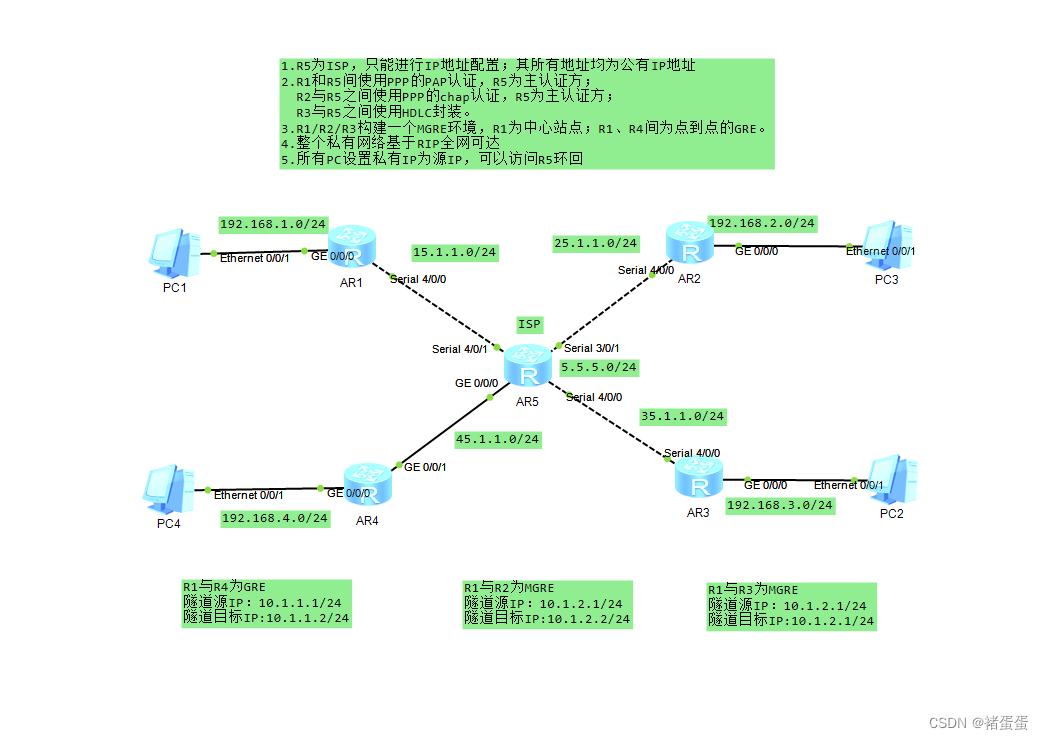
1、R5为ISP,只能进行IP地址配置,其所有地址均配为公有IP地址;
3、R1、R2、R3构建一个MGRE环境,R1为中心站点,R1、R4间为点到点的GRE;
配置完后R2和R3路由条目不全,因为RIP的水平分割(从一个接口收到路由,不从这个接口传出去),所以需要关闭中心接口的水平分割;
一、实验拓扑图
二、实验要求
1、R5为ISP,只能进行IP地址配置,其所有地址均配为公有IP地址;
2、R1和R5间使用PPP的PAP认证,R5为主认证方;
R2与R5之间使用ppp的CHAP认证,R5为主认证方;
R3与R5之间使用HDLC封装;
3、R1、R2、R3构建一个MGRE环境,R1为中心站点,R1、R4间为点到点的GRE;
4、整个私有网络基本RIP全网可达;
5、所有Pc设置私有IP为源IP,可以访问R5环回;
三、实验步骤
1、R5为ISP,只能进行IP地址配置,其所有地址均配为公有IP地址;
先给每个接口配置IP地址
R1:
[r1]interface GigabitEthernet 0/0/0
[r1-GigabitEthernet0/0/0]ip address 192.168.1.1 24
[r1]interface Serial 4/0/0
[r1-Serial4/0/0]ip address 15.1.1.1 24
[r1]display ip interface brief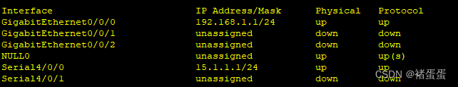
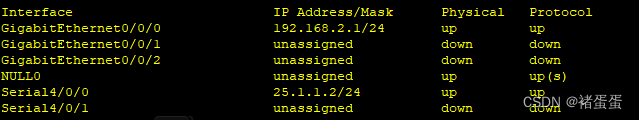
R2:
[r2]interface GigabitEthernet 0/0/0
[r2-GigabitEthernet0/0/0]ip address 192.168.2.1 24
[r2]interface Serial 4/0/0
[r2-Serial4/0/0]ip address 25.1.1.2 24
[r2]display ip interface brief
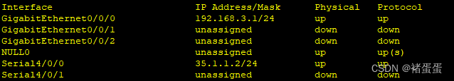
R3:
[r3]interface GigabitEthernet 0/0/0
[r3-GigabitEthernet0/0/0]ip address 192.168.3.1 24
[r3]interface Serial 4/0/0
[r3-Serial4/0/0]ip address 35.1.1.2 24
[r3]display ip interface brief
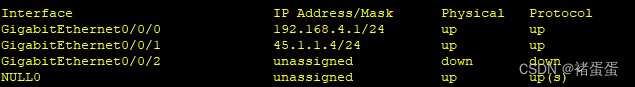
R4:
[r4]interface GigabitEthernet 0/0/1
[r4-GigabitEthernet0/0/1]ip address 45.1.1.4 24
[r4]interface GigabitEthernet 0/0/0
[r4-GigabitEthernet0/0/0]ip address 192.168.4.1 24
[r4]display ip interface brief
R5:
[r5]interface Serial 4/0/1
[r5-Serial4/0/1]ip address 15.1.1.5 24
[r5]interface Serial 3/0/1
[r5-Serial3/0/1]ip address 25.1.1.5 24
[r5]interface Serial 4/0/0
[r5-Serial4/0/0]ip address 35.1.1.5 24
[r5]interface GigabitEthernet 0/0/0
[r5-GigabitEthernet0/0/0]ip address 45.1.1.5 24
[r5]interface LoopBack 0
[r5-LoopBack0]ip address 5.5.5.5 24
[r5]display ip interface brief 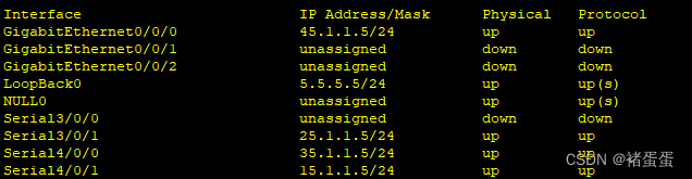
2、R1和R5间使用PPP的PAP认证,R5为主认证方;
R5验证方:配置用户列表及验证方式
[r5]aaa
[r5-aaa]local-user ck password cipher 123 privilege level 15
[r5-aaa]local-user ck service-type ppp
[r5]interface Serial 4/0/1
[r5-Serial4/0/1]ppp authentication-mode pap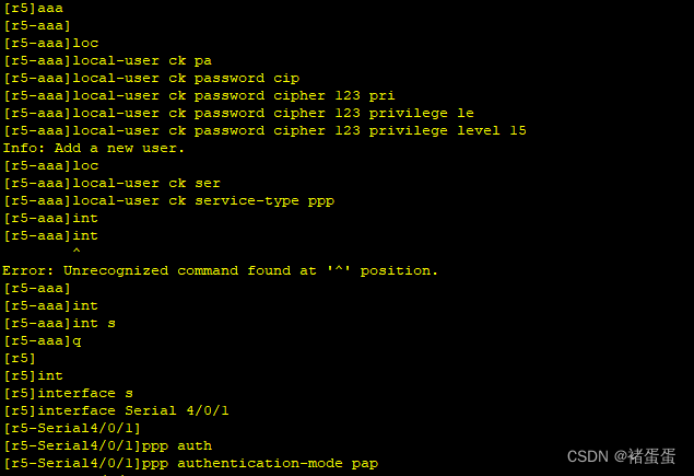
R1被验证方:
[r1]interface Serial 4/0/0
[r1]interface Serial 4/0/0
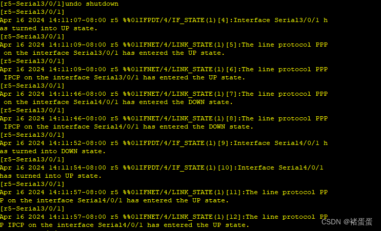
对R1和R5连接的端口都shutdown再开启:
[r1-Serial4/0/0]shutdown
[r1-Serial4/0/0]undo shutdown
[r5-Serial4/0/1]shutdown
[r5-Serial4/0/1]undo shutdown
测试:

R2与R5之间使用ppp的CHAP认证,R5为主认证方;
[r5]aaa
[r5-aaa]local-user cc password cipher 456 privilege level 15
[r5-aaa]local-user cc service-type ppp
[r5]interface Serial 3/0/1
[r5-Serial3/0/1]ppp authentication-mode chap
R2:
[r2]interface Serial 4/0/0
[r2-Serial4/0/0]ppp chap user cc
[r2-Serial4/0/0]ppp chap password cipher 456
对R2和R5连接的端口都shutdown再开启:
[r2-Serial4/0/0]shutdown
[r2-Serial4/0/0]undo shutdown
[r5-Serial3/0/1]shutdown
[r5-Serial3/0/1]undo shutdown 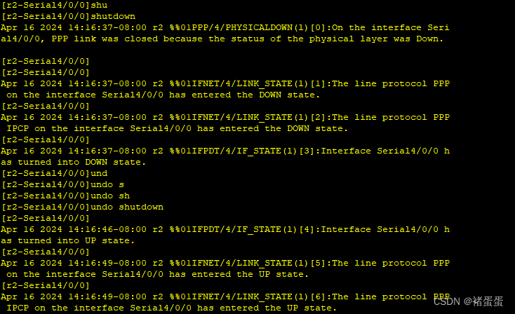
测试:

R3与R5之间使用HDLC封装;
两边接口下修改链路类型:
[r3]interface Serial 4/0/0
[r3-Serial4/0/0]link-protocol hdlc
[r5]interface Serial 4/0/0
[r5-Serial4/0/0]link-protocol hdlc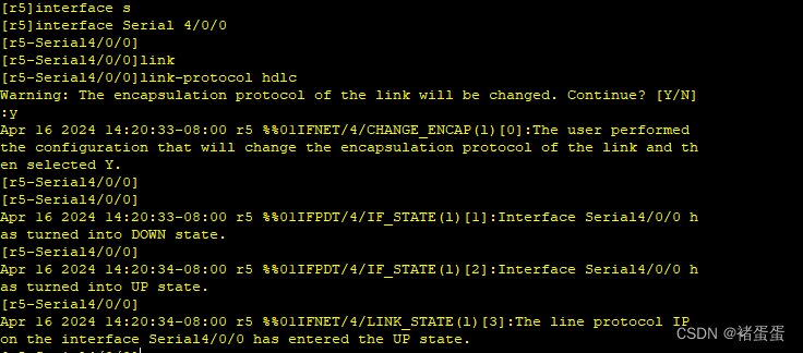
3、R1、R2、R3构建一个MGRE环境,R1为中心站点,R1、R4间为点到点的GRE;
先做R1、R4间为点到点的GRE;
先创建Tunnel接口并且将隧道IP地址加入其中,开启GRE类型以及目标端口IP
R1:
[r1]interface Tunnel 0/0/0
[r1-Tunnel0/0/0]ip address 10.1.1.1 24
[r1-Tunnel0/0/0]tunnel-protocol gre
[r1-Tunnel0/0/0]source 15.1.1.1
[r1-Tunnel0/0/0]destination 45.1.1.4
R4:
[r4]interface Tunnel 0/0/0
[r4-Tunnel0/0/0]ip address 10.1.1.2 24
[r4-Tunnel0/0/0]tunnel-protocol gre
[r4-Tunnel0/0/0]source 45.1.1.4
[r4-Tunnel0/0/0]destination 15.1.1.1
在这里需要配置在R1和R4的出口陪缺省路由才能ping通:
[r1]ip route-static 0.0.0.0 0 15.1.1.5
[r2]ip route-static 0.0.0.0 0 25.1.1.5
[r3]ip route-static 0.0.0.0 0 35.1.1.5
[r4]ip route-static 0.0.0.0 0 45.1.1.5
测试:
[r1]ping -a 15.1.1.1 45.1.1.4
接下来做R1、R2、R3构建一个MGRE环境,R1为中心站点:
1.在做MGRE时首先还是先建立Tunnel隧道
2.给隧道添加IP地址
3.选择MGRE的类型
4.中心接口源IP时固定的写上去就好,但是分支站点不固定需要写他的接口
5.中心接口要开启伪广播,因为分支站点要向中心站点注册
6.设置NHRP的工作IP--下一跳解析协议
中心站点R1:
[r1]interface Tunnel 0/0/1
[r1-Tunnel0/0/1]ip address 10.1.2.1 24(隧道接口IP)
[r1-Tunnel0/0/1]tunnel-protocol gre p2mp(选择mgre环境)
[r1-Tunnel0/0/1]source 15.1.1.1(该隧道加封源IP,地址通过NHRP协议来获取加)
[r1-Tunnel0/0/1]nhrp entry multicast dynamic (本地成为NHRP服务端,开启伪广播,为RIP做准备)
[r1-Tunnel0/0/1]nhrp network-id 100(NHRP的工作编号)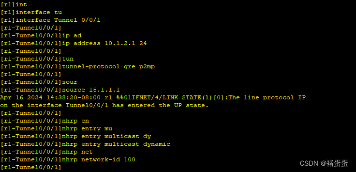
分支站点R2:
[r2]interface Tunnel 0/0/1
[r2-Tunnel0/0/1]ip address 10.1.2.2 24
[r2-Tunnel0/0/1]tunnel-protocol gre p2mp
[r2-Tunnel0/0/1]source Serial 4/0/0
[r2-Tunnel0/0/1]nhrp entry 10.1.2.1 15.1.1.1 register
[r2-Tunnel0/0/1]nhrp network-id 100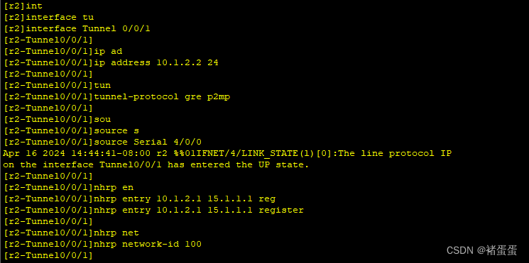
分支站点R3:
[r3]interface Tunnel 0/0/1
[r3-Tunnel0/0/1]ip address 10.1.2.3 24
[r3-Tunnel0/0/1]tunnel-protocol gre p2mp
[r3-Tunnel0/0/1]source Serial 4/0/0
[r3-Tunnel0/0/1]nhrp network-id 100
[r3-Tunnel0/0/1]nhrp entry 10.1.2.1 15.1.1.1 register 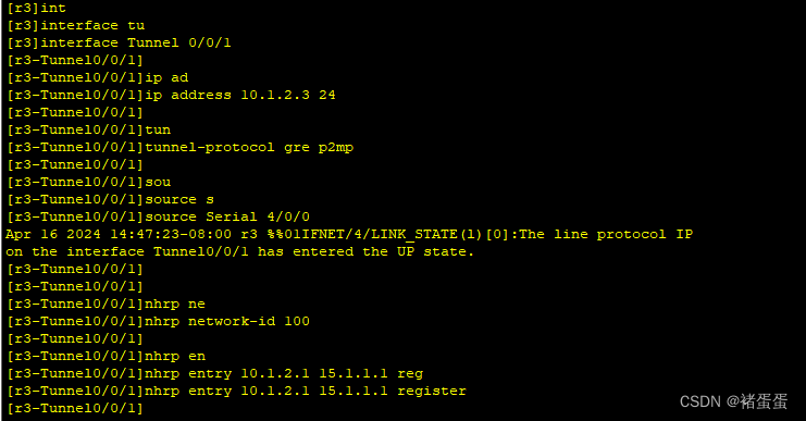
查看和测试:
<r1>display nhrp peer all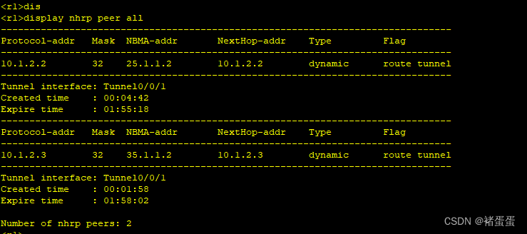
<r1>ping -a 15.1.1.1 35.1.1.2
4、整个私有网络基本RIP全网可达;
因为公网地址私网学不到,所以需要宣告私网
R1:
[r1]rip 1
[r1-rip-1]v 2
[r1-rip-1]undo summary
[r1-rip-1]network 192.168.1.0
[r1-rip-1]network 10.0.0.0
R2:
[r2]rip 1
[r2-rip-1]v 2
[r2-rip-1]undo summary
[r2-rip-1]network 192.168.2.0
[r2-rip-1]network 10.0.0.0

R3:
[r3]rip 1
[r3-rip-1]v 2
[r3-rip-1]undo summary
[r3-rip-1]network 192.168.3.0
[r3-rip-1]network 10.0.0.0
R4:
[r4]rip 1
[r4-rip-1]v 2
[r4-rip-1]undo summary
[r4-rip-1]network 192.168.4.0
[r4-rip-1]network 10.0.0.0

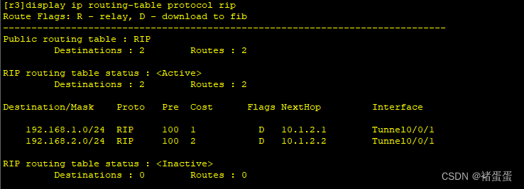
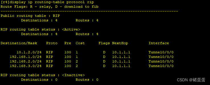
配置完后R2和R3路由条目不全,因为RIP的水平分割(从一个接口收到路由,不从这个接口传出去),所以需要关闭中心接口的水平分割;
R1:
[r1]interface Tunnel 0/0/1
[r1-Tunnel0/0/1]undo rip split-horizon (关闭水平分割机制)

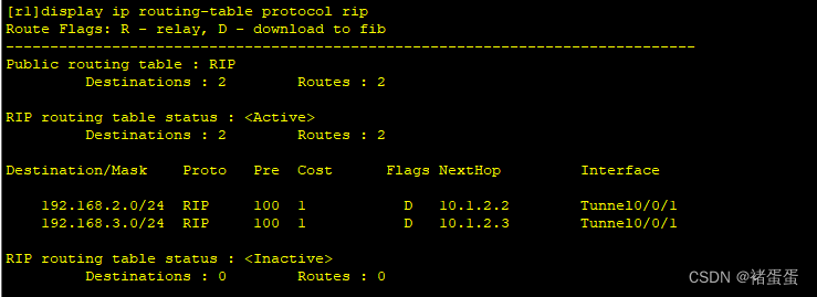
查看:
[r1]display ip routing-table protocol rip
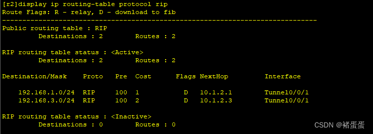
[r2]display ip routing-table protocol rip
[r3]display ip routing-table protocol rip
[r4]display ip routing-table protocol rip
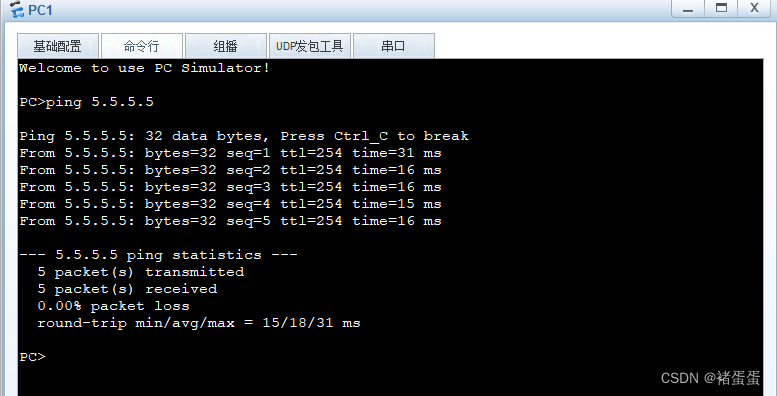
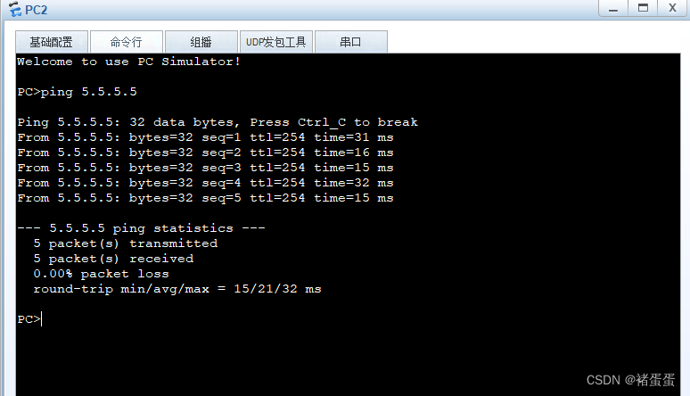
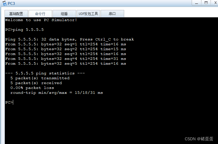
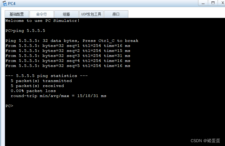
5、所有PC设置私有IP为源IP,可以访问R5环回;
私有IP访问公网环回使用NAT配置:
R1:
[r1]acl 2000
[r1-acl-basic-2000]rule permit source 192.168.1.0 0.0.0.255
[r1]interface Serial 4/0/0
[r1-Serial4/0/0]nat outbound 2000

R2:
[r2]acl 2000
[r2-acl-basic-2000]rule permit source 192.168.2.0 0.0.0.255
[r2]interface Serial 4/0/0
[r2-Serial4/0/0]nat outbound 2000
R3:
[r3]acl 2000
[r3-acl-basic-2000]rule permit source 192.168.3.0 0.0.0.255
[r3]interface Serial 4/0/0
[r3-Serial4/0/0]nat outbound 2000
R4:
[r4]acl 2000
[r4-acl-basic-2000]rule permit source 192.168.4.0 0.0.0.255
[r4]interface GigabitEthernet 0/0/1
[r4-GigabitEthernet0/0/1]nat outbound 2000

四、结果测试


 1474
1474

 被折叠的 条评论
为什么被折叠?
被折叠的 条评论
为什么被折叠?
 到【灌水乐园】发言


