


硬件设计
上篇BLOG中提到我们使用ZC706板子实现USB串口转成JTAG接口所需要的四根信号线,通过PMOD引出。
国产的天嵌通途TQZC706上面使用的使用了一片CP2105来实现USB转串口:
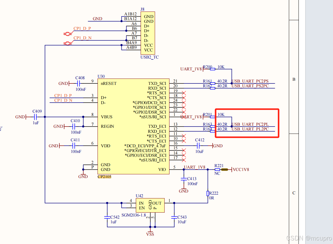
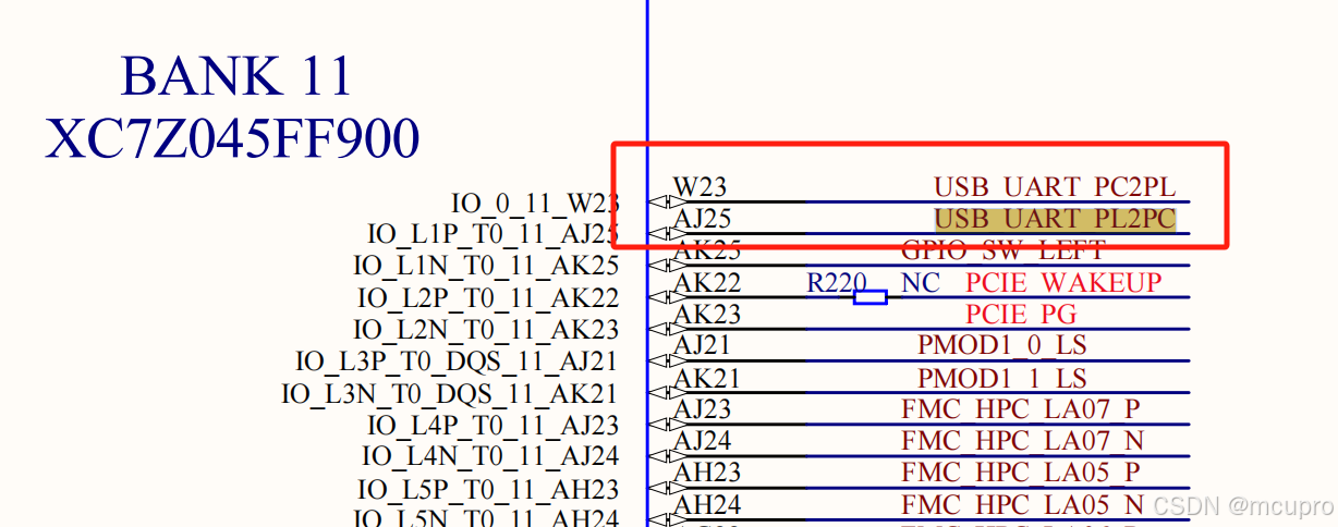
CP2015有能实现USB转成2路串口,在电脑上同时显示两个串口号。TQZC706上将这两个串口分别接给了PS和PL。我们只看PL这个串口,找到了接在W23和AJ25引脚上。
协议设计
我们这里实现了8位双向IO的PORT,典型的需要三个寄存器A,一个可读寄存器实现端口数据的回读,B,一个是控制IO的方向(指示此IO是INPUT还是OUTPUT),C最后一个要输出的内容。
实现A:PC下发一个字节0X03,TQZC706收到了后就返回这个8位IO读到的数
据。
实现B:PC下发字节0X01,之后一个字节是8为IO的方向(1为输出0为输入)。
实现C:PC下发字节0X02,之后一个字节是8位IO的内容(1为输出0为输入)。
逻辑设计
这里用一个UART接口模块,是在【注释1】找到的现成的。使用的时候设置一下波特率和时钟就可以。
代码如下:
// RS-232 RX and TX module
// (c) fpga4fun.com & KNJN LLC - 2003 to 2016
// The RS-232 settings are fixed
// TX: 8-bit data, 2 stop, no-parity
// RX: 8-bit data, 1 stop, no-parity (the receiver can accept more stop bits of course)
//`define SIMULATION // in this mode, TX outputs one bit per clock cycle
// and RX receives one bit per clock cycle (for fast simulations)
module async_transmitter(
input clk,
input TxD_start,
input [7:0] TxD_data,
output TxD,
output TxD_busy
);
// Assert TxD_start for (at least) one clock cycle to start transmission of TxD_data
// TxD_data is latched so that it doesn't have to stay valid while it is being sent
parameter ClkFrequency = 50000000; // 50MHz
//parameter ClkFrequency = 25000000; // 25MHz
parameter Baud = 115200;
generate
if(ClkFrequency<Baud*8 && (ClkFrequency % Baud!=0)) ASSERTION_ERROR PARAMETER_OUT_OF_RANGE("Frequency incompatible with requested Baud rate");
endgenerate
`ifdef SIMULATION
wire BitTick = 1'b1; // output one bit per clock cycle
`else
wire BitTick;
BaudTickGen #(ClkFrequency, Baud) tickgen(.clk(clk), .enable(TxD_busy), .tick(BitTick));
`endif
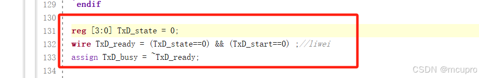
reg [3:0] TxD_state = 0;
wire TxD_ready = (TxD_state==0) && (TxD_start==0) ;//liwei
assign TxD_busy = ~TxD_ready;
reg [7:0] TxD_shift = 0;
always @(posedge clk)
begin
if(TxD_ready & TxD_start)
TxD_shift <= TxD_data;
else
if(TxD_state[3] & BitTick)
TxD_shift <= (TxD_shift >> 1);
case(TxD_state)
4'b0000: if(TxD_start) TxD_state <= 4'b0100;
4'b0100: if(BitTick) TxD_state <= 4'b1000; // start bit
4'b1000: if(BitTick) TxD_state <= 4'b1001; // bit 0
4'b1001: if(BitTick) TxD_state <= 4'b1010; // bit 1
4'b1010: if(BitTick) TxD_state <= 4'b1011; // bit 2
4'b1011: if(BitTick) TxD_state <= 4'b1100; // bit 3
4'b1100: if(BitTick) TxD_state <= 4'b1101; // bit 4
4'b1101: if(BitTick) TxD_state <= 4'b1110; // bit 5
4'b1110: if(BitTick) TxD_state <= 4'b1111; // bit 6
4'b1111: if(BitTick) TxD_state <= 4'b0010; // bit 7
4'b0010: if(BitTick) TxD_state <= 4'b0011; // stop1
4'b0011: if(BitTick) TxD_state <= 4'b0000; // stop2
default: if(BitTick) TxD_state <= 4'b0000;
endcase
end
assign TxD = (TxD_state<4) | (TxD_state[3] & TxD_shift[0]); // put together the start, data and stop bits
endmodule
module async_receiver(
input clk,
input RxD,
output reg RxD_data_ready = 0,
output reg [7:0] RxD_data = 0, // data received, valid only (for one clock cycle) when RxD_data_ready is asserted
// We also detect if a gap occurs in the received stream of characters
// That can be useful if multiple characters are sent in burst
// so that multiple characters can be treated as a "packet"
output RxD_idle, // asserted when no data has been received for a while
output reg RxD_endofpacket = 0 // asserted for one clock cycle when a packet has been detected (i.e. RxD_idle is going high)
);
parameter ClkFrequency = 50000000; // 50MHz
//parameter ClkFrequency = 25000000; // 25MHz
parameter Baud = 115200;
parameter Oversampling = 8; // needs to be a power of 2
// we oversample the RxD line at a fixed rate to capture each RxD data bit at the "right" time
// 8 times oversampling by default, use 16 for higher quality reception
generate
if(ClkFrequency<Baud*Oversampling) ASSERTION_ERROR PARAMETER_OUT_OF_RANGE("Frequency too low for current Baud rate and oversampling");
if(Oversampling<8 || ((Oversampling & (Oversampling-1))!=0)) ASSERTION_ERROR PARAMETER_OUT_OF_RANGE("Invalid oversampling value");
endgenerate
reg [3:0] RxD_state = 0;
`ifdef SIMULATION
wire RxD_bit = RxD;
wire sampleNow = 1'b1; // receive one bit per clock cycle
`else
wire OversamplingTick;
BaudTickGen #(ClkFrequency, Baud, Oversampling) tickgen(.clk(clk), .enable(1'b1), .tick(OversamplingTick));
// synchronize RxD to our clk domain
reg [1:0] RxD_sync = 2'b11;
always @(posedge clk) if(OversamplingTick) RxD_sync <= {RxD_sync[0], RxD};
// and filter it
reg [1:0] Filter_cnt = 2'b11;
reg RxD_bit = 1'b1;
always @(posedge clk)
if(OversamplingTick)
begin
if(RxD_sync[1]==1'b1 && Filter_cnt!=2'b11) Filter_cnt <= Filter_cnt + 1'd1;
else
if(RxD_sync[1]==1'b0 && Filter_cnt!=2'b00) Filter_cnt <= Filter_cnt - 1'd1;
if(Filter_cnt==2'b11) RxD_bit <= 1'b1;
else
if(Filter_cnt==2'b00) RxD_bit <= 1'b0;
end
// and decide when is the good time to sample the RxD line
function integer log2(input integer v); begin log2=0; while(v>>log2) log2=log2+1; end endfunction
localparam l2o = log2(Oversampling);
reg [l2o-2:0] OversamplingCnt = 0;
always @(posedge clk) if(OversamplingTick) OversamplingCnt <= (RxD_state==0) ? 1'd0 : OversamplingCnt + 1'd1;
wire sampleNow = OversamplingTick && (OversamplingCnt==Oversampling/2-1);
`endif
// now we can accumulate the RxD bits in a shift-register
always @(posedge clk)
case(RxD_state)
4'b0000: if(~RxD_bit) RxD_state <= `ifdef SIMULATION 4'b1000 `else 4'b0001 `endif; // start bit found?
4'b0001: if(sampleNow) RxD_state <= 4'b1000; // sync start bit to sampleNow
4'b1000: if(sampleNow) RxD_state <= 4'b1001; // bit 0
4'b1001: if(sampleNow) RxD_state <= 4'b1010; // bit 1
4'b1010: if(sampleNow) RxD_state <= 4'b1011; // bit 2
4'b1011: if(sampleNow) RxD_state <= 4'b1100; // bit 3
4'b1100: if(sampleNow) RxD_state <= 4'b1101; // bit 4
4'b1101: if(sampleNow) RxD_state <= 4'b1110; // bit 5
4'b1110: if(sampleNow) RxD_state <= 4'b1111; // bit 6
4'b1111: if(sampleNow) RxD_state <= 4'b0010; // bit 7
4'b0010: if(sampleNow) RxD_state <= 4'b0000; // stop bit
default: RxD_state <= 4'b0000;
endcase
always @(posedge clk)
if(sampleNow && RxD_state[3]) RxD_data <= {RxD_bit, RxD_data[7:1]};
//reg RxD_data_error = 0;
always @(posedge clk)
begin
RxD_data_ready <= (sampleNow && RxD_state==4'b0010 && RxD_bit); // make sure a stop bit is received
//RxD_data_error <= (sampleNow && RxD_state==4'b0010 && ~RxD_bit); // error if a stop bit is not received
end
`ifdef SIMULATION
assign RxD_idle = 0;
`else
reg [l2o+1:0] GapCnt = 0;
always @(posedge clk) if (RxD_state!=0) GapCnt<=0; else if(OversamplingTick & ~GapCnt[log2(Oversampling)+1]) GapCnt <= GapCnt + 1'h1;
assign RxD_idle = GapCnt[l2o+1];
always @(posedge clk) RxD_endofpacket <= OversamplingTick & ~GapCnt[l2o+1] & &GapCnt[l2o:0];
`endif
endmodule
// dummy module used to be able to raise an assertion in Verilog
module ASSERTION_ERROR();
endmodule
module BaudTickGen(
input clk, enable,
output tick // generate a tick at the specified baud rate * oversampling
);
parameter ClkFrequency = 25000000;
parameter Baud = 115200;
parameter Oversampling = 1;
function integer log2(input integer v); begin log2=0; while(v>>log2) log2=log2+1; end endfunction
localparam AccWidth = log2(ClkFrequency/Baud)+8; // +/- 2% max timing error over a byte
reg [AccWidth:0] Acc = 0;
localparam ShiftLimiter = log2(Baud*Oversampling >> (31-AccWidth)); // this makes sure Inc calculation doesn't overflow
localparam Inc = ((Baud*Oversampling << (AccWidth-ShiftLimiter))+(ClkFrequency>>(ShiftLimiter+1)))/(ClkFrequency>>ShiftLimiter);
always @(posedge clk) if(enable) Acc <= Acc[AccWidth-1:0] + Inc[AccWidth:0]; else Acc <= Inc[AccWidth:0];
assign tick = Acc[AccWidth];
endmodule
这里注意代码我做了一点修改,这样TXD_BUSY信号可以早一周期到达,在状态机进行判断时候可以少一个等待周期,也就是减少一个状态非常方便。
之后我们写代码来实现上述的UART转8通道的IO的协议:使用状态机实现,代码如下:
module uart(
input clk,
input pl_rx,
output pl_tx,
inout io0,io1,io2,io3,io4,io5,io6,io7
);

reg [7:0]   io_out,io_enn,io_inr;
wire [7:0] io_inw ;

assign io0 = (io_enn[0] == 1 ) ? io_out[0] : 'bz ;
assign io1 = (io_enn[1] == 1 ) ? io_out[1] : 'bz ;
assign io2 = (io_enn[2] == 1 ) ? io_out[2] : 'bz ;
assign io3 = (io_enn[3] == 1 ) ? io_out[3] : 'bz ;
assign io4 = (io_enn[4] == 1 ) ? io_out[4] : 'bz ;
assign io5 = (io_enn[5] == 1 ) ? io_out[5] : 'bz ;
assign io6 = (io_enn[6] == 1 ) ? io_out[6] : 'bz ;
assign io7 = (io_enn[7] == 1 ) ? io_out[7] : 'bz ;


assign  io_inw =  { io7,io6,io5,io4,io3,io2,io1,io0 };

always @(posedge clk)  io_inr <= io_inw ;

wire [7:0] RxD_data;
wire RxD_data_ready;

reg [7:0] TxD_data;
reg TxD_start;
wire TxD_busy ;
 async_transmitter async_transmitter(
	.clk(clk),
	.TxD_start(TxD_start),
	.TxD_data(TxD_data),
	.TxD(pl_tx),
	.TxD_busy(TxD_busy)
);

 async_receiver async_receiver(
	.clk(clk),
	.RxD(pl_rx),
	.RxD_data_ready(RxD_data_ready),
	.RxD_data(RxD_data)
);

reg [15:0]  st ;
always @ (posedge clk )case (st)
0:st<=10;
10:if(RxD_data_ready) st<=15;
15:case(RxD_data)
1:st<=100; //set outdata
2:st<=200; //set oen
3:st<=300; //read back
default st<=400;//loop back
endcase

100:if(RxD_data_ready) st<=105;//io_out = RxD_data
105:st<=10;

200:if(RxD_data_ready) st<=205;//io_enn = RxD_data
205:st<=10;

300:if(~TxD_busy) st<=305;
305:st<=10;

400:if(~TxD_busy)st<=405;
405:st<=10;

default:st<=0;
endcase

always@(posedge clk)if(st==100 && RxD_data_ready == 1) io_out <= RxD_data;
always@(posedge clk)if(st==200 && RxD_data_ready == 1) io_enn <= RxD_data;
always@(posedge clk)case (st)
300:  if (~TxD_busy) TxD_data <=   io_inr   ;
400:  if (~TxD_busy) TxD_data <=   RxD_data ;
endcase

always@(posedge clk)if((st==300 ||  st==400) && TxD_busy == 0  )TxD_start<=1; else TxD_start<=0;

endmodule
这里用到了输入输出的三态IO模块,这个模块只存在于FPGA的物理接口出,因此我们在GENERATE OUTPUT PRODUCTS时候要选择GLOBAL全局模式,如下图:

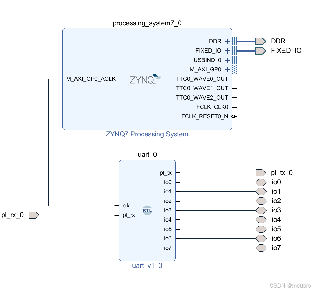
为了实现SD卡或者FLASH启动我们还需要配置一下ZYNQ,顺便输出一个时钟给PL用。BLOCK DESIGN如下图:
 为了生成启动文件BOOT.BIN除了生成的BIT流文件之外,还需要生成FSBL和一个简单用户程序HELLO WORD。我们按部就班生成就好。
上位机程序设计
上位机实现串口的读写,以及上述按照实现转换8位IO。代码如下:
#include "stdio.h"

static   FILE*fp ;
int init_log_file(char*fn  )
{
    fp=fopen(fn,"wb");

    if(fp==NULL)return-1 ;
    return 1 ;
}

int release_log_file()
{
    fclose(fp);
    return 1 ;
}

int add_to_log_file(char*str)
{
    fprintf(fp,"%s\n",str);
    return 1 ;
}


// RS-232 example
// Compiles with Microsoft Visual C++ 5.0/6.0
// verion 42390034371
// (c) fpga4fun.com KNJN LLC - 2003, 2004, 2005, 2006

#include <windows.h>
#include <stdio.h>
#include <conio.h>
#include <time.h>


HANDLE hCom;

void OpenCom(unsigned int port ,unsigned int baud )
{
	static   char b[10];
	DCB dcb;
	COMMTIMEOUTS ct;
	if (port >= 10 ) sprintf(b,"\\\\.\\COM%d",port);else 	sprintf(b,"COM%d",port);
	hCom = CreateFile(b, GENERIC_READ | GENERIC_WRITE, 0, NULL, OPEN_EXISTING, FILE_ATTRIBUTE_NORMAL, NULL);
	if(hCom==INVALID_HANDLE_VALUE) exit(1);
	if(!SetupComm(hCom, 4096, 4096)) exit(1);
	if(!GetCommState(hCom, &dcb)) exit(1);
	dcb.BaudRate = baud ;
	((unsigned int *)(&dcb))[2] = 0x1001;  // set port properties for TXDI + no flow-control
	dcb.ByteSize = 8;
	dcb.Parity = NOPARITY;
	dcb.StopBits = 2;
	if(!SetCommState(hCom, &dcb)) exit(1);	// set the timeouts to 0
	ct.ReadIntervalTimeout = MAXDWORD ;
	ct.ReadTotalTimeoutMultiplier = 0;
	ct.ReadTotalTimeoutConstant = 0;
	ct.WriteTotalTimeoutMultiplier = 0;
	ct.WriteTotalTimeoutConstant = 0;
	if(!SetCommTimeouts(hCom, &ct)) exit(1);
	printf("ok to open %s with %d \n",b,baud  );
}

void CloseCom()
{
	CloseHandle(hCom);
}

unsigned int  WriteCom(unsigned char* buf, int len)
{
	unsigned int  nSend ;

	if(!WriteFile(hCom, buf, len, &nSend, NULL)) exit(1);
	return nSend;
}

void WriteComChar(unsigned char b)
{
	WriteCom(&b, 1);
}

unsigned char  ReadCom(unsigned char *buf, int len)
{
	unsigned char  nRec;
	if(!ReadFile(hCom, buf, len, &nRec, NULL)) exit(1);
	return (unsigned char )nRec;
}

unsigned char ReadComChar()
{
	unsigned int  nRec;	char c;
	do {
			if(!ReadFile(hCom, &c, 1, &nRec, NULL)) exit(1);

	}
	while (nRec==0    ) ;
	return   c  ;
}

unsigned char ReadComCharTimeOut(int * msec)
{
	int de ;
	int start = clock();
	int end =start + *msec ;*msec=0;
	unsigned int  nRec;	char c;
	do {
			if(!ReadFile(hCom, &c, 1, &nRec, NULL)) exit(1);
		    if (end <= clock()){ *msec = -1 ; break;}
	}
	while (nRec==0    ) ;
	return   c  ;
}


unsigned int  ReadComU32()
{
	unsigned int r,t ;
	unsigned char a[4];
	a[0] =  ReadComChar();
	a[1] =  ReadComChar();
	a[2] =  ReadComChar();
	a[3] =  ReadComChar();
	t=a[3];r=t;r<<=8;
	t=a[2];r|=t;r<<=8;
	t=a[1];r|=t;r<<=8;
	t=a[0];r|=t;
	return r ;
}//chcked


unsigned int  ReadComU32TimeOut(int * msec)
{
	static int ms  ;
    int ms_save = *msec ;
	*msec =0;
	unsigned int r,t ;
	unsigned char a[4];

ms = ms_save; a[0] =	ReadComCharTimeOut(&ms); if (ms==-1){  *msec=-1;return 0; }
ms = ms_save; a[1] =	ReadComCharTimeOut(&ms); if (ms==-1){  *msec=-1;return 0; }
ms = ms_save; a[2] =	ReadComCharTimeOut(&ms); if (ms==-1){  *msec=-1;return 0; }
ms = ms_save; a[3] =	ReadComCharTimeOut(&ms); if (ms==-1){  *msec=-1;return 0; }

	t=a[3];r=t;r<<=8;
	t=a[2];r|=t;r<<=8;
	t=a[1];r|=t;r<<=8;
	t=a[0];r|=t;

	return r ;

}


void WriteComU32(unsigned int  b)
{

	unsigned int r,t ;
	static unsigned char a[4];
t=b;
a[0]=t & 0xff;t >>=8;
a[1]=t & 0xff;t >>=8;
a[2]=t & 0xff;t >>=8;
a[3]=t & 0xff;

	WriteCom(a, 4);
} //check


unsigned char get_port (unsigned char mask ){

	unsigned char r  ;
	WriteComChar(0x03);
	r = ReadComChar();
	r &= mask  ;
	return (r==0)?0:1;
}


unsigned char set_dir (unsigned char p ){
	WriteComChar(0x02);
	WriteComChar(p);
}

unsigned char set_port (unsigned char p ){
	WriteComChar(0x01);
	WriteComChar(p);
}

unsigned char echo_test(){

	unsigned int i;
	unsigned char   r  ;
	for(i=4;i<100;++i)  {
	WriteComChar(i);
	r = ReadComChar();
		if ( r != i ) printf("echo test failed !\n");
		if ( r != i ) exit(1);
	}
	printf("tested ok!\n");
}
这里我们看到代码实现了0x03指令get_port,0X01指令set_dir,以及0x02号指令set_port。另外害实现了一个echo_test测试使用正确连接TQZC706实现解析。
至此我们已经实现了在上位机使用C控制ZC706的PMOD的8位IO的通道。接下来我们将在此平台上实现JATG的TAP状态机转换实现。这就主要是上位机软件方面的工作了。


 被折叠的 条评论
为什么被折叠?
被折叠的 条评论
为什么被折叠?
 到【灌水乐园】发言


