


1.下载工具
有window和Linux版本(可以支持ubuntu20.04),用官网释放的工具就行,有些电脑要关掉安全启动usb驱动才能工作正常,也可以使用开源的usb驱动(https://github.com/linux-sunxi/sunxi-livesuite)。
2.下载方式
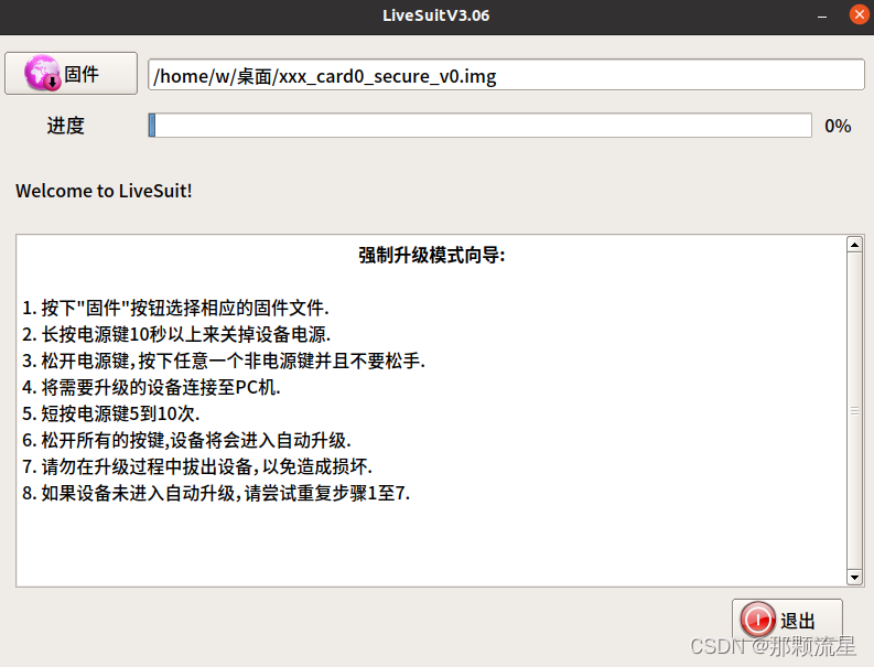
如下载工具的提示,注意需要接电池哦。
就是关机状态下,先按住任意按键(非电源键),然后接usb,按几下电源键,然后松开所以按键。
还有就是强制下载方式,先接电池,烧录键(FEL)引脚然后对地,然后接usb。
3.编译
3.1 cd longan, ./build.sh(编译uboot,kernel等)
3.2 cd 源码根目录,Android标准编译方法
3.3 打包(pack)打包支持卡打印,不需要焊接串口线,有时比较方便
4.lcd调试
disp init configuration

disp_mode             (0:screen0<screen0,fb0>)
screenx_output_type   (0:none; 1:lcd; 2:tv; 3:hdmi;5:vdpo)
screenx_output_mode   (used for hdmi output, 0:480i 1:576i 2:480p 3:576p 4:720p50)
                      (5:720p60 6:1080i50 7:1080i60 8:1080p24 9:1080p50 10:1080p60)
screenx_output_format (for hdmi, 0:RGB 1:yuv444 2:yuv422 3:yuv420)
screenx_output_bits   (for hdmi, 0:8bit 1:10bit 2:12bit 2:16bit)
screenx_output_eotf   (for hdmi, 0:reserve 4:SDR 16:HDR10 18:HLG)
screenx_output_cs     (for hdmi, 0:undefined  257:BT709 260:BT601  263:BT2020)
screenx_output_dvi_hdmi (for hdmi, 0:undefined 1:dvi mode 2:hdmi mode)
screen0_output_range   (for hdmi, 0:default 1:full 2:limited)
screen0_output_scan    (for hdmi, 0:no data 1:overscan 2:underscan)
screen0_output_aspect_ratio  (for hdmi, 8-same as original picture 9-4:3 10-16:9 11-14:9)
fbx format            (4:RGB655 5:RGB565 6:RGB556 7:ARGB1555 8:RGBA5551 9:RGB888 10:ARGB8888 12:ARGB4444)
fbx pixel sequence    (0:ARGB 1:BGRA 2:ABGR 3:RGBA)
fb0_scaler_mode_enable(scaler mode enable, used FE)
fbx_width,fbx_height  (framebuffer horizontal/vertical pixels, fix to output resolution while equal 0)
lcdx_backlight        (lcd init backlight,the range:[0,256],default:197
lcdx_yy               (lcd init screen bright/contrast/saturation/hue, value:0~100, default:50/50/57/50)
lcd0_contrast         (LCD contrast, 0~100)
lcd0_saturation       (LCD saturation, 0~100)
lcd0_hue              (LCD hue, 0~100)
framebuffer software rotation setting:
disp_rotation_used:   (0:disable; 1:enable,you must set fbX_width to lcd_y,
set fbX_height to lcd_x)
degreeX:              (X:screen index; 0:0 degree; 1:90 degree; 3:270 degree)
degreeX_Y:            (X:screen index; Y:layer index 0~15; 0:0 degree; 1:90 degree; 3:270 degree)
devX_output_type : config output type in bootGUI framework in UBOOT-2018.
                                   (0:none; 1:lcd; 2:tv; 4:hdmi;)
devX_output_mode : config output resolution(see include/video/sunxi_display2.h) of bootGUI framework in UBOOT-2018
devX_screen_id   : config display index of bootGUI framework in UBOOT-2018
devX_do_hpd      : whether do hpd detectation or not in UBOOT-2018
chn_cfg_mode     : Hardware DE channel allocation config. 0:single display with 6
                                   channel, 1:dual display with 4 channel in main display and 2 channel in second
                   display, 2:dual display with 3 channel in main display and 3 channel in second
                   in display.
&disp {
...
fb0_width = <1200>;
fb0_height = <1920>;4
...
};
;lcd0 configuration

;lcd_if:               0:hv(sync+de); 1:8080; 2:ttl; 3:lvds; 4:dsi; 5:edp; 6:extend dsi
;lcd_hv_if             0:Parallel RGB; 8:Serial RGB; 10:Dummy RGB; 11: RGB Dummy;12:CCIR656
;lcd_hv_clk_phase      0:0 degree;1:90 degree;2:180 degree;3:270 degree
;lcd_hv_sync_polarity  0:vs low,hs low; 1:vs high,hslow; 2:vs low,hs high; 3:vs high,hs high
;lcd_hv_syuv_seq       0:YUYV; 1:YVYU; 2:UYVY; 3:VYUY
;lcd_cpu_if            0:18bit/1 cycle parallel(RGB666); 4:16bit/1cycle parallel (RGB565)
;                      6:18bit/3 cycle parallel(RGB666); 7:16bit/2cycle parallel (RGB565)
;lcd_cpu_te            0:frame auto trigger; 1:frame triggered by te rising edge; 2:frame triggered by te falling edge;
;lcd_dsi_if            0:video mode; 1: Command mode; 2:video burst mode
;lcd_dsi_te            0:frame auto trigger; 1:frame triggered by te rising edge; 2:frame triggered by te falling edge;
;lcd_x:                lcd horizontal resolution
;lcd_y:                lcd vertical resolution
;lcd_width:            width of lcd in mm
;lcd_height:           height of lcd in mm
;lcd_dclk_freq:        in MHZ unit
;lcd_pwm_freq:         in HZ unit
;lcd_pwm_pol:          lcd backlight PWM polarity
;lcd_pwm_max_limit     lcd backlight PWM max limit(<=255)
;lcd_hbp:              hsync back porch(pixel) + hsync plus width(pixel);
;lcd_ht:               hsync total cycle(pixel)
;lcd_vbp:              vsync back porch(line) + vysnc plus width(line)
;lcd_vt:               vysnc total cycle(line)
;lcd_hspw:             hsync plus width(pixel)
;lcd_vspw:             vysnc plus width(pixel)
;lcd_lvds_if:          0:single link;  1:dual link
;lcd_lvds_colordepth:  0:8bit; 1:6bit
;lcd_lvds_mode:        0:NS mode; 1:JEIDA mode
;lcd_frm:              0:disable; 1:enable rgb666 dither; 2:enable rgb656 dither
;lcd_io_phase:         0:noraml; 1:intert phase(0~3bit: vsync phase; 4~7bit:hsync phase;
;                      8~11bit:dclk phase; 12~15bit:de phase)
;lcd_gamma_en          lcd gamma correction enable
;lcd_bright_curve_en   lcd bright curve correction enable
;lcd_cmap_en           lcd color map function enable
;deu_mode              0:smoll lcd screen; 1:large lcd screen(larger than 10inch)
;lcdgamma4iep:         Smart Backlight parameter, lcd gamma vale * 10;
;                      decrease it while lcd is not bright enough; increase while lcd is too bright
;smart_color           90:normal lcd screen 65:retina lcd screen(9.7inch)
;Pin setting for special function ie.LVDS, RGB data or vsync
;   name(donot care) = port:PD12<pin function><pull up or pull down><drive ability><output level>
;Pin setting for gpio:
;   lcd_gpio_X     = port:PD12<pin function><pull up or pull down><drive ability><output level>
;Pin setting for backlight enable pin
;   lcd_bl_en     = port:PD12<pin function><pull up or pull down><drive ability><output level>
;fsync setting, pulse to csi
;lcd_fsync_en          (0:disable fsync,1:enable)
;lcd_fsync_act_time    (active time of fsync, unit:pixel)
;lcd_fsync_dis_time    (disactive time of fsync, unit:pixel)
;lcd_fsync_pol         (0:positive;1:negative)
;gpio config: <&pio for cpu or &r_pio for cpus, port, port num, pio function,
pull up or pull down(default 0), driver level(default 1), data>
;For dual link lvds: use lvds2link_pins_a  and lvds2link_pins_b instead
;For rgb24: use rgb24_pins_a  and rgb24_pins_b instead
;For lvds1: use lvds1_pins_a  and lvds1_pins_b instead
;For lvds0: use lvds0_pins_a  and lvds0_pins_b instead
&lcd0 {
lcd_used = <1>;
status = "okay";
lcd_driver_name = "hx8279d_mipi_panel";
lcd_backlight = <50>;
lcd_if = <4>;
lcd_x = <1200>;
lcd_y = <1920>;
lcd_width = <135>;
lcd_height = <216>;
lcd_dclk_freq = <154>;
lcd_hbp = <38>;
lcd_ht = <1296>;
lcd_hspw = <20>;
lcd_vbp = <20>;
lcd_vt = <1980>;
lcd_vspw = <20>;
lcd_pin_power = "dcdc1";
lcd_power1 = "dcdc1";
lcd_power2 = "dc1sw";
lcd_gpio_0 = <&pio PD 22 1 0 3 1>;
lcd_gpio_1 = <&pio PD 23 1 0 3 1>;
};需要兼容多款屏幕,lcd0_1,lcd0_2,...,uboot通过sunxi_lcd_switch_compat_panel切换屏幕,如
sunxi_lcd_switch_compat_panel(sel, 1);/*switch to lcd0_1*/
sunxi_lcd_switch_compat_panel(sel, 2);/*switch to lcd0_2*/
注意下屏参,设计不够人性化,有时需要重新计算
lcd_dclk_freq=lcd_ht*lcd_vt*fps
lcd_hbp: hsync back porch(pixel) + hsync plus width(pixel);
lcd_ht: hsync total cycle(pixel)
lcd_vbp: vsync back porch(line) + vysnc plus width(line)
lcd_vt: vysnc total cycle(line)
lcd_hspw: hsync plus width(pixel)
lcd_vspw: vysnc plus width(pixel)
刷机第一次启动后,回记忆当前的屏幕,第二次启动直接初始化刷机后读到的屏幕,这样能加快启动速度,但如果换屏了,屏幕就不亮了,可以去掉该机制。
竖屏横显这块适配的比较好,配置相应的宏就行。
5.外置音频PA配置
dts有如下节点gpio-spk就是pa使能的节点
&codec {
...
        pa_level        = <0x01>;
        pa_msleep_time  = <0x78>;
        gpio-spk        = <&pio PH 6 GPIO_ACTIVE_HIGH>;
...

};
如果pa通过写寄存器使能,需要替换使能接口,如
longan/kernel/linux-5.4/sound/soc/sunxi/sun50iw10-codec.c(里控制gpio的函数替换成其他函数)
6.wifi和bt配置
官方有相应的适配文档,如Android_11_Wi-Fi_BT_开发指南.pdf
如device/softwinner/ceres/xxx/BoardConfig.mk
BOARD_WIFI_VENDOR := aic
BOARD_USR_WIFI    := aic8800
WIFI_DRIVER_MODULE_PATH := "/vendor/lib/modules/aic8800_fdrv.ko"
WIFI_DRIVER_MODULE_NAME := aic8800_fdrv
WIFI_DRIVER_MODULE_ARG  :=

# 2. Bluetooth Configuration
BOARD_BLUETOOTH_VENDOR    := aic
BOARD_HAVE_BLUETOOTH_NAME := aic8800
BOARD_BLUETOOTH_CONFIG_DIR :=  $(PRODUCT_PLATFORM_PATH)/common/wireless/bluetooth
# Must include after wifi/bt configuration
include device/softwinner/common/config/wireless/wireless_config.mk
关注下 include device/softwinner/common/config/wireless/wireless_config.mk
  else ifeq ($(BOARD_WIFI_VENDOR),aic)
        BOARD_WLAN_DEVICE           := aic
        BOARD_WPA_SUPPLICANT_PRIVATE_LIB := lib_driver_cmd_aic
        BOARD_HOSTAPD_PRIVATE_LIB   := lib_driver_cmd_aic
        BOARD_WIRELESS_PROPERTIES   += wifi.direct.interface=p2p-dev-wlan0
        -include hardware/aic/wlan/firmware/$(BOARD_USR_WIFI)/device-aic.mk
    else ifeq ($(BOARD_BLUETOOTH_VENDOR),aic)
        BOARD_HAVE_BLUETOOTH_AIC := true
        BOARD_CUSTOM_BT_CONFIG      := $(BOARD_CUSTOM_BT_CONFIG_TMP)
        -include hardware/aic/libbt/firmware/$(BOARD_HAVE_BLUETOOTH_NAME)/aic-bt.mk
BoardConfig.mk的修改就是为了编译hardware相应的文件
关注下这个定义
WIFI_DRIVER_MODULE_PATH := "/vendor/lib/modules/aic8800_fdrv.ko"
WIFI_DRIVER_MODULE_NAME := aic8800_fdrv
#ifdef WIFI_DRIVER_MODULE_PATH
static const char DRIVER_MODULE_NAME[] = WIFI_DRIVER_MODULE_NAME;
static const char DRIVER_MODULE_TAG[] = WIFI_DRIVER_MODULE_NAME " ";
static const char DRIVER_MODULE_PATH[] = WIFI_DRIVER_MODULE_PATH;
static const char DRIVER_MODULE_ARG[] = WIFI_DRIVER_MODULE_ARG;
static const char MODULE_FILE[] = "/proc/modules";
#endif

int wifi_load_driver() {

...
  if (insmod(DRIVER_MODULE_PATH, DRIVER_MODULE_ARG) < 0) return -1;
...
}

int wifi_unload_driver() {
...
#ifdef WIFI_DRIVER_MODULE_PATH
  if (rmmod(DRIVER_MODULE_NAME) == 0) {
...
}
打开/关闭 wifi回加载定义的wifi驱动。
wifi不工作时,可检查wifi模块电源,时钟,wifi模块驱动能否正常加载等。
7.sensor配置
7.1 sensor兼容
device/softwinner/ceres/xxx/input/sensor_modules.cfg
如
handle=ID_A
+path= mir3da.ko
+path= mc34xx.ko
7.2 sensor配置方向
device/softwinner/ceres/xxx/input/gsensor.cfg
8.调整串口打印等级
device/softwinner/ceres/ceres-xx/system/env.cfg
-loglevel=4
+loglevel=8


 1784
1784

 被折叠的 条评论
为什么被折叠?
被折叠的 条评论
为什么被折叠?
 到【灌水乐园】发言


