


GPIO除了输入输出,一般还有很丰富的复用功能,以ESP32为例:

我们在上次开关量输出(HIGH/LOW)先来看输入信号一般的用法:
1. 读取外部接口状态--开关信号量,比如按键
2. 模拟输入, 读取外部信号的电压值
3. 用作中断触发,当状态改变时触发中断,进入预设的处理程序
GPIO其他的输出功能:
1. DAC/PWM
然后就是组合的高速串口接口了,SPI/I2C最为典型,和通用串口的差异就在于支持高速的数据传输,而且主要以同步传输为主(带时钟信号)。
我们这一节主要来看输入的应用,主要三个案例:
1. 读取状态;
2. 增加去抖动处理,提高可靠性
3. 通过模拟输入实现一个IO处理多个按键
4.*触发外部中断
案例1,读取光电开关状态,并控制LED
初级,直接控制状态
/*
  GPIO digital input.
  P12 connected to an optical switch.

*/
#define LED_ON LOW
#define LED_OFF HIGH

#define SWITCH_ON HIGH
#define SWITCH_OFF LOW

// These constants won't change. They're used to give names to the pins used:
const int switchInput=12;
const int led=22;


int switchState ;        // value read from the pot


void setup() {
  // initialize serial communications at 9600 bps:

  pinMode(switchInput,INPUT);
  pinMode(led,OUTPUT);
}

void loop() {
  // read the analog in value:
  switchState=digitalRead(switchInput);
  if(switchState==SWITCH_ON) digitalWrite(led,LED_ON);

  else digitalWrite(led,LED_OFF);


  delay(2);
}
案例2 .升级,加入去抖
/*
  GPIO digital input.
  P12 connected to an optical switch.

*/
#define LED_ON LOW
#define LED_OFF HIGH


#define SWITCH_ON HIGH
#define SWITCH_OFF LOW

// These constants won't change. They're used to give names to the pins used:
const int switchInput=12;
const int led=22;


int switchState = SWITCH_OFF;        // value read from the pot

int lastState=SWITCH_OFF;
int ledState=LED_OFF;

unsigned long lastDebounceTime = 0;  // the last time the output pin was toggled
unsigned long debounceDelay = 50;    // the debounce time; increase if the output flickers


void setup() {
  // initialize serial communications at 9600 bps:
  Serial.begin(9600);
  pinMode(switchInput,INPUT);
  pinMode(led,OUTPUT);
  digitalWrite(led,ledState);
}

void loop() {
  // read the analog in value:
  int readValue=digitalRead(switchInput);
  if(readValue!=lastState){
    // reset the debounce timer
    lastDebounceTime=millis();
    }
   if((millis()-lastDebounceTime)>debounceDelay){
    // longer than limit,set the actual state
    if(readValue!=switchState){

      switchState=readValue;

      if(switchState==SWITCH_ON){
        ledState=!ledState;
        Serial.println("led stat changed.");
      }
    }
  }
  digitalWrite(led,ledState);
  // save the read value.
   lastState=readValue;
}
关键Arduino库函数: millis(), digitalRead()
digitalRead() - Arduino Reference
案例3, 一个GPIO通过读取模拟信号量来获取多个控制按键
电路连接的原理
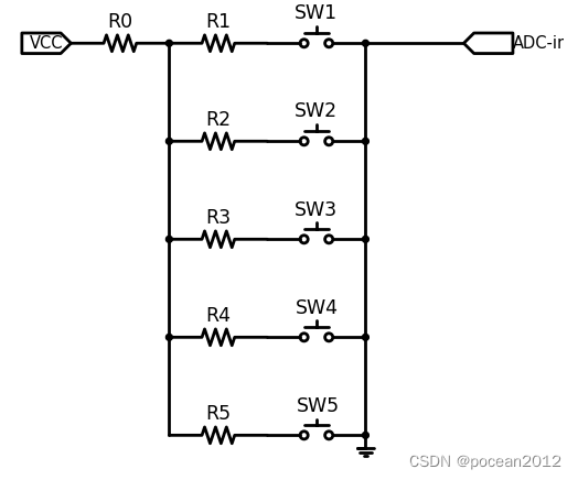
代码
// These constants won't change. They're used to give names to the pins used:
const int analogInPin = 12;  // Analog input pin that the potentiometer is attached to
const int led = 22; // Analog output pin that the LED is attached to

int sensorValue = 0;        // value read from the pot


void setup() {
  // initialize serial communications at 9600 bps:
  Serial.begin(9600);
}

void loop() {
  // read the analog in value:
  sensorValue = analogRead(analogInPin);

  // print the results to the Serial Monitor:
  Serial.print("sensor = ");
  Serial.print(sensorValue);
  Serial.print("\n ");


  // wait 2 milliseconds before the next loop for the analog-to-digital
  // converter to settle after the last reading:
  delay(2);
}
时间关系, 留给大家思考的题目:
1. 怎么分辨多按键?
2. 怎么进行滤波处理?
3. 能否处理组合键?
4. 如何处理按下和释放?
Micropython的示例代码:
import machine
from machine import ADC,Pin
import time

led=machine.Pin(22,machine.Pin.OUT)

adc=ADC(Pin(33))

while True:

    adcValue=adc.read()

    print("voltage: %d mv \r\n"%(adcValue))
    time.sleep(0.1)


 2030
2030

 被折叠的 条评论
为什么被折叠?
被折叠的 条评论
为什么被折叠?
 到【灌水乐园】发言


