


摘要
本章节主要讲述如何使用cubemx、HAL库点亮LED灯,希望教程对正在学习HAL库的你有用哦~系列教程主要在STM32F407ZGT6探索者开发板完成,部分在自设计fallingstar board完成。
cubemx配置
不知道怎么新建工程的童鞋,麻烦移步新建工程章节,新建工程:见新建工程详解
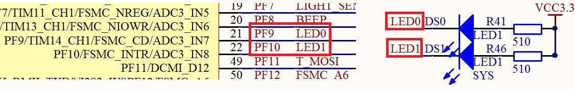
硬件连接,可以看到,F407探索者的LED灯是连接在PF9、PF10引脚上的,采用的是灌电流的设计方式,亮灯只需要控制相应IO就可以了:
-
高电平:熄灭
-
低电平:亮
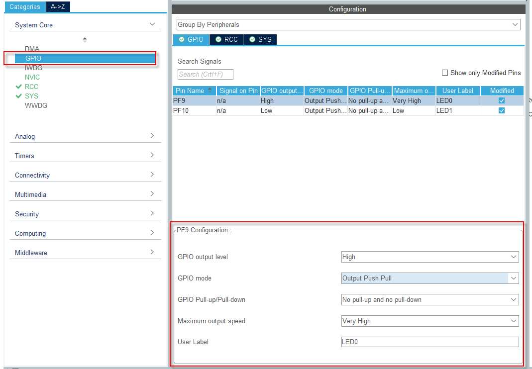
 选择需要配置的引脚,PF9,和PF10,仅以PF9配置为例说明
 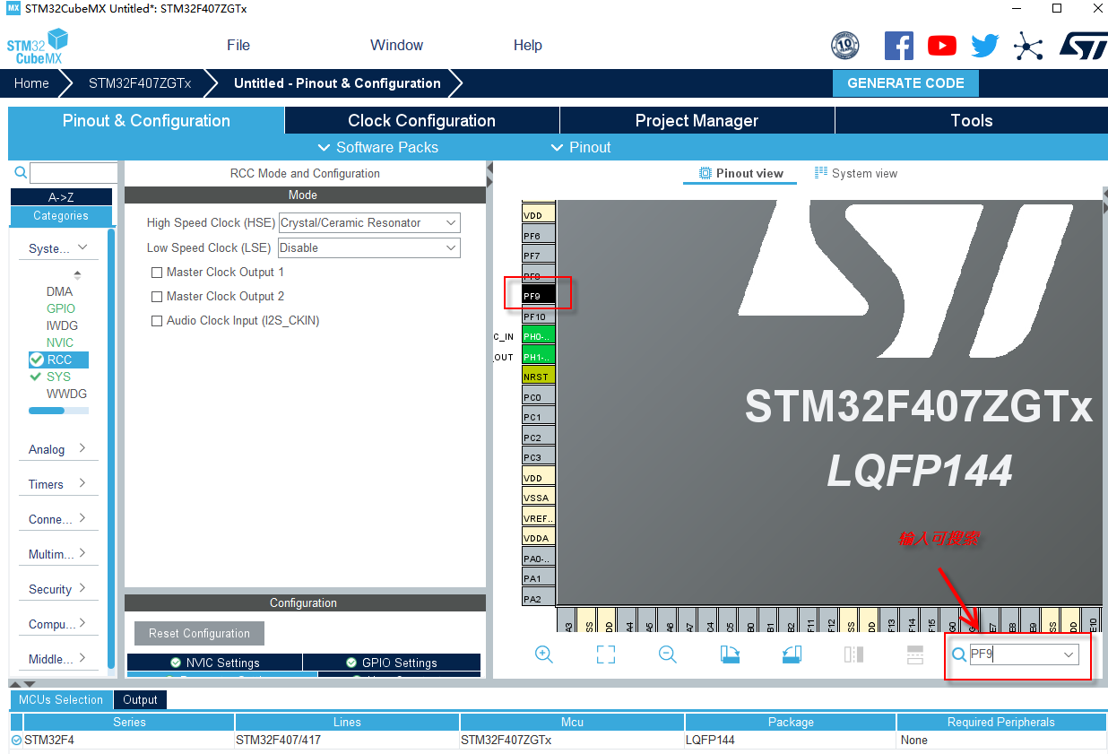 配置为输出模式
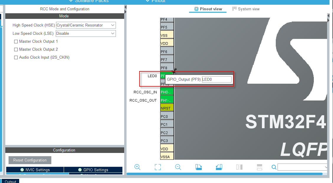
 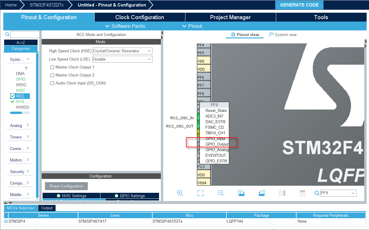 右击可以编辑label,定义为我们自己的label,建议养成好的习惯,顾名思义,也会很方便移植
 MCU的IO是可以根据需要配置为不同的模式的,关于IO输出模式下,主要有这几项配置
-
GPIO output level 初始化IO输出电平状态,High-高电平,Low-低电平
-
GPIO mode GPIO的输出模式配置,Output Push Pull-推挽输出,Output Open Drain-开漏输出
-
GPIO PULL—UP/PULL-DOWN PULL—UP:上拉,PULL-DOWN:下拉,NO pull-up and no pull
-
Maximum output speed IO最大输出速度
-
User Label 自定义用户标签
在HAL库中定义如下:
typedef struct
{
  uint32_t Pin;       /*!< Specifies the GPIO pins to be configured.
                           This parameter can be any value of @ref GPIO_pins_define */

  uint32_t Mode;      /*!< Specifies the operating mode for the selected pins.
                           This parameter can be a value of @ref GPIO_mode_define */

  uint32_t Pull;      /*!< Specifies the Pull-up or Pull-Down activation for the selected pins.
                           This parameter can be a value of @ref GPIO_pull_define */

  uint32_t Speed;     /*!< Specifies the speed for the selected pins.
                           This parameter can be a value of @ref GPIO_speed_define */

  uint32_t Alternate;  /*!< Peripheral to be connected to the selected pins.
                            This parameter can be a value of @ref GPIO_Alternate_function_selection */
}GPIO_InitTypeDef;
时钟树图 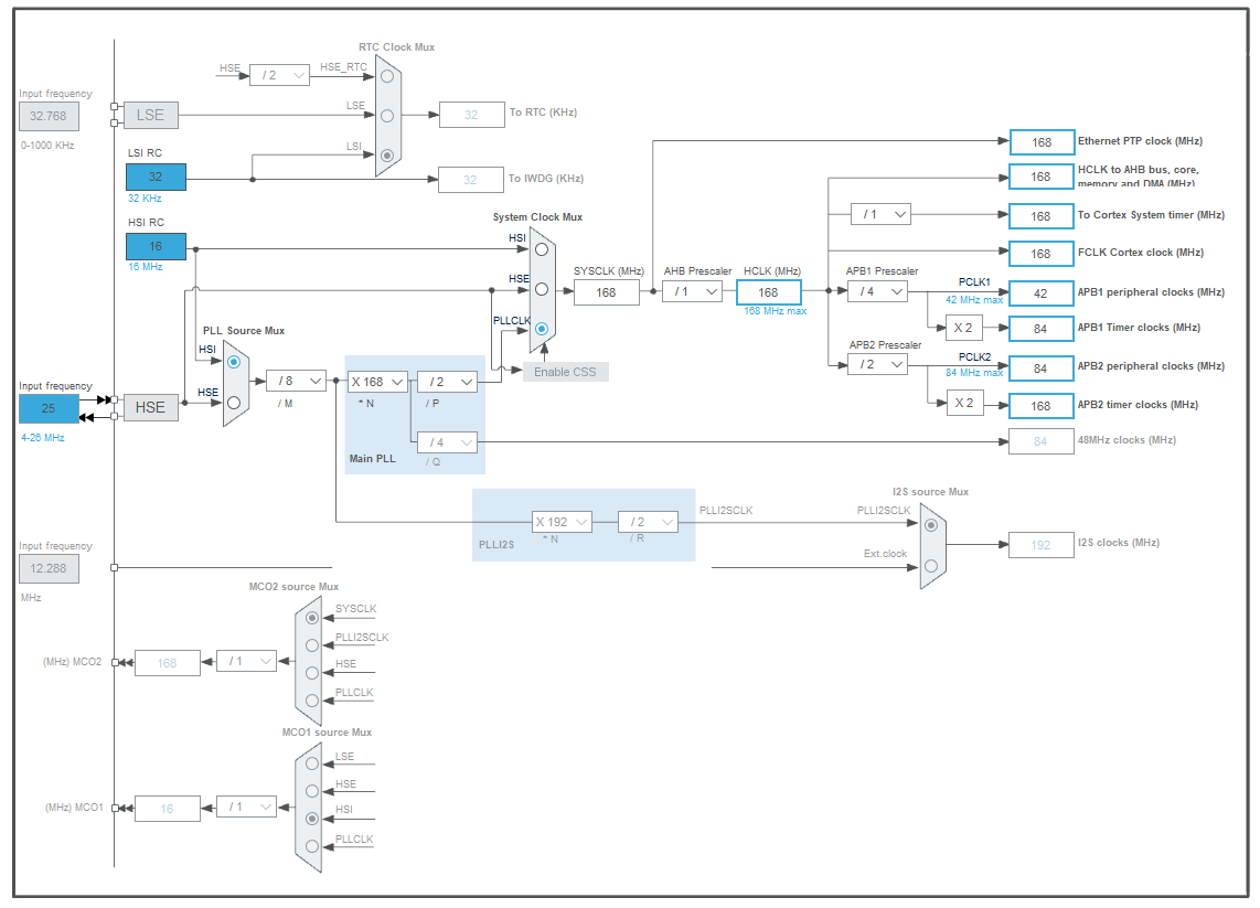
配置完成,然后生成代码就可以了
源码解析
生成的关于LED GPIO的代码
void MX_GPIO_Init(void)
{

  GPIO_InitTypeDef GPIO_InitStruct = {0};

  /* GPIO Ports Clock Enable */
  __HAL_RCC_GPIOF_CLK_ENABLE();
  __HAL_RCC_GPIOH_CLK_ENABLE();
  __HAL_RCC_GPIOA_CLK_ENABLE();
  __HAL_RCC_GPIOB_CLK_ENABLE();

  /*Configure GPIO pin Output Level */
  HAL_GPIO_WritePin(GPIOF, LED0_Pin|LED1_Pin, GPIO_PIN_SET);

  /*Configure GPIO pins : PFPin PFPin */
  GPIO_InitStruct.Pin = LED0_Pin|LED1_Pin;
  GPIO_InitStruct.Mode = GPIO_MODE_OUTPUT_PP;
  GPIO_InitStruct.Pull = GPIO_PULLUP;
  GPIO_InitStruct.Speed = GPIO_SPEED_FREQ_VERY_HIGH;
  HAL_GPIO_Init(GPIOF, &GPIO_InitStruct);

}
接下来看看HAL库关于GPIO控制的一些函数,根据说明,填入参数即可,第一个参数,GPIOA...G...,根据GPIO所在的分组,填入,第二个参数,GPIO具体的位置,第三个参数,GPIO的电平控制,0/1,所以说,平时写代码,在网上冲浪查找是一种办法,看源代码也是一种好办法,结构体、枚举,都会有体现,一边实战一边学习
typedef enum
{
  GPIO_PIN_RESET = 0,
  GPIO_PIN_SET
}GPIO_PinState;
/**
  * @brief  Sets or clears the selected data port bit.
  *
  * @note   This function uses GPIOx_BSRR register to allow atomic read/modify
  *         accesses. In this way, there is no risk of an IRQ occurring between
  *         the read and the modify access.
  *
  * @param  GPIOx where x can be (A..K) to select the GPIO peripheral for STM32F429X device or
  *                      x can be (A..I) to select the GPIO peripheral for STM32F40XX and STM32F427X devices.
  * @param  GPIO_Pin specifies the port bit to be written.
  *          This parameter can be one of GPIO_PIN_x where x can be (0..15).
  * @param  PinState specifies the value to be written to the selected bit.
  *          This parameter can be one of the GPIO_PinState enum values:
  *            @arg GPIO_PIN_RESET: to clear the port pin
  *            @arg GPIO_PIN_SET: to set the port pin
  * @retval None
  */
void HAL_GPIO_WritePin(GPIO_TypeDef* GPIOx, uint16_t GPIO_Pin, GPIO_PinState PinState)
{
  /* Check the parameters */
  assert_param(IS_GPIO_PIN(GPIO_Pin));
  assert_param(IS_GPIO_PIN_ACTION(PinState));

  if(PinState != GPIO_PIN_RESET)
  {
    GPIOx->BSRR = GPIO_Pin;
  }
  else
  {
    GPIOx->BSRR = (uint32_t)GPIO_Pin << 16U;
  }
}
除了上面的函数可以设置IO状态,还有下面这个,这个函数,每次执行会自动把状态翻转,参数比上面少一个。
/**
  * @brief  Toggles the specified GPIO pins.
  * @param  GPIOx Where x can be (A..K) to select the GPIO peripheral for STM32F429X device or
  *                      x can be (A..I) to select the GPIO peripheral for STM32F40XX and STM32F427X devices.
  * @param  GPIO_Pin Specifies the pins to be toggled.
  * @retval None
  */
void HAL_GPIO_TogglePin(GPIO_TypeDef* GPIOx, uint16_t GPIO_Pin)
{
  uint32_t odr;

  /* Check the parameters */
  assert_param(IS_GPIO_PIN(GPIO_Pin));

  /* get current Ouput Data Register value */
  odr = GPIOx->ODR;

  /* Set selected pins that were at low level, and reset ones that were high */
  GPIOx->BSRR = ((odr & GPIO_Pin) << GPIO_NUMBER) | (~odr & GPIO_Pin);
}
下面来演示两种不同的用法:
  while (1)
  {
    /* USER CODE END WHILE */

    /* USER CODE BEGIN 3 */
  HAL_GPIO_TogglePin(LED0_GPIO_Port,LED0_Pin);
  HAL_GPIO_TogglePin(LED1_GPIO_Port,LED1_Pin);
  HAL_Delay(500);

  }
  while (1)
  {
    /* USER CODE END WHILE */

    /* USER CODE BEGIN 3 */

    HAL_GPIO_WritePin(LED0_GPIO_Port, LED0_Pin, GPIO_PIN_RESET);
    HAL_GPIO_WritePin(LED0_GPIO_Port, LED0_Pin, GPIO_PIN_RESET);

    HAL_Delay(500);
    HAL_GPIO_WritePin(LED0_GPIO_Port, LED0_Pin, GPIO_PIN_RESET);
    HAL_GPIO_WritePin(LED0_GPIO_Port, LED0_Pin, GPIO_PIN_RESET);

    HAL_Delay(500);
  }
两种实现的效果是一样的哦~ OK,完美,end~
资料获取
可以添加小飞哥好友,进群交流获取资料,也可以公众号后台回复“HAL_GPIO”获取源码! 


 1万+
1万+


 被折叠的 条评论
为什么被折叠?
被折叠的 条评论
为什么被折叠?
 到【灌水乐园】发言


