


Framebuffer设备
Framebuffer 翻译过来就是帧缓冲,简称 fb,因 此大家在以后的 Linux 学习中见到“Framebuffer”或者“fb”的话第一反应应该想到 RGBLCD 或者显示设备。fb 是一种机制,将系统中所有跟显示有关的硬件以及软件集合起来,虚拟出一 个 fb 设备,当我们编写好 LCD 驱动以后会生成一个名为/dev/fbX(X=0~n)的设备,应用程序通 过访问/dev/fbX 这个设备就可以访问 LCD0
![[外链图片转存失败,源站可能有防盗链机制,建议将图片保存下来直接上传(img-s65PNdGp-1665926095085)(C:\Users\WIN10\AppData\Roaming\Typora\typora-user-images\1665230625415.png)]](https://img-blog.csdnimg.cn/e1cf11ef4a7049d9bb4a2c47e4f5e539.png)
帧缓冲设备为标准的字符型设备,在Linux中主设备号29,定义在/include/linux/major.h中的FB_MAJOR,次设备号定义帧缓冲的个数,最大允许有32个FrameBuffer,定义在/include/linux/fb.h中的FB_MAX,对应于文件系统下/dev/fb%d设备文件
驱动编写步骤:
1.修改设备设备树,依据屏幕信息修改设备树(重点)
2.编写驱动有个文件,fbmem.c(不需要我们编写),xxxfb.c(如果没有提供就需要我们编写)
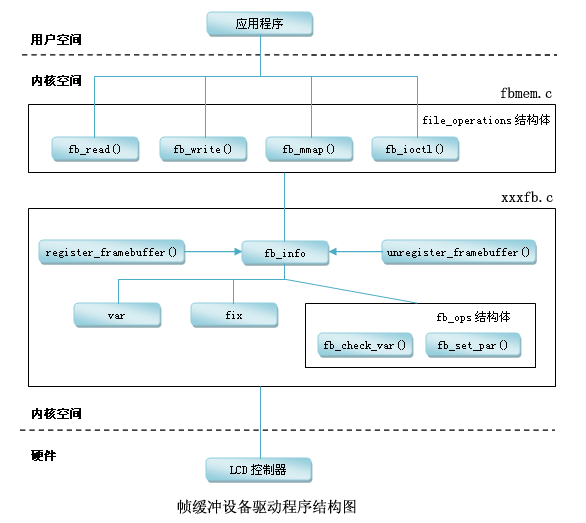
我们从上面这幅图看,帧缓冲设备在Linux中也可以看做是一个完整的子系统,大体由fbmem.c和xxxfb.c组成。
fbmem.c
linux-4.19.35\linux-4.19.35\drivers\video\fbdev\core\fbmem.c
向上给应用程序提供完善的设备文件操作接口(即对FrameBuffer设备进行read、write、ioctl等操作),接口在Linux提供的fbmem.c文件中实现;
在这个文件里面实现文件操作集的函数接口实现,找到对应的info结构体
xxxfb.c
linux-4.19.35\linux-4.19.35\drivers\video\fbdev\mxsfb.c
向下提供了硬件操作的接口,只是这些接口Linux并没有提供实现,因为这要根据具体的LCD控制器硬件进行设置,所以这就是我们要做的事情了(即xxxfb.c部分的实现)。
分析fbmem.c文件和xxfb.c文件的关系
fbmem.c文件
![[外链图片转存失败,源站可能有防盗链机制,建议将图片保存下来直接上传(img-grYuRqff-1665926095088)(C:\Users\WIN10\AppData\Roaming\Typora\typora-user-images\1665885446503.png)]](https://img-blog.csdnimg.cn/b602f746f6f5443e97b16579cbfcf69f.png)
![[外链图片转存失败,源站可能有防盗链机制,建议将图片保存下来直接上传(img-Q4Y2lPhC-1665926095088)(C:\Users\WIN10\AppData\Roaming\Typora\typora-user-images\1665885467118.png)]](https://img-blog.csdnimg.cn/6eaa345a7c8f41db8497b2c9b8daef81.png)
![[外链图片转存失败,源站可能有防盗链机制,建议将图片保存下来直接上传(img-5HwvkRLZ-1665926095089)(C:\Users\WIN10\AppData\Roaming\Typora\typora-user-images\1665885509471.png)]](https://img-blog.csdnimg.cn/f867a3b5093341118d364e119d23c955.png)
![[外链图片转存失败,源站可能有防盗链机制,建议将图片保存下来直接上传(img-DukYKPDV-1665926095089)(C:\Users\WIN10\AppData\Roaming\Typora\typora-user-images\1665885540118.png)]](https://img-blog.csdnimg.cn/bac9384863dc42328f8ddee16d3d34e9.png)
![[外链图片转存失败,源站可能有防盗链机制,建议将图片保存下来直接上传(img-2EvX5Mbe-1665926095090)(C:\Users\WIN10\AppData\Roaming\Typora\typora-user-images\1665885558145.png)]](https://img-blog.csdnimg.cn/8b48a63e491941e1b08d5c61cb9bdb00.png)
在上面的图中是fbmem.c文件的接口函数,从上面的图中可以看出,fbmem.c文件给我们的应用层提供了文件操作集接口,open,read等函数,在这些函数里,有个共同的操作就是找到fb_info结构体,这个结构体都是通过数组
来找到,可以看出这个数组是fb_info类型,,那么这个数组又是谁给的呢?
接下来我们来找找xxfb.c文件(自己写的驱动文件)
前面说了,我们需要做的就是把一个fb_info结构体给我们的fbmem.c文件,那么我们来看是如何给的
![[外链图片转存失败,源站可能有防盗链机制,建议将图片保存下来直接上传(img-VW1dOL0u-1665926095091)(C:\Users\WIN10\AppData\Roaming\Typora\typora-user-images\1665886509522.png)]](https://img-blog.csdnimg.cn/d341b883050143069375cc6af38bb02c.png)
在这张图里面涉及到xxfb.c文件和fbmem.c文件,在xxfb.c文件里面我们把设置好的fb_info结构体通过函数register_framebuffer把fb_info结构体传给do_register_framebuffer函数,在这个函数里面把fb_info给到数组registered_fb[i],这个数组是全局变量,那么这个数组就可以提供给我们前面分析文件操作集函数去查找对应的数组得到fb_info
接下来就让我们实操一波
修改设备树
NXP 官方的设备树已经添加了 LCD 设备节点,只是此 节点的 LCD 屏幕信息是针对 NXP 官方 EVK 开发板所使用的 4.3 寸 480*272 编写的,我们需 要将其改为我们所使用的屏幕参数
重点要注意三个地 方:
①、LCD 所使用的 IO 配置。
②、LCD 屏幕节点修改,修改相应的属性值,换成我们所使用的 LCD 屏幕参数。
③、LCD 背光节点信息修改,要根据实际所使用的背光 IO 来修改相应的设备节点信息
imx6ull.dtsi
在该文件里面是NXP写好的lcd设备树,当然这是共同部分,这部分我们是不需要修改的,这里需要说明的是
compatible = “fsl,imx6ul-lcdif”, “fsl,imx28-lcdif”;这个就是设备树匹配的属性,我们可以在内核源码驱动中搜索这两个字符串就可以找到驱动文件mxsfb.c
			lcdif: lcdif@21c8000 {
				compatible = "fsl,imx6ul-lcdif", "fsl,imx28-lcdif";
				reg = <0x21c8000 0x4000>;
				interrupts = <GIC_SPI 5 IRQ_TYPE_LEVEL_HIGH>;
				clocks = <&clks IMX6UL_CLK_LCDIF_PIX>,
					 <&clks IMX6UL_CLK_LCDIF_APB>,
					 <&clks IMX6UL_CLK_DUMMY>;
				clock-names = "pix", "axi", "disp_axi";
				status = "disabled";
			};
接下来就是我们真正需要工作的地方了
在修改之前先找到原理图
![[外链图片转存失败,源站可能有防盗链机制,建议将图片保存下来直接上传(img-5E9UgoOB-1665926095092)(C:\Users\WIN10\AppData\Roaming\Typora\typora-user-images\1665235453948.png)]](https://img-blog.csdnimg.cn/e3aef54050cb46518828f6eff84161b2.png)
imx6ull-mmc-npi.dts
我们需要做的就是把这些引脚配置到设备树中
在节点iomuxc中添加
①、LCD 所使用的 IO 配置。
                    pinctrl_lcdif_ctrl: lcdifctrlgrp {
                        fsl,pins = <
                            MX6UL_PAD_LCD_CLK__LCDIF_CLK	    0x79  //LCD_PCLK
                            MX6UL_PAD_LCD_ENABLE__LCDIF_ENABLE  0x79  //LCD_HSYNC
                            MX6UL_PAD_LCD_HSYNC__LCDIF_HSYNC    0x79  //LCD_HSNC
                            MX6UL_PAD_LCD_VSYNC__LCDIF_VSYNC    0x79  //LCD_DE
                        >;
                    };
                    pinctrl_lcdif_dat: lcdifdatgrp {
                        fsl,pins = <
                            MX6UL_PAD_LCD_DATA00__LCDIF_DATA00  0x79
                            MX6UL_PAD_LCD_DATA01__LCDIF_DATA01  0x79
                            MX6UL_PAD_LCD_DATA02__LCDIF_DATA02  0x79
                            MX6UL_PAD_LCD_DATA03__LCDIF_DATA03  0x79
                            MX6UL_PAD_LCD_DATA04__LCDIF_DATA04  0x79
                            MX6UL_PAD_LCD_DATA05__LCDIF_DATA05  0x79
                            MX6UL_PAD_LCD_DATA06__LCDIF_DATA06  0x79
                            MX6UL_PAD_LCD_DATA07__LCDIF_DATA07  0x79
                            MX6UL_PAD_LCD_DATA08__LCDIF_DATA08  0x79
                            MX6UL_PAD_LCD_DATA09__LCDIF_DATA09  0x79
                            MX6UL_PAD_LCD_DATA10__LCDIF_DATA10  0x79
                            MX6UL_PAD_LCD_DATA11__LCDIF_DATA11  0x79
                            MX6UL_PAD_LCD_DATA12__LCDIF_DATA12  0x79
                            MX6UL_PAD_LCD_DATA13__LCDIF_DATA13  0x79
                            MX6UL_PAD_LCD_DATA14__LCDIF_DATA14  0x79
                            MX6UL_PAD_LCD_DATA15__LCDIF_DATA15  0x79
                            MX6UL_PAD_LCD_DATA16__LCDIF_DATA16  0x79
                            MX6UL_PAD_LCD_DATA17__LCDIF_DATA17  0x79
                            MX6UL_PAD_LCD_DATA18__LCDIF_DATA18  0x79
                            MX6UL_PAD_LCD_DATA19__LCDIF_DATA19  0x79
                            MX6UL_PAD_LCD_DATA20__LCDIF_DATA20  0x79
                            MX6UL_PAD_LCD_DATA21__LCDIF_DATA21  0x79
                            MX6UL_PAD_LCD_DATA22__LCDIF_DATA22  0x79
                            MX6UL_PAD_LCD_DATA23__LCDIF_DATA23  0x79
                        >;
                    };

                    //PWM调节背光灯
                    pinctrl_pwm1: pwm1grp {
                    fsl,pins = <
                    MX6UL_PAD_GPIO1_IO08__PWM1_OUT   0x000010B1
                    >;
                    };


					//复位引脚
                    pinctrl_tsc_reset: tscresetgrp {
                        fsl,pins = <
                            /* used for tsc reset */
                            MX6UL_PAD_LCD_RESET__GPIO3_IO04		0x05
                        >;
                    };
②、LCD 屏幕节点修改,修改相应的属性值,换成我们所使用的 LCD 屏幕参数
注意这部分一定要看自己屏幕的参数修改,特别是哪些时序
在&lcdif节点添加
      &lcdif{
         	compatible = "fire,lcd_drv";//驱动匹配名字
			pinctrl-names = "default";
			pinctrl-0 = <&pinctrl_lcdif_dat &pinctrl_lcdif_ctrl>; //使用引脚
			display = <&display0>; //显示的时序
			status = "okay";
			display0: display {
			bits-per-pixel = <16>;//位深
			bus-width = <24>;//总线24位

				display-timings {
					native-mode = <&timing1>;
					timing1: timing1 {
    			        mode_name = "TFT50AB";
    			        /*-------第一组---------*/

    			        clock-frequency = <27000000>; /* LCD 像素时钟,单位 Hz */
    			        hactive = <800>; //x轴长度
    			        vactive = <480>;//y轴长度

    			        /*-------第二、三组---------*/
    			        hfront-porch = <23>; //HFP
    			        hback-porch = <46>;//hbp
    			        hsync-len = <1>;//

    			        vback-porch = <22>;//vbp
    			        vfront-porch = <22>;//vfp
    			        vsync-len = <1>;

						/*-------第四组---------*/
    			        hsync-active = <0>;
    			        vsync-active = <0>;
    			        de-active = <1>;
    			        pixelclk-active = <0>;//像素在时钟为下降沿时读取
					};
				};
			};
         };
配置参数可分为四组,第一组是设置分辨率和时钟。第二组设置“可视区域”,它们的缩写就是 我们常说的 HFP、hbp、vbp、vfp、行同步信号到第一个像素点的延时时间,单位(像素),一行 的最后一个像素点到下一个行同步信号的延时时间(单位像素),帧同步信号到第一个有效行之 间的时间,最后一行到下一个帧同步信号之间的时间。第三组,设置行同步信号和帧同步信号的 脉宽。第四组,设置行同步信号、帧同步信号、数据信号、像素时钟信号的极性。以上内容要根 据自己使用的显示屏说明文档配置
下面是常用的芯片的时序表示,上面的时序参数就是依据这里来设置的
![[外链图片转存失败,源站可能有防盗链机制,建议将图片保存下来直接上传(img-zMhsj3J8-1665926095092)(C:\Users\WIN10\AppData\Roaming\Typora\typora-user-images\1665848310391.png)]](https://img-blog.csdnimg.cn/86b5d1d8e7e7455cbe88d53585eba493.png)
![[外链图片转存失败,源站可能有防盗链机制,建议将图片保存下来直接上传(img-hzMjdBwh-1665926095093)(C:\Users\WIN10\AppData\Roaming\Typora\typora-user-images\1665848341344.png)]](https://img-blog.csdnimg.cn/8b3d1d27b3b642b48df45affa0a5a068.png)
具体屏幕时序
![[外链图片转存失败,源站可能有防盗链机制,建议将图片保存下来直接上传(img-PXIScmPk-1665926095093)(C:\Users\WIN10\AppData\Roaming\Typora\typora-user-images\1665889984766.png)]](https://img-blog.csdnimg.cn/e0fcf197e2b243eb8f50657579180781.png)
③、LCD 背光节点信息修改,要根据实际所使用的背光 IO 来修改相应的设备节点信息
在/目录下添加
backlight {
    compatible = "pwm-backlight";
    pwms = <&pwm1 0 5000000>;//设置pwm1,频率为1Mhz
    //设置等级
    brightness-levels = <0 4 8 16 32 64 128 255>;
    default-brightness-level = <6>; //使用等级6
    status = "okay";
};
引用pwm1节点
		&pwm1{
            pinctrl-names = "default";
            pinctrl-0 = <&pinctrl_pwm1>;
            status = "okay";
        };
linux-4.19.35\linux-4.19.35\Documentation\devicetree\bindings\leds\backlight\pwm-backlight.txt在该文件中有介绍节点信息
![[外链图片转存失败,源站可能有防盗链机制,建议将图片保存下来直接上传(img-e5GMsCZ1-1665926095093)(C:\Users\WIN10\AppData\Roaming\Typora\typora-user-images\1665743895376.png)]](https://img-blog.csdnimg.cn/74cb1e2401fc4de39b4dabc0f8fb2651.png)
![[外链图片转存失败,源站可能有防盗链机制,建议将图片保存下来直接上传(img-KRgOhNSc-1665926095094)(C:\Users\WIN10\AppData\Roaming\Typora\typora-user-images\1665743880988.png)]](https://img-blog.csdnimg.cn/1358ed39f87f47c78012dc283e907149.png)
分析NXP源码驱动
在上面我们已经配置了屏幕的硬件信息,接下来就是编写驱动文件来使用设备中的硬件信息
在步骤2中我们有两个文件需要注意,一个是内核自带的,另个就是自己需要编写的,因为这部分代码就是来匹配我们的设备树,因为设备里面就是用来描述硬件信息的,但是对于很多芯片公司都会把这个LCD驱动写好,我们只需要了解里面的程序如何编写,如果没有提供的话,我们可以学习别人如何编写
xxxfb.c
linux-4.19.35\linux-4.19.35\drivers\video\fbdev\mxsfb.c这个文件就是NXP写好的
下面来分析一下NXP写好的驱动
//设备树匹配属性
static const struct of_device_id mxsfb_dt_ids[] = {
	{ .compatible = "fsl,imx23-lcdif", .data = &mxsfb_devtype[0], },
	{ .compatible = "fsl,imx28-lcdif", .data = &mxsfb_devtype[1], },
	{ /* sentinel */ }
};


。。。。。。。


//设置平台总线结构体
static struct platform_driver mxsfb_driver = {
	.probe = mxsfb_probe,//匹配函数
	.remove = mxsfb_remove,
	.shutdown = mxsfb_shutdown,
	.id_table = mxsfb_devtype,
	.driver = {
		   .name = DRIVER_NAME,
		   .of_match_table = mxsfb_dt_ids, //设备树匹配属性
	},
};


module_platform_driver(mxsfb_driver);   //平台总线  模块入口
可以看出这里主要是使用了平台总线,之后又使用了设备树匹配,当匹配成功之后就会进入mxsfb_probe函数
下面来分析这个函数里面干了啥
在看 mxsfb_probe 函数之前我们先简单了解一下 Linux 下 Framebuffer 驱动的编写流程,Linux 内核将所有的 Framebuffer 抽象为一个叫做 fb_info 的结构 体,fb_info 结构体包含了 Framebuffer 设备的完整属性和操作集合,因此每一个 Framebuffer 设 备都必须有一个 fb_info。换言之就是,LCD 的驱动就是构建 fb_info,并且向系统注册 fb_info 的过程
fb_info 结构体定义在 include/linux/fb.h 文件里面
struct fb_info {
	atomic_t count;
	int node;
	int flags;
	/*
	 * -1 by default, set to a FB_ROTATE_* value by the driver, if it knows
	 * a lcd is not mounted upright and fbcon should rotate to compensate.
	 */
	int fbcon_rotate_hint;
	struct mutex lock;		/* Lock for open/release/ioctl funcs    互斥锁*/
	struct mutex mm_lock;		/* Lock for fb_mmap and smem_* fields互斥锁,用于 fb_mmap 和 smem_*域 */
	struct fb_var_screeninfo var;	/* Current var  当前可变参数*/
	struct fb_fix_screeninfo fix;	/* Current fix  当前固定参数*/
	struct fb_monspecs monspecs;	/* Current Monitor specs 当前显示器特性*/
	struct work_struct queue;	/* Framebuffer event queue   帧缓冲事件队列*/
	struct fb_pixmap pixmap;	/* Image hardware mapper     图像硬件映射*/
	struct fb_pixmap sprite;	/* Cursor hardware mapper    光标硬件映射 */
	struct fb_cmap cmap;		/* Current cmap   当前调色板*/
	struct list_head modelist;      /* mode list  当前模式列表 */
	struct fb_videomode *mode;	/* current mode  当前视频模式 */

#ifdef CONFIG_FB_BACKLIGHT   		/* 如果 LCD 支持背光的话*/
	/* assigned backlight device */
	/* set before framebuffer registration,
	   remove after unregister */
	struct backlight_device *bl_dev;  /* 背光设备 */

	/* Backlight level curve */
	struct mutex bl_curve_mutex;
	u8 bl_curve[FB_BACKLIGHT_LEVELS];
#endif
#ifdef CONFIG_FB_DEFERRED_IO
	struct delayed_work deferred_work;
	struct fb_deferred_io *fbdefio;
#endif

	struct fb_ops *fbops;  /* 帧缓冲操作函数集 */
	struct device *device;		/* This is the parent   父设备 */
	struct device *dev;		/* This is this fb device  当前 fb 设备 */
	int class_flag;                    /* private sysfs flags 私有 sysfs 标志*/
#ifdef CONFIG_FB_TILEBLITTING
	struct fb_tile_ops *tileops;    /* Tile Blitting */
#endif
	union {
		char __iomem *screen_base;	/* Virtual address   虚拟内存基地址(屏幕显存)*/
		char *screen_buffer;		/*虚拟内存大小(屏幕显存大小)*/
	};
	unsigned long screen_size;	/* Amount of ioremapped VRAM or 0 */
	void *pseudo_palette;		/* Fake palette of 16 colors  伪 16 位调色板 */
#define FBINFO_STATE_RUNNING	0
#define FBINFO_STATE_SUSPENDED	1
	u32 state;			/* Hardware state i.e suspend */
	void *fbcon_par;                /* fbcon use-only private area */
	/* From here on everything is device dependent */
	void *par;
	/* we need the PCI or similar aperture base/size not
	   smem_start/size as smem_start may just be an object
	   allocated inside the aperture so may not actually overlap */
	struct apertures_struct {
		unsigned int count;
		struct aperture {
			resource_size_t base;
			resource_size_t size;
		} ranges[0];
	} *apertures;

	bool skip_vt_switch; /* no VT switch on suspend/resume required */
};
fb_info 结构体的成员变量很多,我们重点关注 var、fix、fbops、screen_base、screen_size 和 pseudo_palette
下面我们来分析mxsfb_probe 函数
//匹配函数
static int mxsfb_probe(struct platform_device *pdev)
{
	const struct of_device_id *of_id =
			of_match_device(mxsfb_dt_ids, &pdev->dev);
	struct resource *res;
	struct mxsfb_info *host;
	struct fb_info *fb_info;
	struct fb_videomode *mode;
	int ret;

	if (of_id)
		pdev->id_entry = of_id->data;

	fb_info = framebuffer_alloc(sizeof(struct mxsfb_info), &pdev->dev);
	if (!fb_info) {
		dev_err(&pdev->dev, "Failed to allocate fbdev\n");
		return -ENOMEM;
	}

	mode = devm_kzalloc(&pdev->dev, sizeof(struct fb_videomode),
			GFP_KERNEL);
	if (mode == NULL)
		return -ENOMEM;

	host = fb_info->par;

	res = platform_get_resource(pdev, IORESOURCE_MEM, 0);
	host->base = devm_ioremap_resource(&pdev->dev, res);
	if (IS_ERR(host->base)) {
		ret = PTR_ERR(host->base);
		goto fb_release;
	}

	host->pdev = pdev;
	platform_set_drvdata(pdev, host);

	host->devdata = &mxsfb_devdata[pdev->id_entry->driver_data];

	host->clk = devm_clk_get(&host->pdev->dev, NULL);
	if (IS_ERR(host->clk)) {
		ret = PTR_ERR(host->clk);
		goto fb_release;
	}

	host->clk_axi = devm_clk_get(&host->pdev->dev, "axi");
	if (IS_ERR(host->clk_axi))
		host->clk_axi = NULL;

	host->clk_disp_axi = devm_clk_get(&host->pdev->dev, "disp_axi");
	if (IS_ERR(host->clk_disp_axi))
		host->clk_disp_axi = NULL;

	host->reg_lcd = devm_regulator_get(&pdev->dev, "lcd");
	if (IS_ERR(host->reg_lcd))
		host->reg_lcd = NULL;

	fb_info->pseudo_palette = devm_kcalloc(&pdev->dev, 16, sizeof(u32),
					       GFP_KERNEL);
	if (!fb_info->pseudo_palette) {
		ret = -ENOMEM;
		goto fb_release;
	}

	ret = mxsfb_init_fbinfo(fb_info, mode);
	if (ret != 0)
		goto fb_release;

	fb_videomode_to_var(&fb_info->var, mode);

	/* init the color fields */
	mxsfb_check_var(&fb_info->var, fb_info);

	platform_set_drvdata(pdev, fb_info);

	ret = register_framebuffer(fb_info);
	if (ret != 0) {
		dev_err(&pdev->dev,"Failed to register framebuffer\n");
		goto fb_destroy;
	}

	if (!host->enabled) {
		mxsfb_enable_axi_clk(host);
		writel(0, host->base + LCDC_CTRL);
		mxsfb_disable_axi_clk(host);
		mxsfb_set_par(fb_info);
		mxsfb_enable_controller(fb_info);
	}

	dev_info(&pdev->dev, "initialized\n");

	return 0;

fb_destroy:
	if (host->enabled)
		clk_disable_unprepare(host->clk);
fb_release:
	framebuffer_release(fb_info);

	return ret;
}
mxsfb_probe 函数的主要工作内容为:
①、申请 fb_info。
②、初始化 fb_info 结构体中的各个成员变量。
③、初始化 eLCDIF 控制器。
④、使用 register_framebuffer 函数向 Linux 内核注册初始化好的 fb_info
mxsfb_info 结构 体
是 NXP 定义的针对 I.MX 系列 SOC 的 Framebuffer 设备结构体。也就是我们前面一直说的设 备结构体,此结构体包含了 I.MX 系列 SOC 的 Framebuffer 设备详细信息,比如时钟、eLCDIF 控制器寄存器基地址、fb_info 等
struct mxsfb_info {
	struct platform_device *pdev;
	struct clk *clk;
	struct clk *clk_axi;
	struct clk *clk_disp_axi;
	void __iomem *base;	/* registers */
	unsigned allocated_size;
	int enabled;
	unsigned ld_intf_width;
	unsigned dotclk_delay;
	const struct mxsfb_devdata *devdata;
	u32 sync;
	struct regulator *reg_lcd;
};
自己编写驱动
-
分配fb_info
- framebuffer_alloc
-
设置fb_info
-
var
分辨率
颜色的格式
位深
时序
-
fix
显存的长度 fix.smem_len
分配显存地址dma_alloc_wc获得虚拟地址lcdfb_info->screen_base,这个虚拟地址最终会在fbmem.c文件里被使用,用户就是通过这个虚拟地址来操作像素, 这里不能使用vmalloc
设置显存物理地址 fix.smem_start
彩色 fix.visual
![ [外链图片转存失败,源站可能有防盗链机制,建议将图片保存下来直接上传(img-leBRc4BD-1665926095095)(C:\Users\WIN10\AppData\Roaming\Typora\typora-user-images\1665909077434.png)]](https://img-blog.csdnimg.cn/2128448b8fbf4b8bb0d23fdb592b0b67.png)
-
fbops
这几个函数都是提供好的
static struct fb_ops lcd_drv_fbops = {
	.owner		= THIS_MODULE,
	.fb_fillrect	= cfb_fillrect,
	.fb_copyarea	= cfb_copyarea,
	.fb_imageblit	= cfb_imageblit,
};
-
-
注册fb_info
- register_framebuffer 当调用该函数的时候就会触发device_creat函数创建一个设备文件,并且把fb_info保存到registered_fb[i] = fb_info;
-
硬件操作
引脚设置
时钟设置
LCD控制器设置
-
LCD控制器设置
Framebuffer地址设置
Framebuffer数据格式设置
LCD时序参数设置
LCD引脚极性设置
函数分析
1.分配fb_info结构体
struct fb_info *framebuffer_alloc(size_t size, struct device *dev)
size:表示私有数据大小,就是说除了fb_info大小外,还另加私有数据大小
dev:设备
返回值:返回fb_info结构体指针指向该地址
![[外链图片转存失败,源站可能有防盗链机制,建议将图片保存下来直接上传(img-Lyavcgaq-1665926095095)(C:\Users\WIN10\AppData\Roaming\Typora\typora-user-images\1665375616004.png)]](https://img-blog.csdnimg.cn/fa3acc90e7c34eb4829e39fd80702a17.png)
static inline void *dma_alloc_wc(struct device *dev, size_t size,dma_addr_t *dma_addr, gfp_t gfp)
头文件
#include <linux/module.h>
#include <linux/kernel.h>
#include <linux/errno.h>
#include <linux/string.h>
#include <linux/mm.h>
#include <linux/slab.h>
#include <linux/delay.h>
#include <linux/fb.h>
#include <linux/init.h>
#include <linux/dma-mapping.h>
#include <linux/interrupt.h>
#include <linux/workqueue.h>
#include <linux/wait.h>
#include <linux/platform_device.h>
#include <linux/clk.h>
#include <asm/io.h>
#include <asm/uaccess.h>
#include <asm/div64.h>
#include <asm/mach/map.h>
#include <asm/arch/regs-lcd.h>
#include <asm/arch/regs-gpio.h>
#include <asm/arch/fb.h>
平台总线的基本模型:注册平台设备、设置平台总线的结构体,设备树的匹配名字
 static struct of_device_id   lcd_of_match[] = {
      {.compatible = "fire,lcd_drv",},
      {},
 };


static struct platform_driver lcd_driver = {
      .probe  = lcd_driver_probe,
      .remove = lcd_driver_remove,
      .driver = {
              .name = "lcd_drv",
              .of_match_table = lcd_of_match,//设备树匹配
      },
 };


 static int __init lcd_driver_init(void)
 {
      return platform_driver_register(&lcd_driver);//注册一个平台设备
 }

 static void __exit lcd_driver_exit(void)
 {
      platform_driver_unregister(&lcd_driver);//注销平台设备时会调用lcd_driver_remove
 }


 module_init(lcd_driver_init);
 module_exit(lcd_driver_exit);
 MODULE_LICENSE("GPL");
probe函数:设备树匹配成功后就会进入改函数
fb_info结构体分配内存
设置fb_info的参数:可变参数,固定参数
注册fb_info
static int lcd_driver_probe(struct platform_device *pdev)
{
  struct device_node *display_np;
  struct display_timings *timings = NULL;
  struct display_timing  *dt = NULL;
  struct resource *res = NULL;
  unsigned int bits_per_pixel;
  unsigned int bus_width;

  /*获取节点的内存资源,即获取设备树节点的reg属性的信息*/
  res = platform_get_resource(pdev, IORESOURCE_MEM, 0);

  /*进行物理地址的映射,返回供我们我们操作寄存器的虚拟地址*/
  elcdif = devm_ioremap_resource(&pdev->dev, res);

	/*解析设备树的显示时序*/
  display_np = of_parse_phandle(pdev->dev.of_node, "display", 0);
  timings = of_get_display_timings(display_np);
  dt = timings->timings[timings->native_mode];

  of_property_read_u32(display_np, "bits-per-pixel", &bits_per_pixel);
  if (bits_per_pixel != 16)
  {
    printk(KERN_EMERG"not support %d bpp!\n", bits_per_pixel);
    return -1;
  }

  of_property_read_u32(display_np, "bus-width", &bus_width);

  clk_pix = devm_clk_get(&pdev->dev, "pix");
  clk_axi = devm_clk_get(&pdev->dev, "axi");

  clk_set_rate(clk_pix, dt->pixelclock.typ);

  clk_prepare_enable(clk_pix);
  clk_prepare_enable(clk_axi);

  /* 分配一个fb_info结构体 */
  lcdfb_info = framebuffer_alloc(0, &pdev->dev);

  /* LCD屏幕参数设置 */
  lcdfb_info->var.xres   = dt->hactive.typ;
  lcdfb_info->var.yres   = dt->vactive.typ;
  lcdfb_info->var.width  = dt->hactive.typ;
  lcdfb_info->var.height = dt->vactive.typ;
  lcdfb_info->var.xres_virtual = dt->hactive.typ;
  lcdfb_info->var.yres_virtual = dt->vactive.typ;
  lcdfb_info->var.bits_per_pixel = bits_per_pixel;

    /* LCD信号时序设置 */
  lcdfb_info->var.pixclock  = dt->pixelclock.typ;
  lcdfb_info->var.left_margin  = dt->hback_porch.typ;
  lcdfb_info->var.right_margin = dt->hfront_porch.typ;
  lcdfb_info->var.upper_margin = dt->vback_porch.typ;
  lcdfb_info->var.lower_margin = dt->vfront_porch.typ;
  lcdfb_info->var.vsync_len = dt->vsync_len.typ;
  lcdfb_info->var.hsync_len = dt->hsync_len.typ;

  /* LCD RGB格式设置, 这里使用的是RGB565 */
  lcdfb_info->var.red.offset   = 11;
  lcdfb_info->var.red.length   = 5;
  lcdfb_info->var.green.offset = 5;
  lcdfb_info->var.green.length = 6;
  lcdfb_info->var.blue.offset  = 0;
  lcdfb_info->var.blue.length  = 5;

  /* 设置固定参数 */
  strcpy(lcdfb_info->fix.id, "fire,lcd");
  lcdfb_info->fix.type   = FB_TYPE_PACKED_PIXELS;
  lcdfb_info->fix.visual = FB_VISUAL_TRUECOLOR;
  lcdfb_info->fix.line_length = dt->hactive.typ * bits_per_pixel / 8;
  lcdfb_info->fix.smem_len    = dt->hactive.typ * dt->vactive.typ * bits_per_pixel / 8;

  /* 其他参数设置 */
  lcdfb_info->screen_size = dt->hactive.typ * dt->vactive.typ * bits_per_pixel / 8;

  /* dma_alloc_writecombine:分配smem_len大小的内存,返回screen_base虚拟地址,对应的物理地址保存在smem_start */
  lcdfb_info->screen_base = dma_alloc_writecombine(&pdev->dev, lcdfb_info->fix.smem_len, (dma_addr_t*)&lcdfb_info->fix.smem_start, GFP_KERNEL);
  lcdfb_info->pseudo_palette = pseudo_palette;
  lcdfb_info->fbops = &lcdfb_ops;

    /* elcdif控制器硬件初始化 */
  imx6ull_elcdif_init(elcdif, lcdfb_info, dt, bus_width);
  imx6ull_elcdif_enable(elcdif);

  /* 注册fb_info结构体 */
  register_framebuffer(lcdfb_info);

  printk(KERN_EMERG"match success!\n");
  return 0;
}
设置LCD控制器:以下是操作imx6ull的lcd控制器
/*
当软件设置这个位时,eLCDIF将开始在SoC和显示器之间传输数据。此位必须保持设置,直到操作完成
*/

static void imx6ull_elcdif_enable(struct imx6ull_elcdif *elcdif)
{
	elcdif->CTRL |= (1<<0);
}

static void imx6ull_elcdif_disable(struct imx6ull_elcdif *elcdif)
{
	elcdif->CTRL &= ~(1<<0);
}

static int imx6ull_elcdif_init(struct imx6ull_elcdif *elcdif, struct fb_info *info, struct display_timing  *dt, unsigned int bus_width)
{
	unsigned int input_data_format;
	unsigned int data_bus_width;
	unsigned int hsync_active = 0;
	unsigned int vsync_active = 0;
	unsigned int de_active = 0;
	unsigned int pixelclk_active = 0;

	/*
     * 初始化LCD控制器的CTRL寄存器
     * [19]       :  1      : DOTCLK和DVI modes需要设置为1
     * [17]       :  1      : 设置为1工作在DOTCLK模式
     * [15:14]    : 00      : 输入数据不交换(小端模式)默认就为0,不需设置
     * [13:12]    : 00      : CSC数据不交换(小端模式)默认就为0,不需设置
     * [11:10]    : 11		: 数据总线为24bit
     * [9:8]    根据显示屏资源文件bpp来设置:8位0x1 , 16位0x0 ,24位0x3
     * [5]        :  1      : 设置elcdif工作在主机模式
     * [1]        :  0      : 24位数据均是有效数据,默认就为0,不需设置
	 */


	/* elcdif正常运行bit31、bit30  必须设置为0  */
	elcdif->CTRL &= ~((1 << 31) | (1 << 30));

	if(info->var.bits_per_pixel == 16)
		input_data_format = 0x0;
	else if (info->var.bits_per_pixel == 8)
		input_data_format = 0x1;
	else if (info->var.bits_per_pixel == 18)
		input_data_format = 0x2;
	else if (info->var.bits_per_pixel == 24)
		input_data_format = 0x3;
	else
	{
		printk(KERN_EMERG"Don't support %d bpp\n", info->var.bits_per_pixel);
		return -1;
	}

	if (bus_width == 16)
		data_bus_width = 0x0;
	else if (bus_width == 8)
		data_bus_width = 0x01;
	else if (bus_width == 18)
		data_bus_width = 0x02;
	else if (bus_width == 24)
		data_bus_width = 0x03;
	else
	{
		printk(KERN_EMERG"Don't support %d bit data bus mode\n", info->var.bits_per_pixel);
		return -1;
	}


	/* 设置RGB格式和数据宽度 */
	elcdif->CTRL &= ~((0x03 << 8) | (0x03 << 10));//清除8,9 ,10,11位
	elcdif->CTRL |= ((input_data_format << 8) | (data_bus_width << 10));//设置为16位表示一个像素,总线为24位

    elcdif->CTRL |= (1 << 17); /* 选择 RGB 模式 VSYNC/HSYNC/DOTCLK/启用接口模式*/
    elcdif->CTRL |= (1 << 19); /* 选择 RGB 模式 开启显示 */
    elcdif->CTRL |= (1 << 5);  /* 设置elcdf接口为主模式 */

	/*
	* 设置ELCDIF的寄存器CTRL1
	* 根据bpp设置,bpp为24或32才设置
	* [19:16]  : 111  :表示ARGB传输格式模式下,传输24位无压缩数据,A通道不用传输)
	*/

	if (info->var.bits_per_pixel == 24 || info->var.bits_per_pixel == 32)
	{
		/* 设置32位有效位的低24位有效 */
		elcdif->CTRL1 &= ~(0xf << 16);
		elcdif->CTRL1 |= (0x7 << 16);
	}
	else
	{
		elcdif->CTRL1 |= (0xf << 16);	//BYTE_PACKING_FORMAT
	}

	/* 设置LCD分辨率 */
	elcdif->TRANSFER_COUNT &= ~0xffffffff;
	elcdif->TRANSFER_COUNT |= (dt->vactive.typ << 16); /* [31:16] 设置LCD垂直分辨率 */
	elcdif->TRANSFER_COUNT |= (dt->hactive.typ << 0); /* [15:0] 设置LCD垂直分辨率 */


	/*
	* 设置ELCDIF的VDCTRL0寄存器
	* [29] 0 : VSYNC输出  ,默认为0,无需设置
	* [28] 1 : 在DOTCLK模式下,设置1硬件会产生使能ENABLE输出
	* [27] 0 : VSYNC低电平有效	,根据屏幕配置文件将其设置为0
	* [26] 0 : HSYNC低电平有效 , 根据屏幕配置文件将其设置为0
	* [25] 1 : DOTCLK下降沿有效 ,根据屏幕配置文件将其设置为1
	* [24] 1 : ENABLE信号高电平有效,根据屏幕配置文件将其设置为1
	* [21] 1 : 帧同步周期单位,DOTCLK mode设置为1
	* [20] 1 : 帧同步脉冲宽度单位,DOTCLK mode设置为1
	* [17:0] :  vysnc脉冲宽度
	*/
    elcdif->VDCTRL0 |= (1 << 28);  /* 生成使能信号 */
    elcdif->VDCTRL0 |= (1 << 21);  /* 设置VSYNC周期 的单位为显示时钟的时钟周期 */
    elcdif->VDCTRL0 |= (1 << 20);  /* 设置VSYNC 脉冲宽度的单位为显示时钟的时钟周期 */

	if (dt->flags & DISPLAY_FLAGS_DE_HIGH)
		de_active = 1;
	if (dt->flags & DISPLAY_FLAGS_PIXDATA_POSEDGE)
		pixelclk_active = 1;
	if (dt->flags & DISPLAY_FLAGS_HSYNC_HIGH)
		hsync_active = 1;
	if (dt->flags & DISPLAY_FLAGS_VSYNC_HIGH)
		vsync_active = 1;

	/* 设置信号极性 */
	elcdif->VDCTRL0 &= ~(0xf << 24);            /* bit24~bit27清零 */
	elcdif->VDCTRL0 |= (de_active << 24);       /* 设置数据使能信号的有效电平 */
	elcdif->VDCTRL0 |= (pixelclk_active << 25); /* 设置时钟信号极性 */
	elcdif->VDCTRL0 |= (hsync_active << 26);    /* 设置HSYNC有效电平 */
	elcdif->VDCTRL0 |= (vsync_active << 27);    /* 设置VSYNC有效电平 */

	elcdif->VDCTRL0 |= (dt->vsync_len.typ << 0);/* 设置vysnc脉冲宽度 */

	/* 设置VSYNC信号周期 */

	/*
	* 设置ELCDIF的VDCTRL1寄存器
	* 设置垂直方向的总周期:上黑框tvb+垂直同步脉冲tvp+垂直有效高度yres+下黑框tvf
	*/
	elcdif->VDCTRL1 = dt->vsync_len.typ + dt->vactive.typ + dt->vfront_porch.typ + dt->vback_porch.typ;

	/*
	* 设置ELCDIF的VDCTRL2寄存器
	* [18:31]  : 水平同步信号脉冲宽度
	* [17: 0]   : 水平方向总周期
	* 设置水平方向的总周期:左黑框thb+水平同步脉冲thp+水平有效高度xres+右黑框thf
	*/

	elcdif->VDCTRL2 |= (dt->hsync_len.typ << 18); /* 设置hysnc脉冲宽度 */
	/*设置HSYNC信号周期 */
	elcdif->VDCTRL2 |= (dt->hfront_porch.typ + dt->hback_porch.typ + dt->hactive.typ + dt->hsync_len.typ);

	/*
	* 设置ELCDIF的VDCTRL3寄存器
	* [27:16] :水平方向上的等待时钟数 =thb + thp
	* [15:0]  : 垂直方向上的等待时钟数 = tvb + tvp
	*/
    elcdif->VDCTRL3 |= ((dt->hback_porch.typ + dt->hsync_len.typ) << 16);
    elcdif->VDCTRL3 |= (dt->vback_porch.typ + dt->vsync_len.typ);

	/*
	* 设置ELCDIF的VDCTRL4寄存器
	* [18]	   使用VSHYNC、HSYNC、DOTCLK模式此为置1
	* [17:0]  : 水平方向的宽度
	*/
	elcdif->VDCTRL4 |= (1 << 18);
	elcdif->VDCTRL4 |= (dt->hactive.typ << 0);

    elcdif->CUR_BUF  = info->fix.smem_start;
    elcdif->NEXT_BUF = info->fix.smem_start;

	return 0;
}
imx6ull_elcdif结构体
/** LCDIF - Register Layout Typedef */
struct imx6ull_elcdif{
  volatile unsigned int CTRL;                              /**< eLCDIF General Control Register, offset: 0x0 */
  volatile unsigned int CTRL_SET;                          /**< eLCDIF General Control Register, offset: 0x4 */
  volatile unsigned int CTRL_CLR;                          /**< eLCDIF General Control Register, offset: 0x8 */
  volatile unsigned int CTRL_TOG;                          /**< eLCDIF General Control Register, offset: 0xC */
  volatile unsigned int CTRL1;                             /**< eLCDIF General Control1 Register, offset: 0x10 */
  volatile unsigned int CTRL1_SET;                         /**< eLCDIF General Control1 Register, offset: 0x14 */
  volatile unsigned int CTRL1_CLR;                         /**< eLCDIF General Control1 Register, offset: 0x18 */
  volatile unsigned int CTRL1_TOG;                         /**< eLCDIF General Control1 Register, offset: 0x1C */
  volatile unsigned int CTRL2;                             /**< eLCDIF General Control2 Register, offset: 0x20 */
  volatile unsigned int CTRL2_SET;                         /**< eLCDIF General Control2 Register, offset: 0x24 */
  volatile unsigned int CTRL2_CLR;                         /**< eLCDIF General Control2 Register, offset: 0x28 */
  volatile unsigned int CTRL2_TOG;                         /**< eLCDIF General Control2 Register, offset: 0x2C */
  volatile unsigned int TRANSFER_COUNT;                    /**< eLCDIF Horizontal and Vertical Valid Data Count Register, offset: 0x30 */
       unsigned char RESERVED_0[12];
  volatile unsigned int CUR_BUF;                           /**< LCD Interface Current Buffer Address Register, offset: 0x40 */
       unsigned char RESERVED_1[12];
  volatile unsigned int NEXT_BUF;                          /**< LCD Interface Next Buffer Address Register, offset: 0x50 */
       unsigned char RESERVED_2[12];
  volatile unsigned int TIMING;                            /**< LCD Interface Timing Register, offset: 0x60 */
       unsigned char RESERVED_3[12];
  volatile unsigned int VDCTRL0;                           /**< eLCDIF VSYNC Mode and Dotclk Mode Control Register0, offset: 0x70 */
  volatile unsigned int VDCTRL0_SET;                       /**< eLCDIF VSYNC Mode and Dotclk Mode Control Register0, offset: 0x74 */
  volatile unsigned int VDCTRL0_CLR;                       /**< eLCDIF VSYNC Mode and Dotclk Mode Control Register0, offset: 0x78 */
  volatile unsigned int VDCTRL0_TOG;                       /**< eLCDIF VSYNC Mode and Dotclk Mode Control Register0, offset: 0x7C */
  volatile unsigned int VDCTRL1;                           /**< eLCDIF VSYNC Mode and Dotclk Mode Control Register1, offset: 0x80 */
       unsigned char RESERVED_4[12];
  volatile unsigned int VDCTRL2;                           /**< LCDIF VSYNC Mode and Dotclk Mode Control Register2, offset: 0x90 */
       unsigned char RESERVED_5[12];
  volatile unsigned int VDCTRL3;                           /**< eLCDIF VSYNC Mode and Dotclk Mode Control Register3, offset: 0xA0 */
       unsigned char RESERVED_6[12];
  volatile unsigned int VDCTRL4;                           /**< eLCDIF VSYNC Mode and Dotclk Mode Control Register4, offset: 0xB0 */
       unsigned char RESERVED_7[12];
  volatile unsigned int DVICTRL0;                          /**< Digital Video Interface Control0 Register, offset: 0xC0 */
       unsigned char RESERVED_8[12];
  volatile unsigned int DVICTRL1;                          /**< Digital Video Interface Control1 Register, offset: 0xD0 */
       unsigned char RESERVED_9[12];
  volatile unsigned int DVICTRL2;                          /**< Digital Video Interface Control2 Register, offset: 0xE0 */
       unsigned char RESERVED_10[12];
  volatile unsigned int DVICTRL3;                          /**< Digital Video Interface Control3 Register, offset: 0xF0 */
       unsigned char RESERVED_11[12];
  volatile unsigned int DVICTRL4;                          /**< Digital Video Interface Control4 Register, offset: 0x100 */
       unsigned char RESERVED_12[12];
  volatile unsigned int CSC_COEFF0;                        /**< RGB to YCbCr 4:2:2 CSC Coefficient0 Register, offset: 0x110 */
       unsigned char RESERVED_13[12];
  volatile unsigned int CSC_COEFF1;                        /**< RGB to YCbCr 4:2:2 CSC Coefficient1 Register, offset: 0x120 */
       unsigned char RESERVED_14[12];
  volatile unsigned int CSC_COEFF2;                        /**< RGB to YCbCr 4:2:2 CSC Coefficent2 Register, offset: 0x130 */
       unsigned char RESERVED_15[12];
  volatile unsigned int CSC_COEFF3;                        /**< RGB to YCbCr 4:2:2 CSC Coefficient3 Register, offset: 0x140 */
       unsigned char RESERVED_16[12];
  volatile unsigned int CSC_COEFF4;                        /**< RGB to YCbCr 4:2:2 CSC Coefficient4 Register, offset: 0x150 */
       unsigned char RESERVED_17[12];
  volatile unsigned int CSC_OFFSET;                        /**< RGB to YCbCr 4:2:2 CSC Offset Register, offset: 0x160 */
       unsigned char RESERVED_18[12];
  volatile unsigned int CSC_LIMIT;                         /**< RGB to YCbCr 4:2:2 CSC Limit Register, offset: 0x170 */
       unsigned char RESERVED_19[12];
  volatile unsigned int DATA;                              /**< LCD Interface Data Register, offset: 0x180 */
       unsigned char RESERVED_20[12];
  volatile unsigned int BM_ERROR_STAT;                     /**< Bus Master Error Status Register, offset: 0x190 */
       unsigned char RESERVED_21[12];
  volatile unsigned int CRC_STAT;                          /**< CRC Status Register, offset: 0x1A0 */
       unsigned char RESERVED_22[12];
  volatile const   unsigned int STAT;                              /**< LCD Interface Status Register, offset: 0x1B0 */
       unsigned char RESERVED_23[76];
  volatile unsigned int THRES;                             /**< eLCDIF Threshold Register, offset: 0x200 */
       unsigned char RESERVED_24[12];
  volatile unsigned int AS_CTRL;                           /**< eLCDIF AS Buffer Control Register, offset: 0x210 */
       unsigned char RESERVED_25[12];
  volatile unsigned int AS_BUF;                            /**< Alpha Surface Buffer Pointer, offset: 0x220 */
       unsigned char RESERVED_26[12];
  volatile unsigned int AS_NEXT_BUF;                       /**< , offset: 0x230 */
       unsigned char RESERVED_27[12];
  volatile unsigned int AS_CLRKEYLOW;                      /**< eLCDIF Overlay Color Key Low, offset: 0x240 */
       unsigned char RESERVED_28[12];
  volatile unsigned int AS_CLRKEYHIGH;                     /**< eLCDIF Overlay Color Key High, offset: 0x250 */
       unsigned char RESERVED_29[12];
  volatile unsigned int SYNC_DELAY;                        /**< LCD working insync mode with CSI for VSYNC delay, offset: 0x260 */
} ;
imx6ull的控制器和lcd屏幕的关系
**Chapter 34 Enhanced LCD Interface (eLCDIF)**在imx6ull用户手册有介绍lcd的控制器
![[外链图片转存失败,源站可能有防盗链机制,建议将图片保存下来直接上传(img-AbN4nDeR-1665926095096)(C:\Users\WIN10\AppData\Roaming\Typora\typora-user-images\1665894211899.png)]](https://img-blog.csdnimg.cn/c3bead5d98e34b358414d40db9069c73.png)
eLCDIF液晶控制器简介
IMX6U系列芯片内部自带一个增强型液晶接口外设eLCDIF(Enhanced LCD Interface),配合使用DDR作为显存, 可直接控制液晶面板,无需额外增加液晶控制器芯片
eLCDIF结构框图剖析
下图是eLCDIF控制器的结构框图,它主要包含信号线、配置寄存器、缓冲区以及与系统总线、控制总线的关系。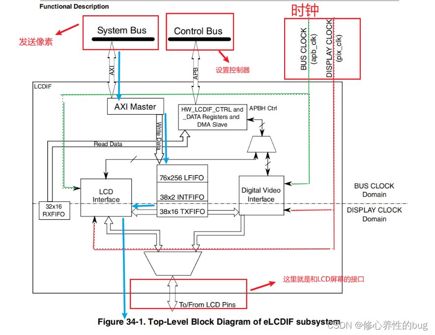
时钟:
elcdf模块包含两个时钟信号,分别是BUS CLOCK(apb_clk)和DISPLAY CLOCK(pix_clk)
分别是图中的绿色线和红色线
![![外链图片转存失败,源站可能有防盗链机制,建议将图片保存下来直接上传(img-1bxzTwHU-1665926095096)(C:\Users\WIN10\AppData\Roaming\Typora\typora-user-images\1665906544733.png)]](https://img-blog.csdnimg.cn/d4c66ddfcb8c4a988abc547c4526838c.png)
和截图这里的pix和axi对应起来
总线:
eLCDIF的液晶接口有两个总线接口
System Bus总线,用于向eLCDIF液晶接口的FIFO中写入数据。 即写入像素
Control Bus用于设置eLCDIF用于读、写控制寄存器以及DMA、数据寄存器等等
控制总线的寄存器可以配置显存地址、输入像素数据的格式、输出的数据信号线宽度、 各个控制信号的有效极性以及控制时序中的VSW、VBP等参数,还能配置使用DMA传输
工作流程:
如图中的蓝色箭头
从System Bus总线把像素写入到FIFO里面,经过一系列转换后通过eLCDIF的通讯引脚发送至外接的液晶面板
从图中可以看出,我们用户把数据写给我们的控制器,再由控制器连接到LCD的引脚,这样就可以把数据写给屏幕,所以我们在写驱动的时候也是要设置我们的LCD控制器
完整代码:
#include <linux/module.h>
#include <linux/kernel.h>
#include <linux/err.h>
#include <linux/errno.h>
#include <linux/string.h>
#include <linux/mm.h>
#include <linux/slab.h>
#include <linux/delay.h>
#include <linux/fb.h>
#include <linux/init.h>
#include <linux/dma-mapping.h>
#include <linux/interrupt.h>
#include <linux/platform_device.h>
#include <linux/clk.h>
#include <linux/cpufreq.h>
#include <linux/io.h>
#include <linux/gpio/consumer.h>
#include <video/display_timing.h>
#include <video/of_display_timing.h>


#include "imx6ull_elcdif.h"

struct fb_info *my_fb_info;
dma_addr_t phy_addr;
static struct imx6ull_elcdif *elcdif;
static u32 pseudo_palette[16];
static struct clk *clk_pix;
static struct clk *clk_axi;

static struct fb_ops lcd_drv_fbops = {
	.owner		= THIS_MODULE,
	.fb_fillrect	= cfb_fillrect,
	.fb_copyarea	= cfb_copyarea,
	.fb_imageblit	= cfb_imageblit,
};


/*
当软件设置这个位时,eLCDIF将开始在SoC和显示器之间传输数据。此位必须保持设置,直到操作完成
*/

static void imx6ull_elcdif_enable(struct imx6ull_elcdif *elcdif)
{
	elcdif->CTRL |= (1<<0);
}

static void imx6ull_elcdif_disable(struct imx6ull_elcdif *elcdif)
{
	elcdif->CTRL &= ~(1<<0);
}

static int imx6ull_elcdif_init(struct imx6ull_elcdif *elcdif, struct fb_info *info, struct display_timing  *dt, unsigned int bus_width)
{
	unsigned int input_data_format;
	unsigned int data_bus_width;
	unsigned int hsync_active = 0;
	unsigned int vsync_active = 0;
	unsigned int de_active = 0;
	unsigned int pixelclk_active = 0;

	/*
     * 初始化LCD控制器的CTRL寄存器
     * [19]       :  1      : DOTCLK和DVI modes需要设置为1
     * [17]       :  1      : 设置为1工作在DOTCLK模式
     * [15:14]    : 00      : 输入数据不交换(小端模式)默认就为0,不需设置
     * [13:12]    : 00      : CSC数据不交换(小端模式)默认就为0,不需设置
     * [11:10]    : 11		: 数据总线为24bit
     * [9:8]    根据显示屏资源文件bpp来设置:8位0x1 , 16位0x0 ,24位0x3
     * [5]        :  1      : 设置elcdif工作在主机模式
     * [1]        :  0      : 24位数据均是有效数据,默认就为0,不需设置
	 */


	/* elcdif正常运行bit31、bit30  必须设置为0  */
	elcdif->CTRL &= ~((1 << 31) | (1 << 30));

	if(info->var.bits_per_pixel == 16)
		input_data_format = 0x0;
	else if (info->var.bits_per_pixel == 8)
		input_data_format = 0x1;
	else if (info->var.bits_per_pixel == 18)
		input_data_format = 0x2;
	else if (info->var.bits_per_pixel == 24)
		input_data_format = 0x3;
	else
	{
		printk(KERN_EMERG"Don't support %d bpp\n", info->var.bits_per_pixel);
		return -1;
	}

	if (bus_width == 16)
		data_bus_width = 0x0;
	else if (bus_width == 8)
		data_bus_width = 0x01;
	else if (bus_width == 18)
		data_bus_width = 0x02;
	else if (bus_width == 24)
		data_bus_width = 0x03;
	else
	{
		printk(KERN_EMERG"Don't support %d bit data bus mode\n", info->var.bits_per_pixel);
		return -1;
	}


	/* 设置RGB格式和数据宽度 */
	elcdif->CTRL &= ~((0x03 << 8) | (0x03 << 10));//清除8,9 ,10,11位
	elcdif->CTRL |= ((input_data_format << 8) | (data_bus_width << 10));//设置为16位表示一个像素,总线为24位

    elcdif->CTRL |= (1 << 17); /* 选择 RGB 模式 VSYNC/HSYNC/DOTCLK/启用接口模式*/
    elcdif->CTRL |= (1 << 19); /* 选择 RGB 模式 开启显示 */
    elcdif->CTRL |= (1 << 5);  /* 设置elcdf接口为主模式 */

	/*
	* 设置ELCDIF的寄存器CTRL1
	* 根据bpp设置,bpp为24或32才设置
	* [19:16]  : 111  :表示ARGB传输格式模式下,传输24位无压缩数据,A通道不用传输)
	*/

	if (info->var.bits_per_pixel == 24 || info->var.bits_per_pixel == 32)
	{
		/* 设置32位有效位的低24位有效 */
		elcdif->CTRL1 &= ~(0xf << 16);
		elcdif->CTRL1 |= (0x7 << 16);
	}
	else
	{
		elcdif->CTRL1 |= (0xf << 16);	//BYTE_PACKING_FORMAT
	}

	/* 设置LCD分辨率 */
	elcdif->TRANSFER_COUNT &= ~0xffffffff;
	elcdif->TRANSFER_COUNT |= (dt->vactive.typ << 16); /* [31:16] 设置LCD垂直分辨率 */
	elcdif->TRANSFER_COUNT |= (dt->hactive.typ << 0); /* [15:0] 设置LCD垂直分辨率 */


	/*
	* 设置ELCDIF的VDCTRL0寄存器
	* [29] 0 : VSYNC输出  ,默认为0,无需设置
	* [28] 1 : 在DOTCLK模式下,设置1硬件会产生使能ENABLE输出
	* [27] 0 : VSYNC低电平有效	,根据屏幕配置文件将其设置为0
	* [26] 0 : HSYNC低电平有效 , 根据屏幕配置文件将其设置为0
	* [25] 1 : DOTCLK下降沿有效 ,根据屏幕配置文件将其设置为1
	* [24] 1 : ENABLE信号高电平有效,根据屏幕配置文件将其设置为1
	* [21] 1 : 帧同步周期单位,DOTCLK mode设置为1
	* [20] 1 : 帧同步脉冲宽度单位,DOTCLK mode设置为1
	* [17:0] :  vysnc脉冲宽度
	*/
    elcdif->VDCTRL0 |= (1 << 28);  /* 生成使能信号 */
    elcdif->VDCTRL0 |= (1 << 21);  /* 设置VSYNC周期 的单位为显示时钟的时钟周期 */
    elcdif->VDCTRL0 |= (1 << 20);  /* 设置VSYNC 脉冲宽度的单位为显示时钟的时钟周期 */

	if (dt->flags & DISPLAY_FLAGS_DE_HIGH)
		de_active = 1;
	if (dt->flags & DISPLAY_FLAGS_PIXDATA_POSEDGE)
		pixelclk_active = 1;
	if (dt->flags & DISPLAY_FLAGS_HSYNC_HIGH)
		hsync_active = 1;
	if (dt->flags & DISPLAY_FLAGS_VSYNC_HIGH)
		vsync_active = 1;

	/* 设置信号极性 */
	elcdif->VDCTRL0 &= ~(0xf << 24);            /* bit24~bit27清零 */
	elcdif->VDCTRL0 |= (de_active << 24);       /* 设置数据使能信号的有效电平 */
	elcdif->VDCTRL0 |= (pixelclk_active << 25); /* 设置时钟信号极性 */
	elcdif->VDCTRL0 |= (hsync_active << 26);    /* 设置HSYNC有效电平 */
	elcdif->VDCTRL0 |= (vsync_active << 27);    /* 设置VSYNC有效电平 */

	elcdif->VDCTRL0 |= (dt->vsync_len.typ << 0);/* 设置vysnc脉冲宽度 */

	/* 设置VSYNC信号周期 */

	/*
	* 设置ELCDIF的VDCTRL1寄存器
	* 设置垂直方向的总周期:上黑框tvb+垂直同步脉冲tvp+垂直有效高度yres+下黑框tvf
	*/
	elcdif->VDCTRL1 = dt->vsync_len.typ + dt->vactive.typ + dt->vfront_porch.typ + dt->vback_porch.typ;

	/*
	* 设置ELCDIF的VDCTRL2寄存器
	* [18:31]  : 水平同步信号脉冲宽度
	* [17: 0]   : 水平方向总周期
	* 设置水平方向的总周期:左黑框thb+水平同步脉冲thp+水平有效高度xres+右黑框thf
	*/

	elcdif->VDCTRL2 |= (dt->hsync_len.typ << 18); /* 设置hysnc脉冲宽度 */
	/*设置HSYNC信号周期 */
	elcdif->VDCTRL2 |= (dt->hfront_porch.typ + dt->hback_porch.typ + dt->hactive.typ + dt->hsync_len.typ);

	/*
	* 设置ELCDIF的VDCTRL3寄存器
	* [27:16] :水平方向上的等待时钟数 =thb + thp
	* [15:0]  : 垂直方向上的等待时钟数 = tvb + tvp
	*/
    elcdif->VDCTRL3 |= ((dt->hback_porch.typ + dt->hsync_len.typ) << 16);
    elcdif->VDCTRL3 |= (dt->vback_porch.typ + dt->vsync_len.typ);

	/*
	* 设置ELCDIF的VDCTRL4寄存器
	* [18]	   使用VSHYNC、HSYNC、DOTCLK模式此为置1
	* [17:0]  : 水平方向的宽度
	*/
	elcdif->VDCTRL4 |= (1 << 18);
	elcdif->VDCTRL4 |= (dt->hactive.typ << 0);

    elcdif->CUR_BUF  = info->fix.smem_start;
    elcdif->NEXT_BUF = info->fix.smem_start;

	return 0;
}


/*匹配成功之后进入该函数函数*/
static int mylcd_probe(struct platform_device *pdev)
{
    struct resource *res;
    struct device_node *display_np;
    struct display_timing  *dt = NULL;
    struct display_timings *timings = NULL;

    unsigned int bits_per_pixel;
    unsigned int bus_width;


    /*从设备树里面获得reg即lcdif的地址*/
	res = platform_get_resource(pdev, IORESOURCE_MEM, 0);
	elcdif = devm_ioremap_resource(&pdev->dev, res);//映射到物理地址,后面就可以来操作寄存器

    /*获得时序*/
	display_np = of_parse_phandle(pdev->dev.of_node, "display", 0);//在节点lcdif里面依据节点名字"display"找到该节点解析
	timings = of_get_display_timings(display_np);//获得display的timimg
	dt = timings->timings[timings->native_mode];

    of_property_read_u32(display_np, "bits-per-pixel", &bits_per_pixel);//找到位深
	if (bits_per_pixel != 16)
	{
		printk(KERN_EMERG"not support %d bpp!\n", bits_per_pixel);
		return -1;
	}

    of_property_read_u32(display_np, "bus-width", &bus_width);//找到总线长度


	clk_pix = devm_clk_get(&pdev->dev, "pix");//获得时钟pix
	clk_axi = devm_clk_get(&pdev->dev, "axi");//获得时钟axi

	clk_set_rate(clk_pix, dt->pixelclock.typ);//设置,”pix”是像素时钟,需要根据具体的LCD屏参数设置,axi是系统就设置好了,不需要设置

	clk_prepare_enable(clk_pix);//使能
	clk_prepare_enable(clk_axi);


    /*1.分配fb_info*/

    my_fb_info = framebuffer_alloc(0,&pdev->dev);

    /*2.设置fb_info参数*/

    /*设置var参数*/

    /*分辨率*/
    my_fb_info->var.xres =  dt->hactive.typ;//设置x
    my_fb_info->var.yres =  dt->vactive.typ;
    /*位深*/
    my_fb_info->var.bits_per_pixel = bits_per_pixel;//设置位深即用多少位来表示一个像素
    /*RGB565*/
    my_fb_info->var.red.offset = 11;
    my_fb_info->var.red.length = 5;

    my_fb_info->var.green.offset = 5;
    my_fb_info->var.green.length = 6;

    my_fb_info->var.blue.offset = 0;
    my_fb_info->var.blue.length = 5;

    /*设置fix*/


    	/* 设置固定参数 */
	// strcpy(my_fb_info->fix.id, "fire,lcd");
    my_fb_info->fix.line_length = my_fb_info->var.xres * my_fb_info->var.bits_per_pixel /8;  //设置一行有多少个字节
    my_fb_info->fix.smem_len = my_fb_info->var.xres * my_fb_info->var.yres * my_fb_info->var.bits_per_pixel /8 ; //显存的长度
    /*这里不能使用vmalloc来分配内存,因为显存要求物理内存必须连续*/
    my_fb_info->screen_base = dma_alloc_wc(NULL,my_fb_info->fix.smem_len,&phy_addr,GFP_KERNEL); //分配显存地址,返回值为虚拟地址
    my_fb_info->fix.smem_start = phy_addr;//显存起始位置  物理地址
    my_fb_info->fix.type = FB_TYPE_PACKED_PIXELS;
    my_fb_info->fix.visual = FB_VISUAL_TRUECOLOR;//真彩色

    /*设置文件操作集*/
    my_fb_info->fbops = &lcd_drv_fbops;
    my_fb_info->pseudo_palette = pseudo_palette;

    /*3.注册到内核*/
    register_framebuffer(my_fb_info);//在fbmem.c里面调用class_create,创建一个类,之后等调用这个函数时才会创建一个设备文件即调用device_create


    /*4.硬件操作*/
    /* elcdif控制器硬件初始化 */
	imx6ull_elcdif_init(elcdif, my_fb_info, dt, bus_width);
	imx6ull_elcdif_enable(elcdif);

    printk(KERN_EMERG"match success!\n");

return 0;
}


/*移除函数*/
static int mylcd_remove(struct platform_device *pdev)
{

    unregister_framebuffer(my_fb_info);
    imx6ull_elcdif_disable(elcdif);
    framebuffer_release(my_fb_info);

	printk(KERN_EMERG"module exit!\n");
    return 0;
}


/*设备树匹配*/
static const struct of_device_id mylcd_of_match[] = {
	{ .compatible = "ljm,lcd_drv", },  //匹配属性名字
	{ },
};


/*完善平台总线结构体*/
static struct platform_driver mylcd_driver = {
	.driver = {
		.name = "ljm,lcd_drv",
		.of_match_table = mylcd_of_match,
	},
	.probe = mylcd_probe,
	.remove = mylcd_remove,
};


/* 1. 入口函数 */
static int __init lcd_drv_init(void)
{
	int ret;

	ret = platform_driver_register(&mylcd_driver);
	if (ret)
		return ret;

	return 0;
}

/* 2. 出口函数 */
static void __exit lcd_drv_exit(void)
{
	platform_driver_unregister(&mylcd_driver); //注销平台总线的时候就会调用mylcd_remove函数
}


module_init(lcd_drv_init);
module_exit(lcd_drv_exit);

MODULE_AUTHOR("LJM");
MODULE_DESCRIPTION("Framebuffer driver for the linux");
MODULE_LICENSE("GPL");
#ifndef __IMX6ULL_ELCDIF_H
#define __IMX6ULL_ELCDIF_H

/** LCDIF - Register Layout Typedef */
struct imx6ull_elcdif{
  volatile unsigned int CTRL;                              /**< eLCDIF General Control Register, offset: 0x0 */
  volatile unsigned int CTRL_SET;                          /**< eLCDIF General Control Register, offset: 0x4 */
  volatile unsigned int CTRL_CLR;                          /**< eLCDIF General Control Register, offset: 0x8 */
  volatile unsigned int CTRL_TOG;                          /**< eLCDIF General Control Register, offset: 0xC */
  volatile unsigned int CTRL1;                             /**< eLCDIF General Control1 Register, offset: 0x10 */
  volatile unsigned int CTRL1_SET;                         /**< eLCDIF General Control1 Register, offset: 0x14 */
  volatile unsigned int CTRL1_CLR;                         /**< eLCDIF General Control1 Register, offset: 0x18 */
  volatile unsigned int CTRL1_TOG;                         /**< eLCDIF General Control1 Register, offset: 0x1C */
  volatile unsigned int CTRL2;                             /**< eLCDIF General Control2 Register, offset: 0x20 */
  volatile unsigned int CTRL2_SET;                         /**< eLCDIF General Control2 Register, offset: 0x24 */
  volatile unsigned int CTRL2_CLR;                         /**< eLCDIF General Control2 Register, offset: 0x28 */
  volatile unsigned int CTRL2_TOG;                         /**< eLCDIF General Control2 Register, offset: 0x2C */
  volatile unsigned int TRANSFER_COUNT;                    /**< eLCDIF Horizontal and Vertical Valid Data Count Register, offset: 0x30 */
       unsigned char RESERVED_0[12];
  volatile unsigned int CUR_BUF;                           /**< LCD Interface Current Buffer Address Register, offset: 0x40 */
       unsigned char RESERVED_1[12];
  volatile unsigned int NEXT_BUF;                          /**< LCD Interface Next Buffer Address Register, offset: 0x50 */
       unsigned char RESERVED_2[12];
  volatile unsigned int TIMING;                            /**< LCD Interface Timing Register, offset: 0x60 */
       unsigned char RESERVED_3[12];
  volatile unsigned int VDCTRL0;                           /**< eLCDIF VSYNC Mode and Dotclk Mode Control Register0, offset: 0x70 */
  volatile unsigned int VDCTRL0_SET;                       /**< eLCDIF VSYNC Mode and Dotclk Mode Control Register0, offset: 0x74 */
  volatile unsigned int VDCTRL0_CLR;                       /**< eLCDIF VSYNC Mode and Dotclk Mode Control Register0, offset: 0x78 */
  volatile unsigned int VDCTRL0_TOG;                       /**< eLCDIF VSYNC Mode and Dotclk Mode Control Register0, offset: 0x7C */
  volatile unsigned int VDCTRL1;                           /**< eLCDIF VSYNC Mode and Dotclk Mode Control Register1, offset: 0x80 */
       unsigned char RESERVED_4[12];
  volatile unsigned int VDCTRL2;                           /**< LCDIF VSYNC Mode and Dotclk Mode Control Register2, offset: 0x90 */
       unsigned char RESERVED_5[12];
  volatile unsigned int VDCTRL3;                           /**< eLCDIF VSYNC Mode and Dotclk Mode Control Register3, offset: 0xA0 */
       unsigned char RESERVED_6[12];
  volatile unsigned int VDCTRL4;                           /**< eLCDIF VSYNC Mode and Dotclk Mode Control Register4, offset: 0xB0 */
       unsigned char RESERVED_7[12];
  volatile unsigned int DVICTRL0;                          /**< Digital Video Interface Control0 Register, offset: 0xC0 */
       unsigned char RESERVED_8[12];
  volatile unsigned int DVICTRL1;                          /**< Digital Video Interface Control1 Register, offset: 0xD0 */
       unsigned char RESERVED_9[12];
  volatile unsigned int DVICTRL2;                          /**< Digital Video Interface Control2 Register, offset: 0xE0 */
       unsigned char RESERVED_10[12];
  volatile unsigned int DVICTRL3;                          /**< Digital Video Interface Control3 Register, offset: 0xF0 */
       unsigned char RESERVED_11[12];
  volatile unsigned int DVICTRL4;                          /**< Digital Video Interface Control4 Register, offset: 0x100 */
       unsigned char RESERVED_12[12];
  volatile unsigned int CSC_COEFF0;                        /**< RGB to YCbCr 4:2:2 CSC Coefficient0 Register, offset: 0x110 */
       unsigned char RESERVED_13[12];
  volatile unsigned int CSC_COEFF1;                        /**< RGB to YCbCr 4:2:2 CSC Coefficient1 Register, offset: 0x120 */
       unsigned char RESERVED_14[12];
  volatile unsigned int CSC_COEFF2;                        /**< RGB to YCbCr 4:2:2 CSC Coefficent2 Register, offset: 0x130 */
       unsigned char RESERVED_15[12];
  volatile unsigned int CSC_COEFF3;                        /**< RGB to YCbCr 4:2:2 CSC Coefficient3 Register, offset: 0x140 */
       unsigned char RESERVED_16[12];
  volatile unsigned int CSC_COEFF4;                        /**< RGB to YCbCr 4:2:2 CSC Coefficient4 Register, offset: 0x150 */
       unsigned char RESERVED_17[12];
  volatile unsigned int CSC_OFFSET;                        /**< RGB to YCbCr 4:2:2 CSC Offset Register, offset: 0x160 */
       unsigned char RESERVED_18[12];
  volatile unsigned int CSC_LIMIT;                         /**< RGB to YCbCr 4:2:2 CSC Limit Register, offset: 0x170 */
       unsigned char RESERVED_19[12];
  volatile unsigned int DATA;                              /**< LCD Interface Data Register, offset: 0x180 */
       unsigned char RESERVED_20[12];
  volatile unsigned int BM_ERROR_STAT;                     /**< Bus Master Error Status Register, offset: 0x190 */
       unsigned char RESERVED_21[12];
  volatile unsigned int CRC_STAT;                          /**< CRC Status Register, offset: 0x1A0 */
       unsigned char RESERVED_22[12];
  volatile const   unsigned int STAT;                              /**< LCD Interface Status Register, offset: 0x1B0 */
       unsigned char RESERVED_23[76];
  volatile unsigned int THRES;                             /**< eLCDIF Threshold Register, offset: 0x200 */
       unsigned char RESERVED_24[12];
  volatile unsigned int AS_CTRL;                           /**< eLCDIF AS Buffer Control Register, offset: 0x210 */
       unsigned char RESERVED_25[12];
  volatile unsigned int AS_BUF;                            /**< Alpha Surface Buffer Pointer, offset: 0x220 */
       unsigned char RESERVED_26[12];
  volatile unsigned int AS_NEXT_BUF;                       /**< , offset: 0x230 */
       unsigned char RESERVED_27[12];
  volatile unsigned int AS_CLRKEYLOW;                      /**< eLCDIF Overlay Color Key Low, offset: 0x240 */
       unsigned char RESERVED_28[12];
  volatile unsigned int AS_CLRKEYHIGH;                     /**< eLCDIF Overlay Color Key High, offset: 0x250 */
       unsigned char RESERVED_29[12];
  volatile unsigned int SYNC_DELAY;                        /**< LCD working insync mode with CSI for VSYNC delay, offset: 0x260 */
} ;


#endif /* __IMX6ULL_ELCDIF_H */


 6438
6438


 被折叠的 条评论
为什么被折叠?
被折叠的 条评论
为什么被折叠?
 到【灌水乐园】发言


