


开发环境
1、e2 studio
2、R5F1115AxFL
概述
1、网上关于I2C从机的资料很少,在这里分享下我在瑞萨单片机上实现I2C从机,根据主机发来的数据,从机返回或者保存数据
2、R5F1115AxFL最多支持3个从设备地址(即可以作为三个从设备)
3、从接收模式:直接将数据保存到RAM中,接收完再处理
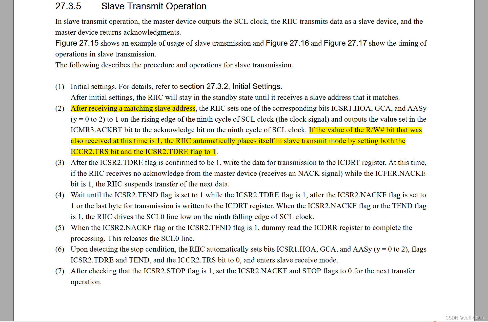
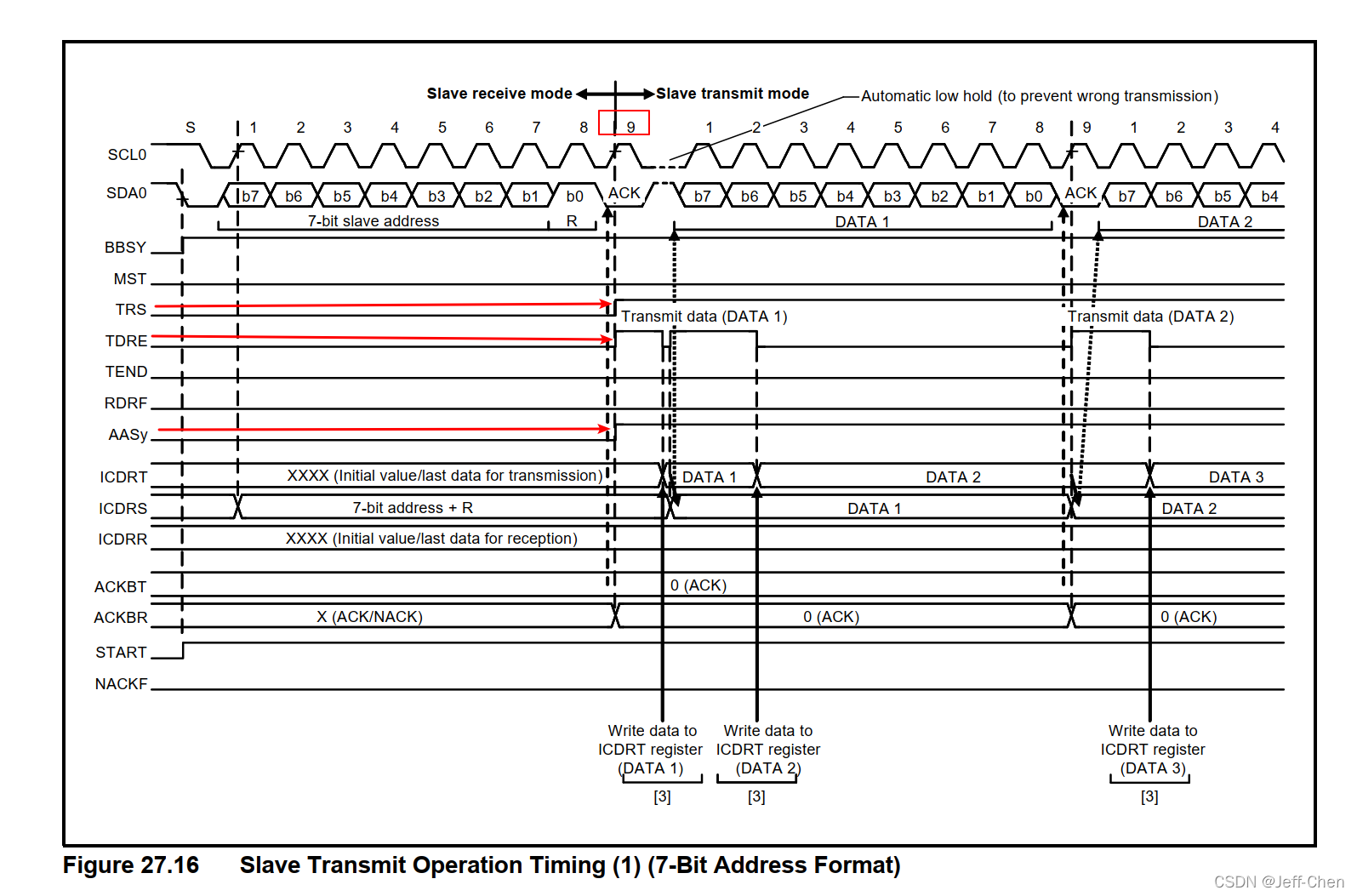
4、从发送模式:按照I2C读取传感器数据经验,主机读取从设备时,从设备需要立刻返回数据的,但是程序要如何实现一收到指令就返回特定的数据?(时钟拉伸)这里先跳过,我们先实现返回固定的数据。
配置
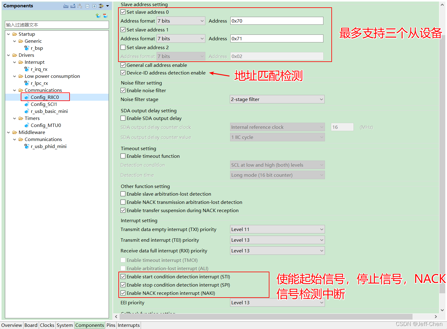
选择I2C从模式,生成代码后,我们把生成的中断处理函数给屏蔽掉,自己另外实现这些中断函数
从接收模式
1、工作流程
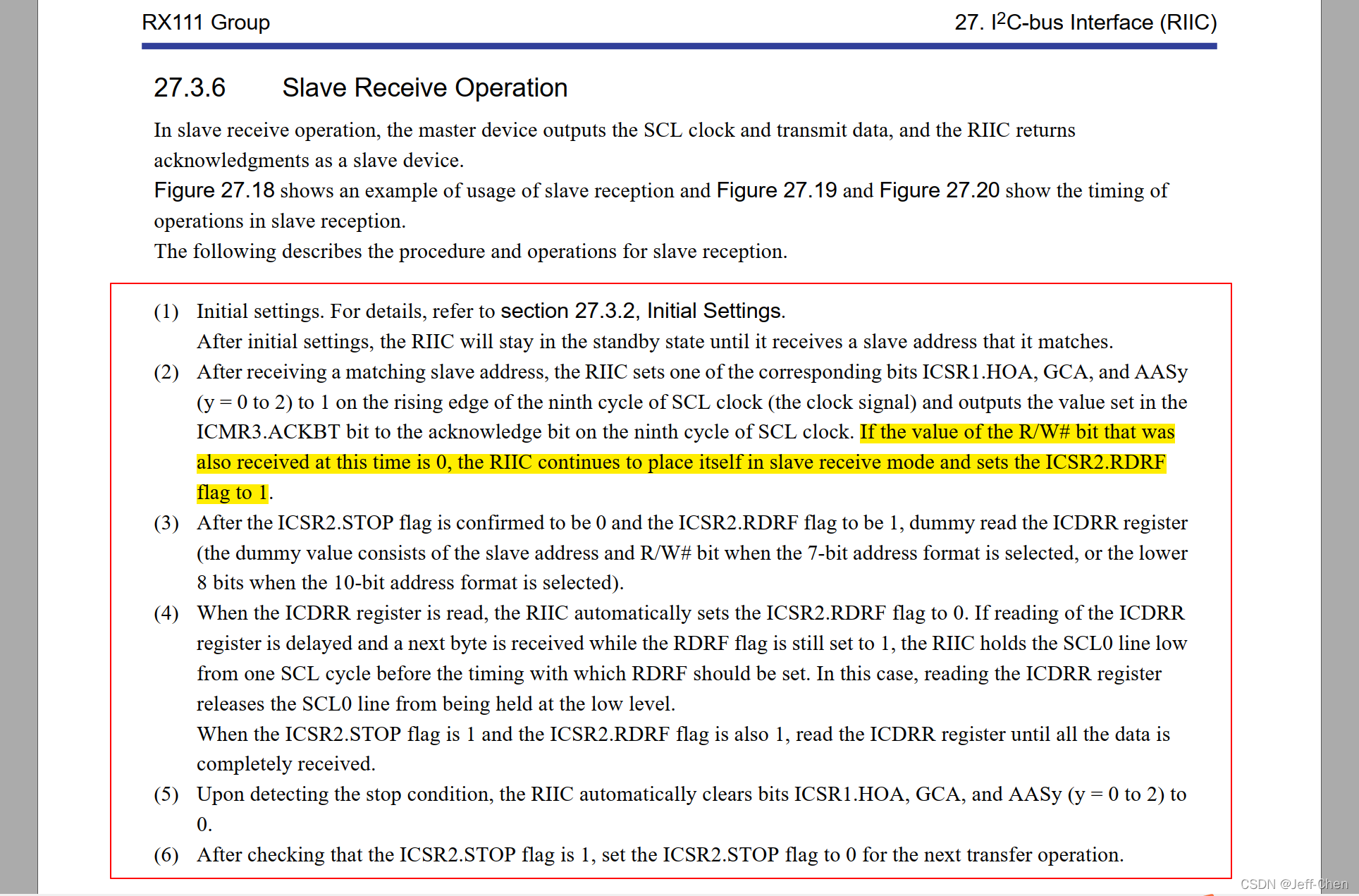
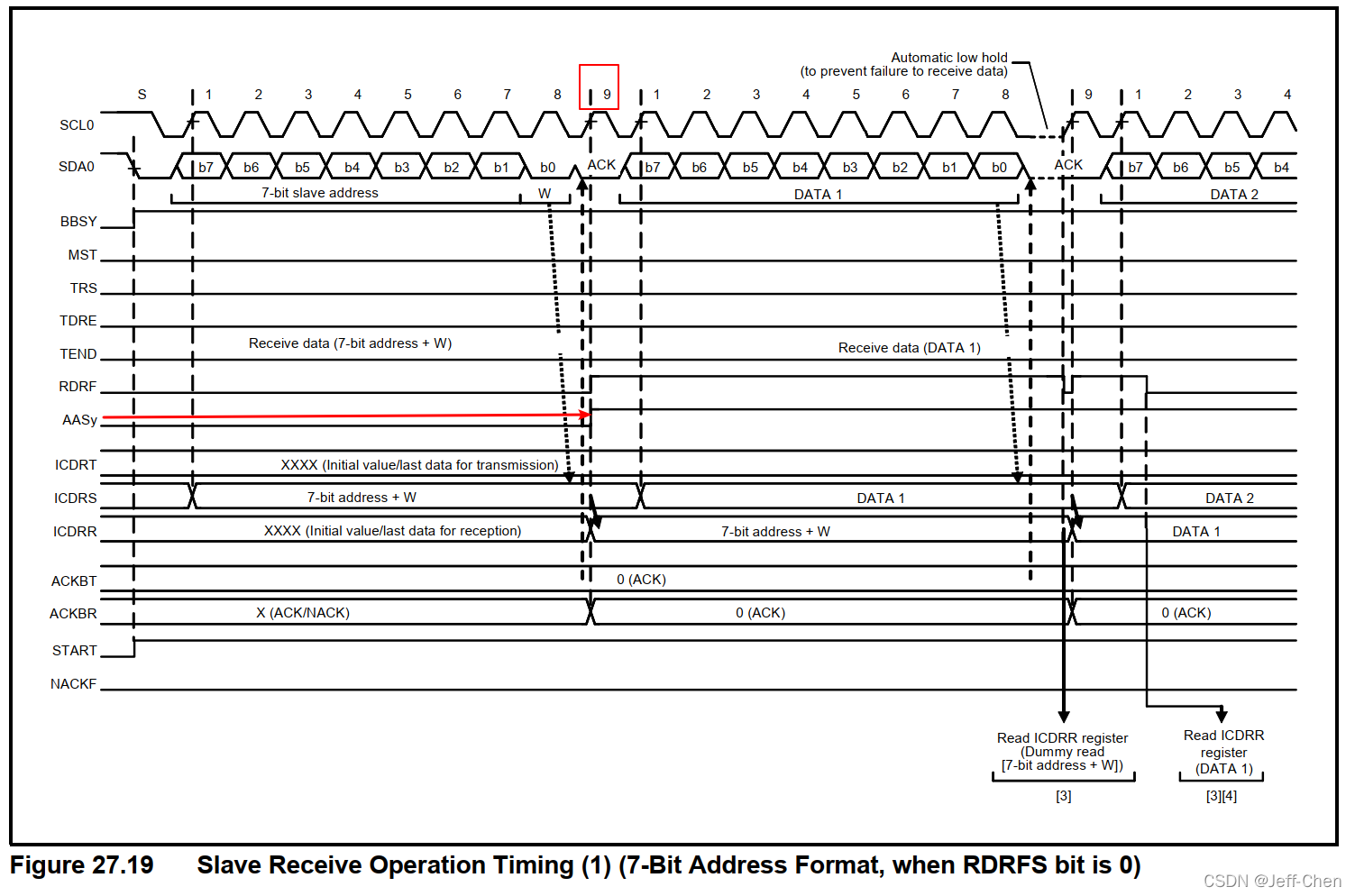
(1)从模式下,I2C会处于待机模式,直到地址检测到匹配
(2)当地址匹配时会在第九个时钟周期的上升沿将ICSR1.HOA, GCA和AASy
(y = 0 to 2)置1。AASy就是对应那个从设备地址匹配,根据这个位我就就可以做多从设备的识别了
(3)后面就不说了,自己看手册
从发送模式
重写I2C相关的中断函数
1、错误中断处理函数。处理起始条件中断、停止条件中断等
static void r_Config_RIIC0_error_interrupt(void)
{
	volatile uint8_t dummy;
	if ((1U == RIIC0.ICIER.BIT.ALIE) && (1U == RIIC0.ICSR2.BIT.AL))
	{

	}
	else if ((1U == RIIC0.ICIER.BIT.TMOIE) && (1U == RIIC0.ICSR2.BIT.TMOF))
	{
		//超时中断处理

	}
	else if ((1U == RIIC0.ICIER.BIT.NAKIE) && (1U == RIIC0.ICSR2.BIT.NACKF))
	{
		//NACK中断处理
		 dummy = RIIC0.ICDRR;
		while (1U != RIIC0.ICSR2.BIT.STOP)
		{
			nop();
		}
		RIIC0.ICSR2.BIT.NACKF = 0U;
		RIIC0.ICSR2.BIT.STOP = 0U;
		i2c_drv[i2c_dev.id].tx_cnt = 0;
	}
	else if (1U == RIIC0.ICSR2.BIT.STOP)	/* detect stop condition       */
    {
        /*After the ICSR2.STOP flag is confirmed to be 0 and the ICSR2.RDRF flag to be 1, dummy read the ICDRR register*/
        if (1 == RIIC0.ICSR2.BIT.RDRF)
            dummy = RIIC0.ICDRR;

        /*After checking that the ICSR2.STOP flag is 1, set the ICSR2.STOP flag to 0 for the next transfer operation*/
        RIIC0.ICSR2.BIT.NACKF = 0U;
        RIIC0.ICSR2.BIT.STOP = 0U;

		/*接收完成*/
        //i2c_drv[i2c_dev.id].rx_len = i2c_drv[i2c_dev.id].rx_cnt;
        //i2c_drv[i2c_dev.id].rx_cnt = 0;
        //i2c_dev.dummy = 0;
    }
    else
    {
    	if (1U == RIIC0.ICSR2.BIT.START)	 /* detect start condition     */
    	{
    		RIIC0.ICSR2.BIT.START = 0;
			//i2c_dev.dummy = 0;
    		while( 0 == RIIC0.ICSR2.BIT.RDRF)//等待第九个时钟中期到
    		{
    			nop();
    		}
			/*判断是哪个从设备和主机通信
			根据标志决定将接收的数据保存到哪个缓冲区,或者将哪个缓存的数据发送出去
			*/
    		if(1 == RIIC0.ICSR1.BIT.GCA || 1 == RIIC0.ICSR1.BIT.AAS0)
    		{
    			//从设备匹配0
    		}
    		else if(1 == RIIC0.ICSR1.BIT.AAS1)
    		{
    			//从设备匹配1
    		}
    		else if(1 == RIIC0.ICSR1.BIT.AAS2)
    		{
    			//从设备匹配2
    		}
    		i2c_dev.model = RIIC0.ICCR2.BIT.TRS;// 从设备处于发送还是接收模式
    	}

    }
}
2、发送中断
static void r_Config_RIIC0_transmit_interrupt(void)
{
	if(I2C_MODEL_TX == RIIC0.ICCR2.BIT.TRS)//发送模式
	{
		if(1 ==RIIC0.ICSR2.BIT.TDRE)//发送中断标志
		{
			//根据匹配地址决定将哪个缓冲区数据发送出去
			//RIIC0.ICDRT = i2c_drv[i2c_dev.id].pTbuf[i2c_drv[i2c_dev.id].tx_cnt];
			//i2c_drv[i2c_dev.id].tx_cnt++;
		}

	}
}

static void r_Config_RIIC0_transmitend_interrupt(void)
{
    volatile uint8_t dummy;

    //if(I2C_MODEL_TX == i2c_dev.model)
    {

        /* Dummy read to release SCL */
        dummy = RIIC0.ICDRR;

    }
}
3、接收中断
static void r_Config_RIIC0_receive_interrupt(void)
{
	uint8_t dummy;
	if(I2C_MODEL_RX == RIIC0.ICCR2.BIT.TRS)
	{
		if (0 == i2c_dev.dummy)
		{
			dummy = RIIC0.ICDRR;//i2c设备地址
			i2c_dev.dummy = 1;
			return;
		}
		RIIC0.ICMR3.BIT.ACKWP = 1U;
		RIIC0.ICMR3.BIT.ACKBT = 0U;
		//保存数据
		//i2c_drv[i2c_dev.id].pRbuf[i2c_drv[i2c_dev.id].rx_cnt] = RIIC0.ICDRR;
		//i2c_drv[i2c_dev.id].rx_cnt++;
	}
	else
	{
		dummy = RIIC0.ICDRR;
	}
}
clock strech时钟拉伸
参考网址https://blog.csdn.net/happygaohualei/article/details/52864694
在发送数据模式下,从设备可能还来不及准备数据,这时候就需要时钟拉伸,等数据准备好后再释放,让主机能继续接收数据(主机支持时钟拉伸功能)


 1238
1238


 被折叠的 条评论
为什么被折叠?
被折叠的 条评论
为什么被折叠?
 到【灌水乐园】发言


