


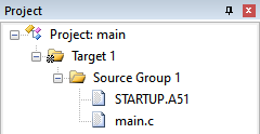
工程结构
原理图

main.c 文件:
/**
 * Interrupt Registers Definition
 */
sfr IE = 0xA8; /* Interrupt Enable Register */

/**
 * Interrupt Registers Bits Definition
 */
/** IE */
#define GLOBAL_IE_EA    (0x80)
#define T0_IE_ET0       (0x02)


/**
 * Timer 0 Registers Definition
 */
sfr TCON    = 0x88; /* Timer 0 & Timer 1 Control Register */
sfr TMOD    = 0x89; /* Timer 0 & Timer 1 Working Mode */
sfr TL0     = 0x8A; /* Timer 0 Counter Low Register */
sfr TH0     = 0x8C; /* Timer 0 Counter High Register */
sfr AUXR    = 0x8E; /* Auxiliary Register */

/**
 * Timer 0 Registers Bits Definition
 */
/** TCON */
#define T0_TCON_TF0     (0x20) /* Timer 0 - Overflow Flag */
#define T0_TCON_TR0     (0x10) /* Timer 0 - Run Control */
/** TMOD */
#define T0_TMOD_GATE    (0x08) /* Timer 0 - Gate Control */
#define T0_TMOD_CT      (0x04) /* Timer 0 - Counter or Timer Selection */
#define T0_TMOD_M1      (0x02) /* Timer 0 - Mode Selection Bit 1 */
#define T0_TMOD_M0      (0x01) /* Timer 0 - Mode Selection Bit 0 */
/** AUXR */
#define T0_AUXR_T0x12   (0x80) /* Timer 0 - Clock Divider Control */


/**
 * Port 1 Registers Definition
 */
sfr P1      = 0x90; /* Port 1 Register */
sfr P1M1    = 0x91; /* Port 1 Configuration Register 1 */
sfr P1M0    = 0x92; /* Port 1 Configuration Register 0 */

/**
 * Port 1 Registers Bits Definition
 */
#define P12M1   (0x04) /* P1.2 - Mode Selection Bit 1 */
#define P12M0   (0x04) /* P1.2 - Mode Selection Bit 0 */


#define enableInterrupts()      IE |= GLOBAL_IE_EA
#define disableInterrupts()     IE &= ~GLOBAL_IE_EA


#define INTERNAL_RC_OSCILLATOR_FREQUENCY_11059200HZ (11059200L) /* 11.0592 MHz */
#define INTERNAL_RC_OSCILLATOR_FREQUENCY_12000000HZ (12000000L) /* 12.0000 MHz */

#define SYSTEM_CLOCK    (INTERNAL_RC_OSCILLATOR_FREQUENCY_12000000HZ)


sbit LED = P1^2; /* LED Control Bit. 0: On, 1: Off */


/**
 * Timer 0 - Mode 0 - 16-Bit Auto Reload
 */
void main() {
    unsigned int period = 2000; // 定时器计数周期,溢出频率 = 1 / 定时器计数周期
    unsigned char divider = 1; // 时钟分频器

    TMOD &= ~(T0_TMOD_M0 | T0_TMOD_M0); // T0 工作模式 0:16 位自动重载模式
    TMOD &= ~T0_TMOD_CT; // T0 作为定时器(对内部系统时钟进行计数)
    TMOD &= ~T0_TMOD_GATE; // T0 的运行只受 TR0 影响,与 INT0 无关
    AUXR |= T0_AUXR_T0x12; // 不分频 T0 的时钟
    divider = ((AUXR & T0_AUXR_T0x12) == T0_AUXR_T0x12) ? 1 : 12;
    TH0 = (65536 - SYSTEM_CLOCK / divider / period) >> 8;
    TL0 = (65536 - SYSTEM_CLOCK / divider / period);


    IE |= T0_IE_ET0; // 允许 T0 在计数溢出之后请求中断
    TCON |= T0_TCON_TR0; // 允许 T0 开始计数

    P1M1 &= ~P12M1;
    P1M0 |=  P12M0;

    enableInterrupts();

    while(1) {}
}

void timer0InterruptService() interrupt 1 {
    LED = !LED;
}
模块化

源文件
新建 stc8h1k08.h 文件,在此声明关于定时器 0 等的特殊功能寄存器:
#ifndef __STC8H1K08_H
#define __STC8H1K08_H


#define INTERNAL_RC_OSCILLATOR_FREQUENCY_05529600HZ (5529600UL)  /*  5.5296 MHz */
#define INTERNAL_RC_OSCILLATOR_FREQUENCY_06000000HZ (6000000UL)  /*  6.0000 MHz */
#define INTERNAL_RC_OSCILLATOR_FREQUENCY_11059200HZ (11059200UL) /* 11.0592 MHz */
#define INTERNAL_RC_OSCILLATOR_FREQUENCY_12000000HZ (12000000UL) /* 12.0000 MHz */
#define INTERNAL_RC_OSCILLATOR_FREQUENCY_18432000HZ (18432000UL) /* 18.4320 MHz */
#define INTERNAL_RC_OSCILLATOR_FREQUENCY_20000000HZ (20000000UL) /* 20.0000 MHz */
#define INTERNAL_RC_OSCILLATOR_FREQUENCY_22118400HZ (22118400UL) /* 22.1184 MHz */
#define INTERNAL_RC_OSCILLATOR_FREQUENCY_24000000HZ (24000000UL) /* 24.0000 MHz */
#define INTERNAL_RC_OSCILLATOR_FREQUENCY_27000000HZ (27000000UL) /* 27.0000 MHz */
#define INTERNAL_RC_OSCILLATOR_FREQUENCY_30000000HZ (30000000UL) /* 30.0000 MHz */
#define INTERNAL_RC_OSCILLATOR_FREQUENCY_33177600HZ (33177600UL) /* 33.1776 MHz */
#define INTERNAL_RC_OSCILLATOR_FREQUENCY_35000000HZ (35000000UL) /* 35.0000 MHz */


/**
 * Interrupt Register Definition
 */
sfr IE = 0xA8; /* Interrupt Enable Register */

/**
 * Interrupt Register Bits Definition
 */
/** IE */
#define IE_EA           (0x80)
#define T0_IE_ET0       (0x02)


/**
 * Timer 0 Registers Definition
 */
sfr TCON    = 0x88; /* Timer 0 & Timer 1 Control Register */
sfr TMOD    = 0x89; /* Timer 0 & Timer 1 Working Mode */
sfr TL0     = 0x8A; /* Timer 0 Counter Low Register */
sfr TH0     = 0x8C; /* Timer 0 Counter High Register */

/**
 * Timer 0 Registers Bits Definition
 */
/** TCON */
#define T0_TCON_TF0     (0x20) /* Timer 0 - Overflow Flag. 1: Timer or counter overflow. */
#define T0_TCON_TR0     (0x10) /* Timer 0 - Run Control. 0: Stop. 1: Run. */
/** TMOD */
#define T0_TMOD_GATE    (0x08) /* Timer 0 - Gate Control */
#define T0_TMOD_CT      (0x04) /* Timer 0 - Counter or Timer Selection. 0: Acts as timer. 1: Acts as counter. */
#define T0_TMOD_M1      (0x02) /* Timer 0 - Mode Selection Bit 1 */
#define T0_TMOD_M0      (0x01) /* Timer 0 - Mode Selection Bit 0 */


/**
 * Auxiliary Register Definition
 */
sfr AUXR                = 0x8E; /* Auxiliary Register */

/**
 * Auxiliary Register Bits Definition
 */
/** AUXR */
#define T0_AUXR_T0x12   (0x80) /* Timer 0 - Clock Divider. 0: Divided by 12. 1: Divided by 1. */


typedef signed char     int8_t;
typedef signed short    int16_t;
typedef signed long     int32_t;


typedef unsigned char   uint8_t;
typedef unsigned short  uint16_t;
typedef unsigned long   uint32_t;


typedef enum {
    false = 0,
    true = !false
} boolean;


#define setRegisterBit(r, b)    r |= b
#define clearRegisterBit(r, b)  r &= ~b


#define enableInterrupts()      setRegisterBit(IE, IE_EA)
#define disableInterrupts()     clearRegisterBit(IE, IE_EA)


#endif
新建 timer0.h 文件,使用宏定义封装对定时器 0 的特殊功能寄存器的操作。当然,也可以使用方法封装。不过,对于调用频率不高的操作,我喜欢用宏定义封装:
#ifndef __STC8H1K08_TIMER_0_H
#define __STC8H1K08_TIMER_0_H


#include "stc8h1k08.h"


typedef enum {
    TIMER0_CLOCK_DIVIDER_1   = 0,
    TIMER0_CLOCK_DIVIDER_12  = 12
} Timer0ClockDivider;

typedef enum {
    TIMER0_MODE_0   = ((unsigned char)0x00), /* 16 位自动重载 */
    TIMER0_MODE_1   = ((unsigned char)0x01), /* 16 位不自动重载 */
    TIMER0_MODE_2   = ((unsigned char)0x02), /* 8 位自动重载 */
    TIMER0_MODE_3   = ((unsigned char)0x03) /* 不可屏蔽中断的 16 位自动重载 */
} Timer0Mode;


#define timer0SetMode(mode) {                           \
    clearRegisterBit(TMOD, (T0_TMOD_M1 | T0_TMOD_M0));  \
    setRegisterBit(TMOD, mode);                         \
}

#define timer0AsTimer() {               \
    clearRegisterBit(TMOD, T0_TMOD_CT); \
}

#define timer0AsCounter() {             \
    setRegisterBit(TMOD, T0_TMOD_CT);   \
}

#define timer0SetTimer(timer) {         \
    uint16_t t = timer;                 \
    TH0 = t >> 8;                       \
    TL0 = t;                            \
}

#define timer0SetCounter(counter) {     \
    timer0SetTimer(counter);            \
}

#define timer0SetClockDivider(divider) {        \
    if(divider == TIMER0_CLOCK_DIVIDER_1) {     \
        setRegisterBit(AUXR, T0_AUXR_T0x12);    \
    } else {                                    \
        clearRegisterBit(AUXR, T0_AUXR_T0x12);  \
    }                                           \
}

#define timer0GetClockDivider() (((AUXR & T0_AUXR_T0x12) == T0_AUXR_T0x12) ? 1 : 12)

#define timer0Run(enable) {                     \
    if(enable == false) {                       \
        clearRegisterBit(TCON, T0_TCON_TR0);    \
    } else {                                    \
        setRegisterBit(TCON, T0_TCON_TR0);      \
    }                                           \
}

#define timer0EnableInterrupt(enable) {         \
    if(enable == false) {                       \
        clearRegisterBit(IE, T0_IE_ET0);        \
    } else {                                    \
        setRegisterBit(IE, T0_IE_ET0);          \
    }                                           \
}


#endif
timer0.c 文件中只有一条语句,可以创建,也可以不创建:
#include "timer0.h"
新建 config.h 配置文件:
#ifndef __CONFIG_H
#define __CONFIG_H


#include "stc8h1k08.h"

#include "timer0.h"


#define SYSTEM_CLOCK    (INTERNAL_RC_OSCILLATOR_FREQUENCY_11059200HZ)


#endif
修改 main.c 文件,其内容如下:
#include "config.h"


/**
 * Port 1 Registers Definition
 */
sfr P1      = 0x90; /* Port 1 Register */
sfr P1M1    = 0x91; /* Port 1 Configuration Register 1 */
sfr P1M0    = 0x92; /* Port 1 Configuration Register 0 */

/**
 * Port 1 Registers Bits Definition
 */
/** P1M1 */
#define P12M1   (0x04) /* P1.2 - Mode Selection Bit 1 */
/** P1M0 */
#define P12M0   (0x04) /* P1.2 - Mode Selection Bit 0 */


sbit LED = P1^2; /* LED Control Bit. 0: On, 1: Off */


/**
 * Timer 0 - Mode 0 - 16-Bit Auto Reload
 */
void main() {
    /**
     * Timer 0 Initialization
     */
    unsigned int frequency = 1000; // 定时器计数溢出频率

    timer0AsTimer();
    timer0SetMode(TIMER0_MODE_0);
    timer0SetClockDivider(TIMER0_CLOCK_DIVIDER_12);
    timer0SetTimer(65536 - SYSTEM_CLOCK / timer0GetClockDivider() / frequency);
    timer0EnableInterrupt(true);
    timer0Run(true);

    /**
     * GPIO Initialization
     */
    P1M1 &= ~P12M1;
    P1M0 |=  P12M0;

    /** */
    enableInterrupts();

    while(1) {}
}

void timer0InterruptService() interrupt 1 {
    LED = !LED;
}
下载
编译,然后使用 STC-ISP 将 hex 文件下载到单片机中,下载选项如下:

测试
下载完成之后,使用示波器测量 P1.2 的输出信号:


 948
948


 被折叠的 条评论
为什么被折叠?
被折叠的 条评论
为什么被折叠?
 到【灌水乐园】发言


